Differentiator VC Feedback Project
Category: Unknown · Tags: — · Posts: 57
#1 — reverselandfill · 2019-04-17
So, I want to make a Differentiator pcb with additional voltage controlled feedback.
I normally feedback it with a summing mixer, but I think CV control will make it even more interesting.
The effect of the feedback is that the edges repeat themselves several times until chaos ensues.
I paired the Cadet Multiplier schematic with the Differentiator and changed some stuff
The design is not finished yet and must be tested.
Right now I’m thinking 1 pcb for pots and jacks, 1 pcb for the main circuit and a panel pcb.
All sandwiched together to decrease depth. 8HP if it fits
- feedback path switch (normal / inverted) - be to tested
- 4 edge filter inputs (instead of 6) - to save space. If it fits, this can be changed to 5 or 6.
- switches for feedback routing
- not added yet, but interesting: diode clipping distortion or more filtering in the feedback path?
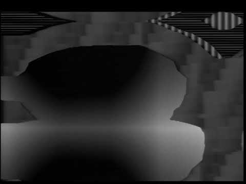
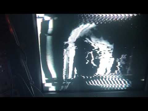
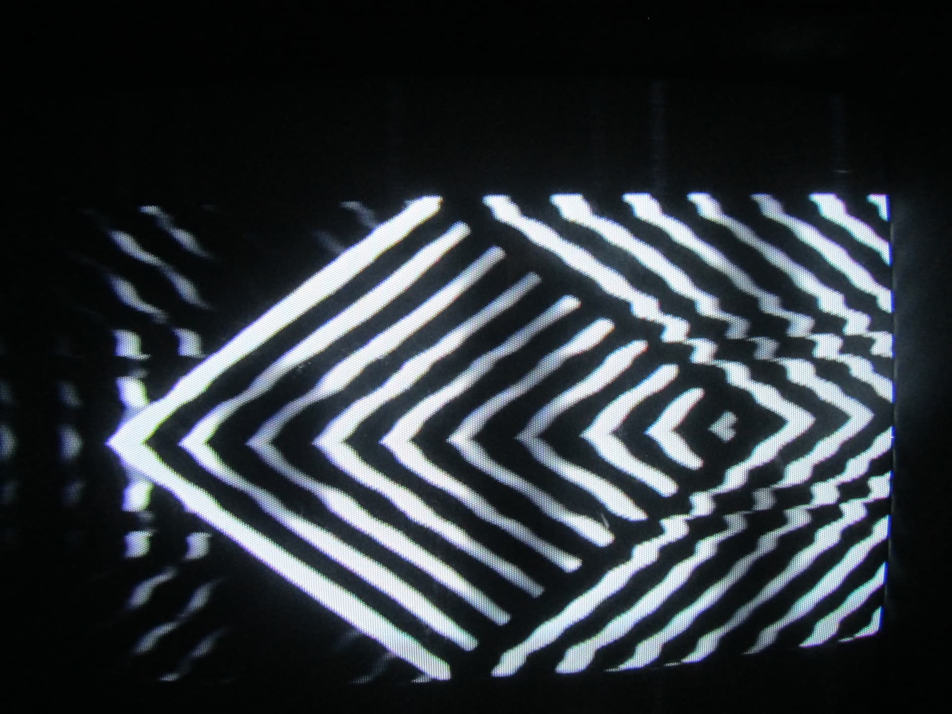
example of feedback edges: (in a patch, no cv yet)
The white dots = edge of the green shape routed though a Differentiator and feedbacked with a modified summing mixer.
(red & blue channel = camera feedback)
Remark: this project is directed towards DIYers and will be open source.
—>> All input and help is welcome!
#2 — reverselandfill · 2019-04-17
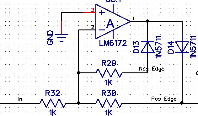
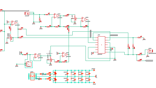
Current schematic:

This will be my first time to do a pcb project with sandwiched pcb’s.
note: I left the 4 quadrant switch in. this has cool effects
#3 — reverselandfill · 2019-04-17
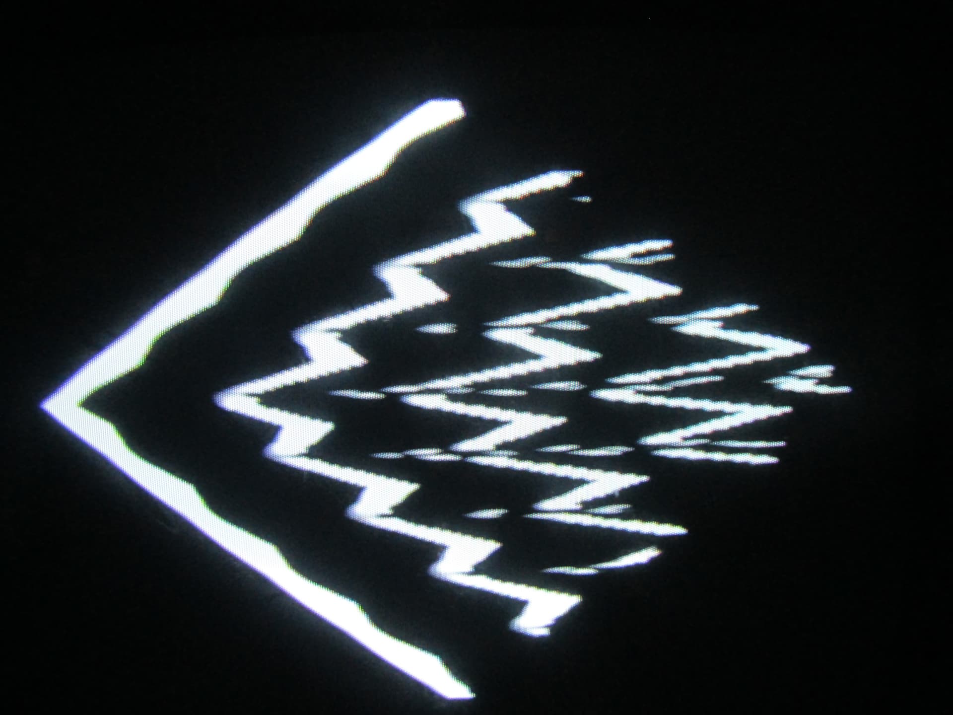
testing with separate modules. fast screensots
The dots appear when the CV is modulated with a VCO.
The signal needs some boosting to get the repeats, so I have to add this in the schematic (or change some values / make a gain control
The feedback path routing adds nice features, so must be implemented on the front panel; with a rotary encoder or multiple positions switch (4x1)
When several inputs are used, the image get more interesting details (picture 2)


#4 — reverselandfill · 2019-04-17
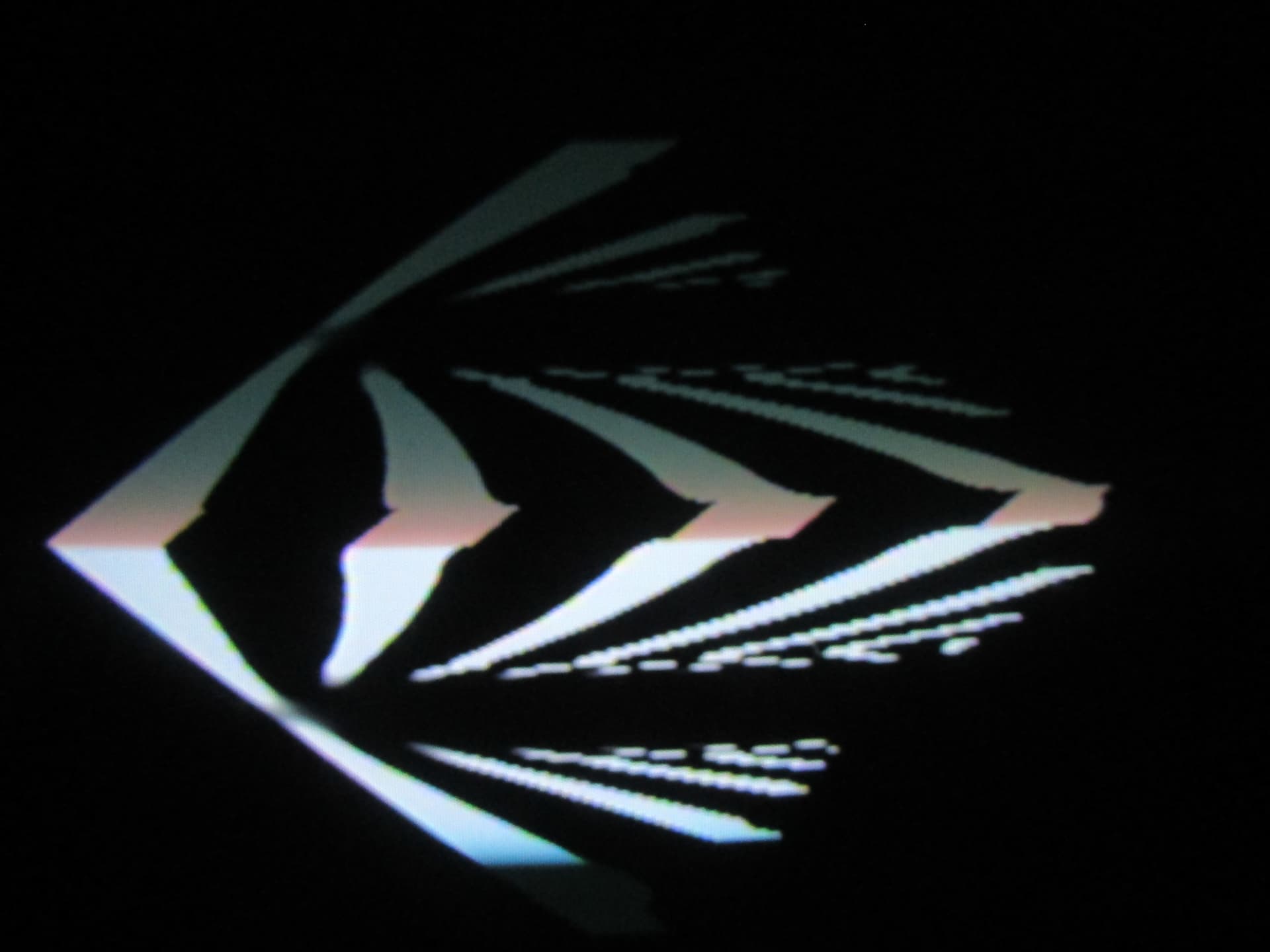
Complex CV possibilities.
pic1: minimal setting
pic2: half way
full on: chaos (not shown)


#5 — reverselandfill · 2019-04-17
a 100k pot (VR3) in the amp stage of the differentiator works pretty good.
it needs a range limiter (r38) for the low end, which value I have to determine yet.
The Chaos tipping point is tricky. but will be solvable with the right resistors.
I’m getting a lot of cool images already

I wonder if r41 & r42 (or r6) can be skipped. they were final outputs, but not anymore
the same with r44, r47, r45, r46.
and is r3 still necessary?


#6 — wednesdayayay · 2019-04-17
the differentiator is one of my favorites I think of it like a little utility mixer basically
a similar idea to the nearness module but for video
this module seems like a neat furthering of that concept. I’m always up for more feedback I’ll happily be following along but have no technical knowledge to lend
#7 — Genlok · 2019-04-17
This is magnificent. I can’t wait to see how this ends up. Sign me up for one when it’s ready!
#8 — aaronsbrown · 2019-04-18
Following with intense interest!
#9 — creatorlars · 2019-04-18
Looks great! As far as skipping some parts, I would leave those resistors there to provide some isaolation from the contacts of the mechanical switches. (Are you using a rotary switch here?)
#10 — reverselandfill · 2019-04-18
The one in the middle is a toggleswitch,
The 4x1 will be either a rotary or a 4position slide switch.
What about r3?
#11 — sean · 2019-04-18
Only sort of half understanding what all is going on here, admittedly, but I wonder if there is a way to introduce variable time/delay to the feedback path for thicker & thinner edge feedback effects (if edge feedback is indeed what is happening here)?
#12 — creatorlars · 2019-04-18
@reverselandfill R3 keeps the input of U3A from floating while the switch is momentarily in a no contact state (which will prevent ringing or other problems you want to avoid.)
#13 — reverselandfill · 2019-04-18
that makes sense, I had not thought about it that way.
Do you see any other points that can use improvement?
#14 — creatorlars · 2019-04-18
R7 and R8 should be ferrite beads and not resistors.
It would be ideal if the switches were replaced by analog multiplexer (74hc4053, etc) but then you need to add a +5V power supply and some input protection to the lines. For a DIY design I would not worry about it. For a production design, it’d be worth the fix.
What is the intention of the SW and SW2 pads and the switch S1? My suggestion would be to turn the LT1251 into a 4 quadrant multiplier – basically crossfade between the inverted and non-inverted signals. U3A and U4B could be eliminated, as you would send the differentiator buffer amp (U4A) to the non-inverting input on one half of the LT1251 and to the inverting input on the other half of LT1251 in parallel.
#15 — creatorlars · 2019-04-18
If you are looking for more ideas for functions, one would be to use a rectifier to split the positive and negative sides of the differentiator output and make them selectable (left edge only, right edge only, etc.)
#16 — reverselandfill · 2019-04-18
r7 & r8 are already ferrites, I don’t have footprints for ferrites
(normally I rename them F1 & f2, not done that yet.)
#17 — reverselandfill · 2019-04-19
sw1 & sw2 : switch pads for the 2quadrant / 4 quadrant mode
S1: switch between positive and negative edges feedback routing
SV2: 4x1 position switch location / rotary
all these will be changed into vertical switches when I decide what to do exactly
note: the 2 & 4 quadrant feedback routing has very different results. maybe it would be interesting to have a gate controlling this. with a 4066 / 4053 or 74HC equivalent. maybe
for feedback options, it is important that the loop gain can be controlled by a CV signal, as it is wired up now.
The test setup gives very good results, so I want to go in that direction.
I’m going to test outputs with rectifiers!
#18 — reverselandfill · 2019-04-20
small schematic update:
pos & neg outputs, for use with the S1/S2 DPDT on/off/on switch, so you cound bypass the feedback path and use the Differentiator “normally”.

#19 — creatorlars · 2019-04-21
2 quadrant in this case is going to be the same as modulating only the top half in 4 quadrant mode: In 2 quadrant mode, you go 0 to 100%. In 4 quadrant mode, you go -100% to +100%. Of course, it is up to you, if you like having the switch. Just saying you don’t lose any features if you remove that switch and just use the 4 quadrant setting (since the inputs are hard tied in this case.) Finding a zero position is more difficult in this case but I think your bypass switch is the superior solution for that issue.
As far as gain goes, you could also add some gain to the LT1251 if you wanted!
For the rectifier circuit, borrow it from the dual clippers in Cadet 2! Like so:
(note you would want to buffer these nets before sending them to the output jack)
#20 — reverselandfill · 2019-04-23
ok, I’m going to try this.
I’ll keep you posted

#21 — reverselandfill · 2019-05-15
I’m still not sure which route I will take.
The x-fade option sounds good, but I hope it will give nice / te same kind of interesting results I had with the things I tried (see above). cq, the amount of feedback
Maybe it will need a polarising pot, to set the zero point of modulation.
#22 — tylerm · 2019-06-26
It’s so fun to watch this progress! Can’t wait to get my hands on one!
#23 — reverselandfill · 2019-06-26
I am a bit swamped with other work right now, I will get working on this next month
#24 — reverselandfill · 2019-12-19
Ok I’m ready to start this funky project up again.
my 1st idea is to make an outline on what functions it should have.
I’ll post some panel options later
Also, if anyone wants to help me with this project (which is a little bit more complex than the Matrix Mixer)
that would be awesome!
#25 — Jefro · 2019-12-19
I’d be super interested in helping to test. I’m a very experienced DIYer and have ~15 years experience testing software (and obviously the DIY projects i’ve put together).
#26 — reverselandfill · 2019-12-19
Thanks Jefro!
First order of business is to design the project.
When the prototype is ready, it would be good to test different system routings.
I’d like to make this module because I like to have this effect without having to patch this all the time.
It is a pretty extensive patch, so it would be useful to have a pre-routed module for this (with some added features)
As before, this is an open source project mainly focused on DIY.
My current idea is to have a module that does voltage controlled feedbacked edge re-iterations (see above patch examples)
The possible options are:
- switchable edge size (voltage control or by manual switch / patchbay)
- triple functions (like my other designs) - mighty be feasible if the panel gets wider
- 4 quadrant modulation depth vs switchable mode from 2 to 4.
- knob functions : Bias (?), cv attenueverter, feedback amount – more?
- and functions more to add
The original LZX Differentiator had 6 inputs (edge thickness/slopes) and 2 outputs (left and right edges)
My 1st design idea had a rotary for 4 inputs (really just 1, but selectable edge thickness) and 2 output (maybe 4 for additional feedback routings
@creatorlars hinted at a variable positive and negative edge outputs (or by CV) . Which sounds like a good plan! The feedback path could be switchable by cv . I have to try if the rate of a CD4066 is fast enough.
#27 — allthesixes666 · 2019-12-30
Hello,
This sounds really great!
I’ve been playing with the IP Differentiator I got from here a while ago
I’d be happy to help with testing, your ideas for additional functionality look really interesting - building/DIY isn’t a problem (currently ordering bits for the triple Function Gen boards & panel I bought off you).
Cheers!
#28 — reverselandfill · 2020-05-14
I want to return to this project.
The functions @creatorlars proposed sound cool. I’m going tosee it I can implement these .
If somebody wants to help me with the schematics, I’d be honored.
I’ll post the updated schematics later
#29 — rempesm · 2020-09-09
@reverselandfill and I have been talking through a few ideas about this design and it’d be great to hear community thoughts on where we could take it.
I’ve been using the Seismic Industries VC Route which uses a DG409 for multiplexing for a 1:4/4:1 windowed keying effect like in this demo:
https://www.youtube.com/watch?v=TfJLvM5QR1kPairing the VC Route up with 4 Differentiator inputs allows you to voltage control the selected feedback path. If you patch a system up like this:
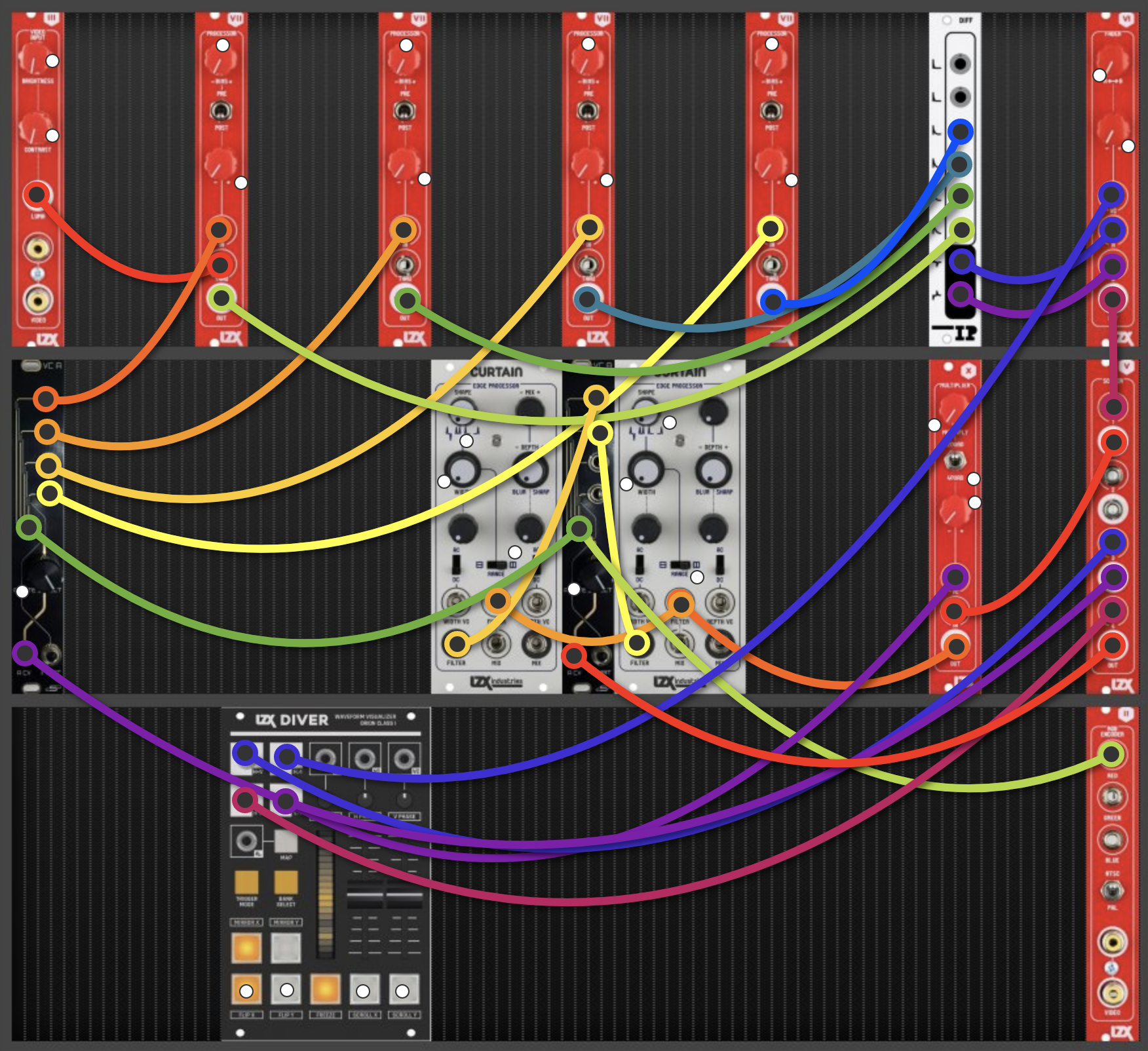
You can get effects like:
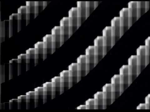
https://www.youtube.com/watch?v=FyH5CUbxBP4or:
https://www.youtube.com/watch?v=hGH7jPron4kI’ve mulled over some variations on this patch and breadboarded up a good chunk of this circuit to test it out. Something along the lines of the Expedition design layout seemed to fit with the overall feature set this module could have so I did a quick rip off sketch of Navigator:
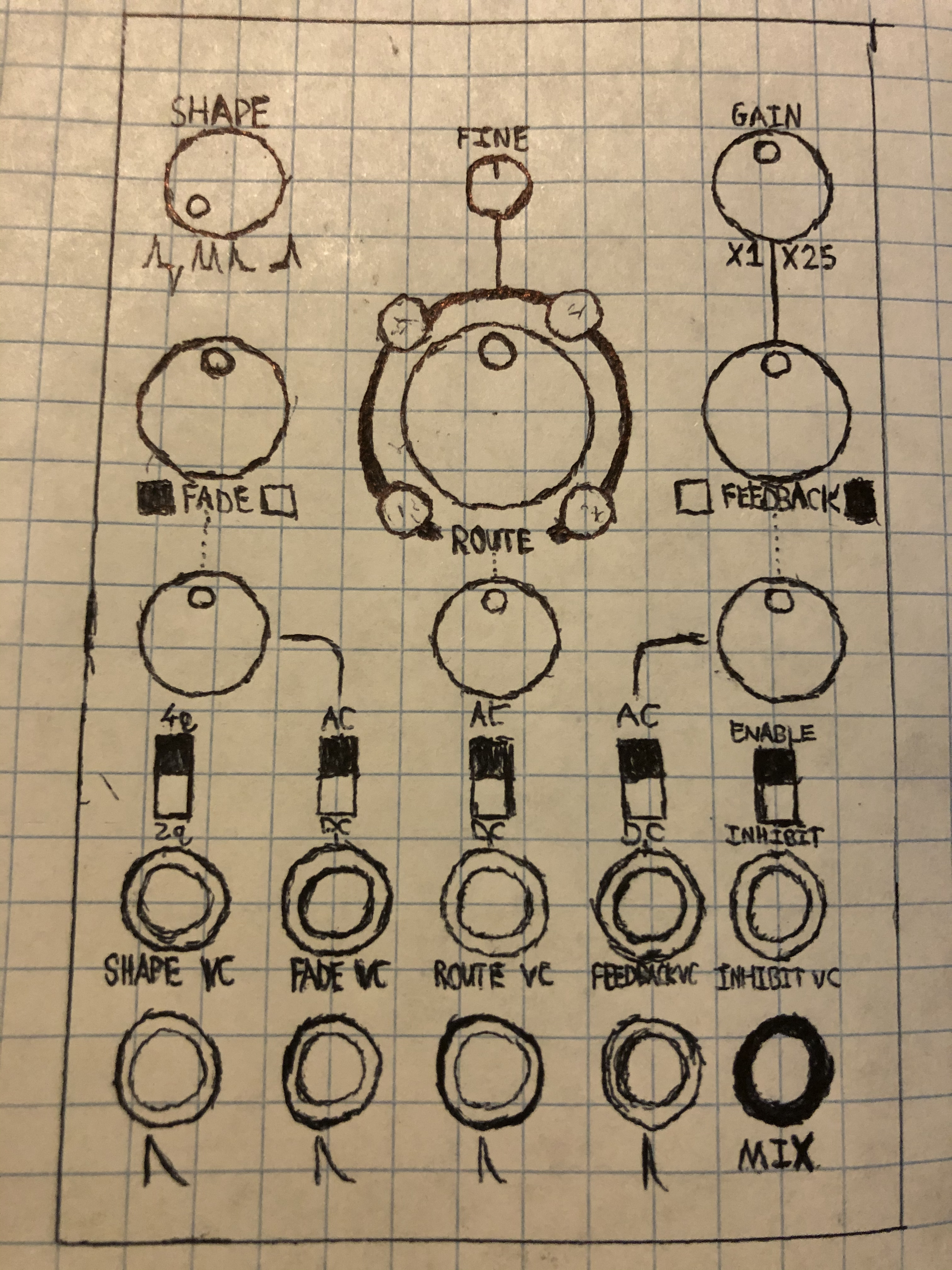
The module can still work as a standard Differentiator with 4 inputs and a manual fade over non-inverted and inverted outputs instead of the original. Just flip right toggle to Inhibit.
The Route control (w/ Fine adjust) selects which of the Differentiator inputs are tied to the Feedback output control. The Route pot is an offset which adds to the Route VC input. This tracks low detail external Luma video pretty well when I replaced the TL074 CV input buffer + offset mixer with LM6172s.
The Gain control (been using 5x gain so far with a 1->5V Scaler) feeds into the Feedback control which is a 4 quadrant multiplier switchable to 2q/VCA. This is fed into the Route control’s internal input. The 4 outputs of the Route circuitry are mixed unity gain into the Differentiator’s 4 inputs.
The Fade control is a Cadet Fader that takes the non-inverted and inverted outputs of the Differentiator and feeds the output into the Shape control.
The Shape pot is the same idea as the one in Curtain (different offset/mixes of the Cadet II clipper circuit, I think) but you can scan through the rectifications with a second voltage controlled router, Shape VC. Shape pot adds an offset to the Shape VC input.
The Enable / Inhibit toggle is a bypass for the feedback path that’s just disabling the DG409’s I/O. The Inhibit VC input can be modulated up to very high audio rate and creates some of the horizontal smears in the clips.
I’m currently working on getting the rest of the circuits up on the breadboard to confirm functionality but would be interested in any feedback!
#30 — allthesixes666 · 2020-09-15
wow! this looks really good - I love the way the feedback looks
I have been making similar effects with some Castle+Cadet+one Differentiator+Matrix Mixer (don’t ask me for the patch tho… it’s all changed since)Anyway, count me IN - hopefully there could be a DIY version… at some point
#31 — rempesm · 2020-09-16
Thanks, I’ve been using variations on this patch a lot recently and video rate filter bank feedback gets my vote! I’m not quite onto the board layout stage yet but it’s likely this will require a SMT design (0805/SOIC ideally) so it’s not ridiculously deep at 16HP.
I’d like to offer bare PCBs at the least but plenty of work to do before we get there!
#32 — Robbertunist · 2020-09-23
This looks really really amazing! Keep up the research @rempesm & @reverselandfill

I’m glad to see that you both got back to this idea 
#33 — reverselandfill · 2021-06-10
I started working on this project again. I just want to make a simple version first, then we will see if it can be a larger module too.
Current featureset:
3 filter inputs, 2 of which can be the the feedback path (with a switch)
CV over feedback amount
Level pot, Feedback pot, Filter gain pot, CV amount pot
pos/neg signal switch
Note: this is a prototype, so some of the controls are experiments
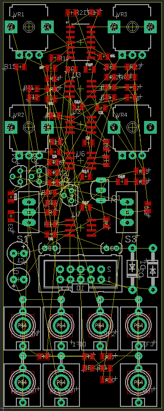
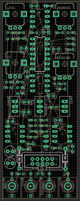
here is my current layout, my first SMT . I have to find certain parts in that format, so that is why the transistors are still TH. I think I will keep the power parts TH (on the backside), the rest of the SMT is on top. The size format is 0805.
#34 — phosphenes · 2021-06-10
Just caught up on the thread now - looks great! I have two differentiators in my system and have always thought it would be nice to have some internal control on the feedback to simplify patching, good to know others are on a similar wavelength.
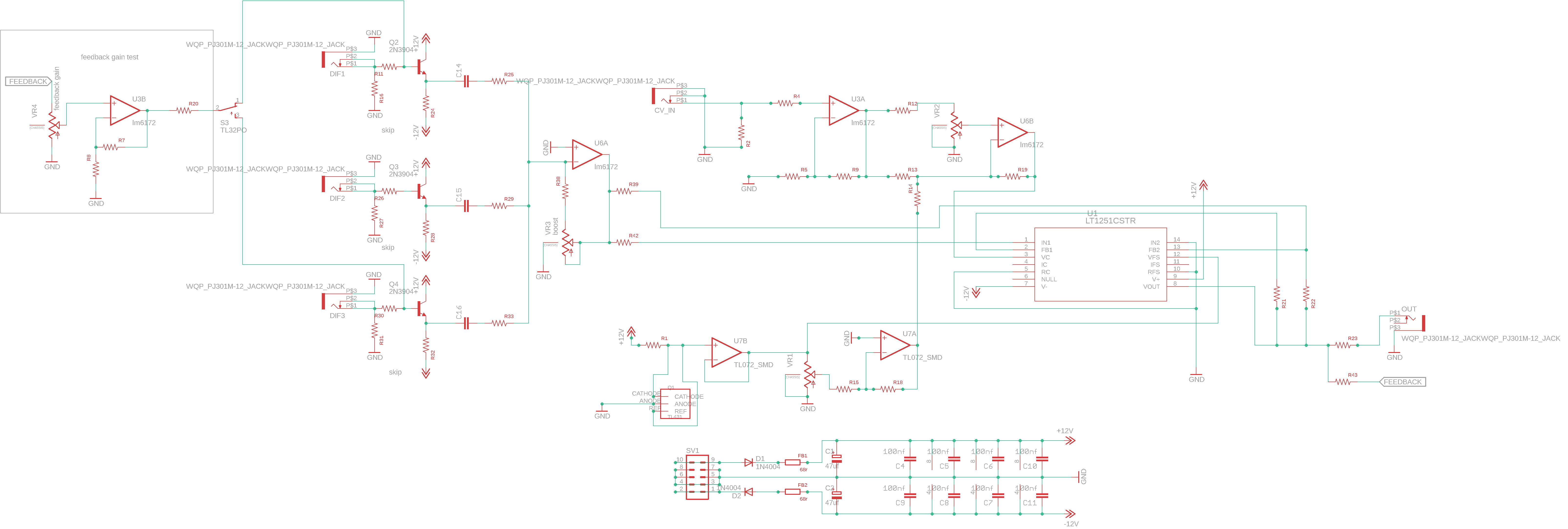
#35 — reverselandfill · 2021-06-10
I’m trying to implement @creatorlars idea from above, which was to lose one LM6172 and crossfade between the negative and positive outputs of the filter.
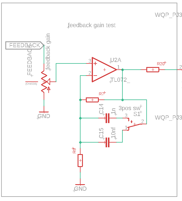
So this is what I got now. Maybe somebody can check if I made errors somewhere?
the feedback gain area is a test. I have to add all resistor & capacitor values since I converted the parts to SMT.
#36 — meudiademorte · 2021-06-10
Really payched when this Project is released!
#37 — reverselandfill · 2021-06-11
creatorlars wrote:
send the differentiator buffer amp (U4A) to the non-inverting input on one half of the LT1251 and to the inverting input on the other half of LT1251 in parallel.
now that I look at it again, my schematic looks wrong. I misread the suggestion a bit

Let’s see if I can setup the lt1251 as described. I’m wondering how to make sure the inverting amp stage is connected correctly to the output pin with resistors…does this look correct?
#38 — Robbertunist · 2021-06-11
meudiademorte wrote:
payched
Patched x Psyched = Psytched

#39 — reverselandfill · 2021-06-24
Falstad simulation of the feedback part
I did a simulation , I added a switchable cap at the feedback path. I think this will give nice smoothing to the feedbacked edges. The part values are chosen to make it visually clear (not video freq), but it should work similarly .
schematic with switchable smoothing (3 pos switch, on-off-on)
#40 — reverselandfill · 2021-10-15
purple proto pcbs are in!!!
when my solder cellar is finished, I’ll test it and report back

#41 — reverselandfill · 2021-11-26
OK next Proto pcbs are ordered.
The previous ones did work, but lacked a voltage shifting stage
the new proto has that stage, with CV
so it has 2 CV inputs, one for feedback level, one for voltage shifting (which results in different types of feedback patterns)
I did a promo video on Vidicon , I’ll post the clip next week.
#42 — Robbertunist · 2021-11-30
reverselandfill wrote:
the new proto has 2 CV inputs creating different types of feedback patterns
That sounds perfect Martijn

An XY joystick module sounds like a really good controller for this.
reverselandfill wrote:
I did a promo video on Vidicon , I’ll post the clip next week.
Sadly I caught very little of the talks on the Vidicon programme but I’m looking forward to seeing the video of your demonstration.
#43 — reverselandfill · 2021-11-30
#44 — meudiademorte · 2021-11-30
Ace! Want a kid as soon as possible

#45 — Robbertunist · 2021-12-14
The effect briefly at 6:36 was great looking but adding colour at 8:28 looks super awesome

#46 — reverselandfill · 2021-12-15
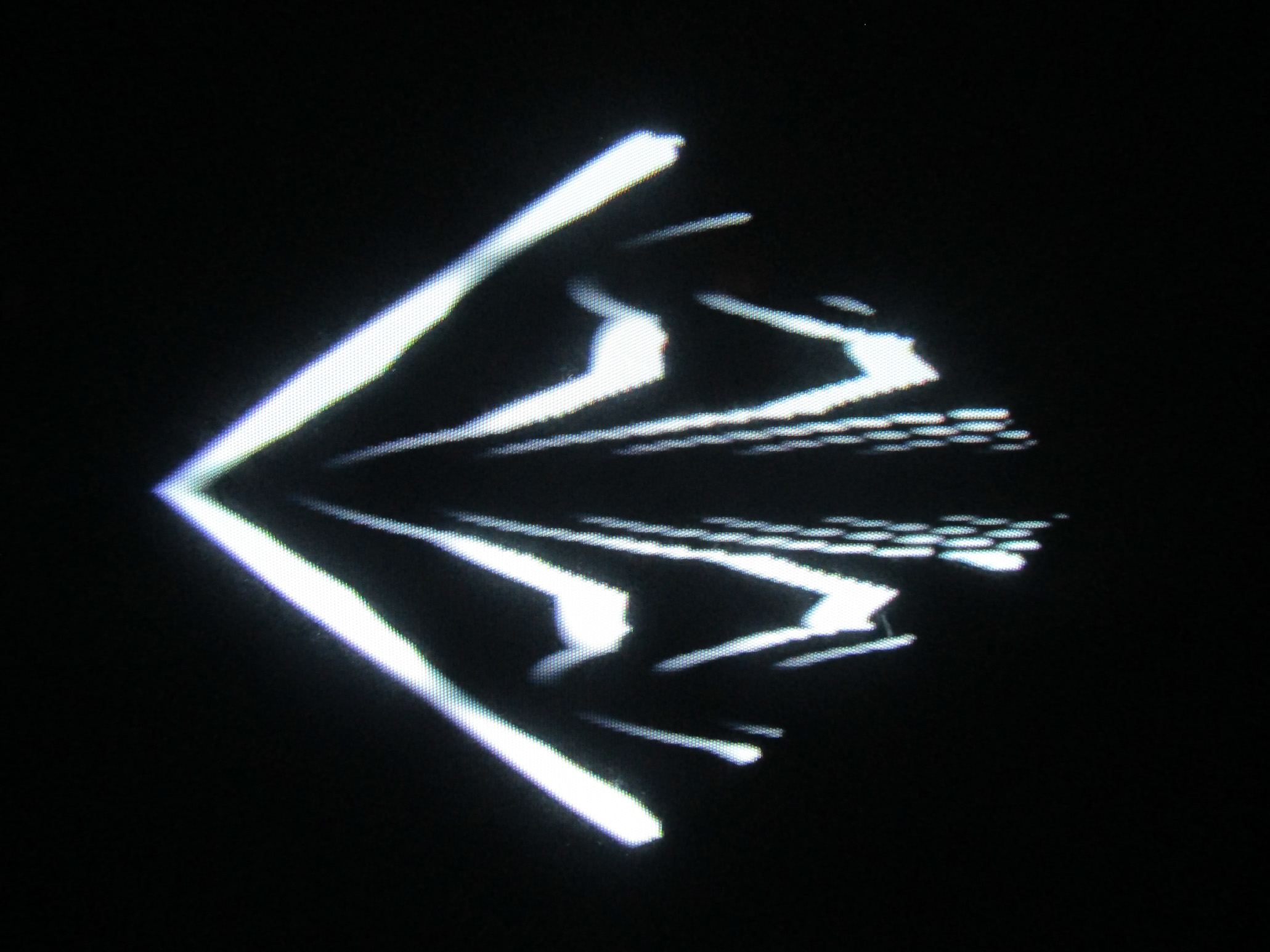
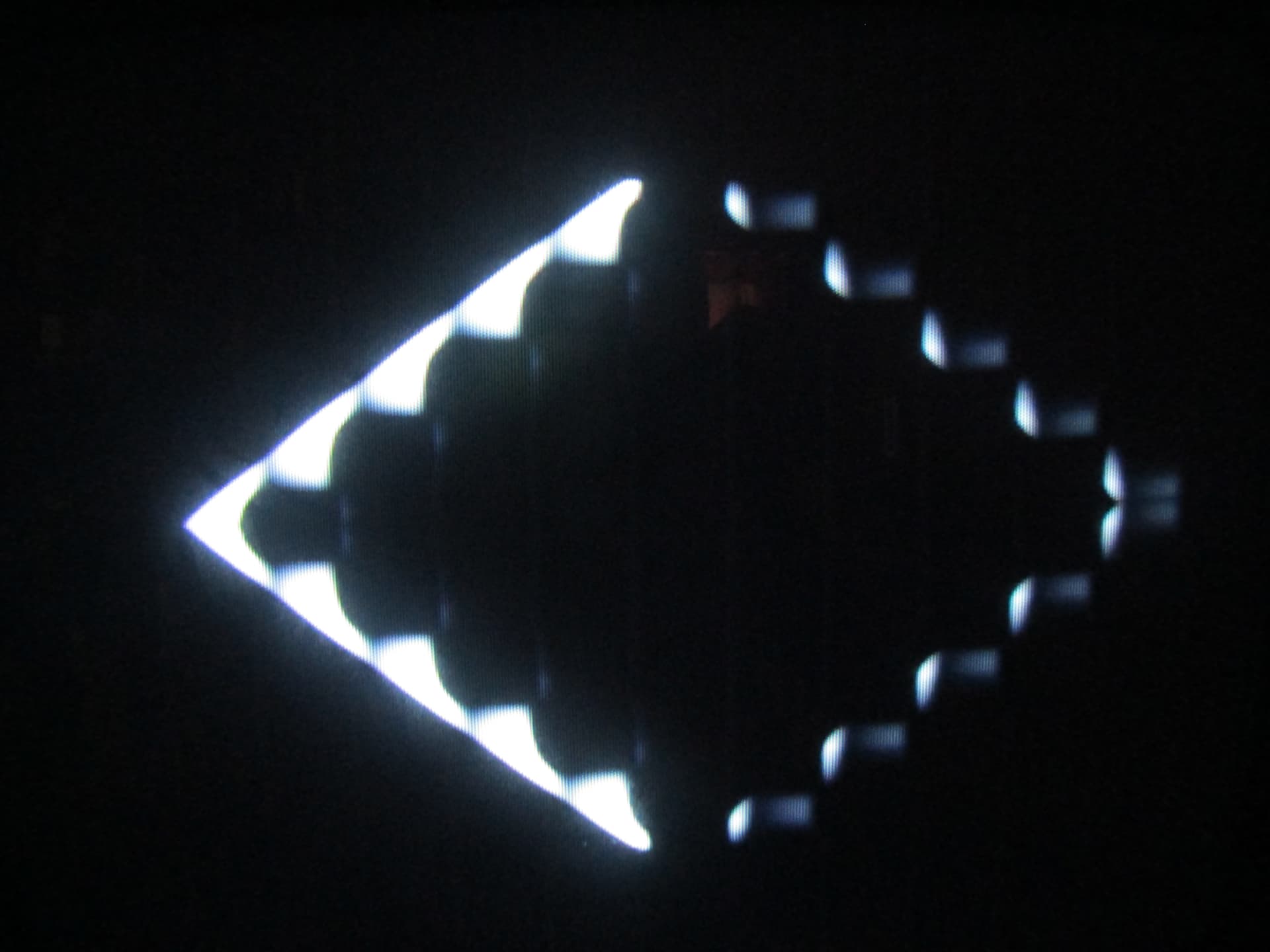
first screenshots (photos of the CRT) of proto v2
the input is a hard edged diamond shape (2 ramps into a Hardkey Generator),
modulator is a Cadet VCO with H or V lines selected.
A large range of iterations is possible, so that is cool.
I have to finetune a lot of functions and test everything, but it looks pretty already!
#47 — reverselandfill · 2022-02-15
A bit of a breakthrough today! I needed that.
the new and simplified breadboarded schematic now works as intended
So I’ll do one last proto and then maybe add some features I’ve been thinking about …
routing 1 2 3
#48 — reverselandfill · 2022-03-11
the new proto is working. I’ll add a hard clipping stage because the cool patterns need higher voltages
I’ll probably use the clipping stage of the LZX Encoder.
The bottom (-v) is already clipped correctly by a 1n5711 diode inside of the mixer stage
new feature set:
Potmeters:
neg mix
pos mix
gain
cv att
switch
edge width
jacks
input
CV
output
#49 — reverselandfill · 2022-04-06
ok, another prototype, v4c
things are almost good now. it needs some minor fixes.
I’ll test more this weekend
The output looks really cool. lots of sweet spots

#50 — rempesm · 2022-04-06
Really glad to see this coming to fruition, would be cool to see any other captures you’ve found during recent testing!
#51 — reverselandfill · 2022-04-06
yes, I’ll make some recordings in the weekend
just a minute ago I made myself look like Pinhead
camera input → edge modulated with several horizontal bars = spikes!
I’ll experiment with several highpass caps to see what works best / edge width
#52 — reverselandfill · 2022-10-06
finally some updates!
v5 works, it has some really nice results. with a middle ground between controlled rounded feedback and glitch
the added send/return path for the feedback is pretty cool
I had a few new ideas for this module (expanding it with more inputs and filters)
so it is an ongoing project
#53 — cburst · 2022-10-11
i’d love a kit when this is ready! keep up the great work!!
#54 — thenoiseoftime · 2022-10-12
Me too super curious!
#55 — Tim · 2023-01-25
Also super excited about this amazing project and would love a kit/pcb/gerber whenever it’s ready! <3 Very close to finishing the Cadet build…it’s been a bit of an Everest for my neuroverge ass but it’s coming together:) Also as an aside anybody privvy to cheaper stock of lt1251’s r lt1256’s that arent a bajillion dollars a unit (well $16)? Cheers and excited for this project!
#56 — rempesm · 2023-01-25
Octopart is your friend but you can always expect LT125x to be expensive compared to most other ICs used in DIY video modular.
#57 — Tim · 2023-01-25
Thank you for the swift reply! Yeah I definitely figured. Off to mouser :)))
or Octopart! (first time hearing of it! cheers)