Triple Function Generator project
Category: Unknown · Tags: — · Posts: 82
#1 — reverselandfill · 2019-04-18
Project description:
I want to make a Triple Function generator based on the Sandin/LZX design.
The function generator is very cool if you use it to re-colorise the B/W Luma input .
Especially with camera feedback, this gives very beautiful results.
Each generator stage can be used individually too.
Features:
- 3x shaper for re-colorizing the B/W Luma video input and other processing
- normalised inputs
Options:
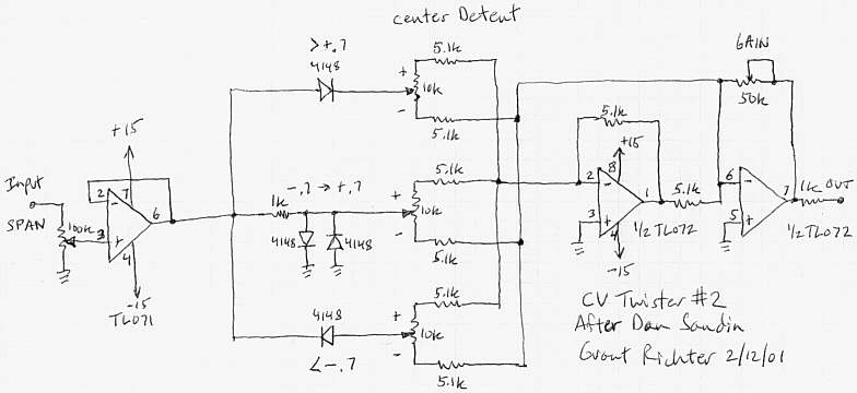
- extra gain & span pots? See Grant Richters adapted schematic below - to be tested
- main pcb + control pcb + panel pcb
- feedback? - to be tested and checked if this is interesting.
- CV control? if this is possible. please help!
Note: this project is directed towards DIYers and is open source.
#2 — reverselandfill · 2019-04-18

basic layout , gain to be tested
#3 — wednesdayayay · 2019-04-18
so I love the function generator too! these are fantastic modules I have an idea though…
how about a single function gen whose three levels are normalled to the inputs of function generators 2-4
input into function gen 1
High band (from function gen 1) out into function gen 2
mid band (from function gen 1) out into function gen 3
low band (from function gen 1) out into function gen 4
I am in no way electronically inclined so I’m not sure if that is how this circuit works at all
I’m following along with this one too
#4 — reverselandfill · 2019-04-19
I’ll probe the circuit at some points, let’s see if I can tap certain stages and give them a output.
#5 — reverselandfill · 2019-05-15
I had an idea:
option 1:
single pcb + a single FG panel
option 2:
3x single pcb + a triple FG panel
I have the layout of this direction done. I just have to make the panel pcb’s
I might add some extra functions, I have to test those first.
For the triple option, I want to have some normalled connections, which can be achieved by interconnecting the pcb’s (the “NORM” pads)
The pcb’s use right angled 9mm pots and are relativly shallow when mounted to the panel. (3.5cm)
ps: if anyone has a footprint of a rightangled dpdt switch, let me know!

#7 — reverselandfill · 2019-05-15
look at my Differentiator VC feedback project page.
I want to aim that project more to a “newer” idea. If I also want to make it triple, it will become a very big project that cannot be made easy in TH parts I think (or it will have several pcb’s sandwiched together.)
But I will keep it in mind

maybe it can be done?
#8 — a_digital_index · 2019-05-16
I have 3 Funk GenZ and can confirm that the fun factor is high.
#9 — reverselandfill · 2019-05-16
Indeed

especially with colorising video input in a feedback setup , amongst other uses
#10 — reverselandfill · 2019-05-28
I’m working on the triple panel now. it is 16HP right now.
pot & jack positions will change , because I might add a pot in the design.
(and I have to check if the panels will fit sideways. )
work in progress


#11 — reverselandfill · 2019-06-04
a more final design. (almost)
sideway mounting fits. 14HP

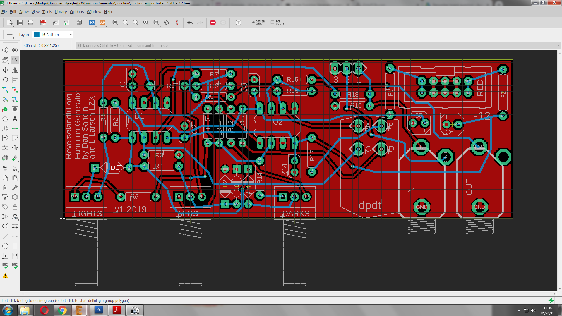
#12 — reverselandfill · 2019-06-28
pcb design almost done.
changes:
-connection holes for normalisation
-dpdt pads placement

#13 — transistorcat · 2019-06-28
Those bottom layer traces up top are a bit too close to the board edge, and D4 might be closer to the MIDS pot than ideal, but appart from that this is starting to look good.
Would you be adverse to re-annotating the board? I find that it generally makes assembly a lot easier, especially if you’re not too familiar with the design.
#14 — reverselandfill · 2019-06-28
the DRC check reported no errors, so I think it is ok.
what do you suggest as for the re-annotating? part values?
Normally I will make a detailled build guide + BOM
I just ordered the pcb’s, so I can still change things
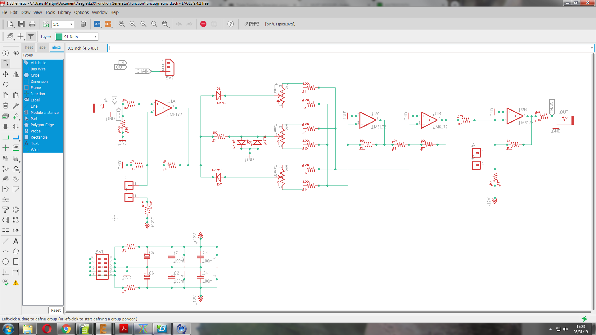
#15 — reverselandfill · 2019-06-28

traces and diodes moved.
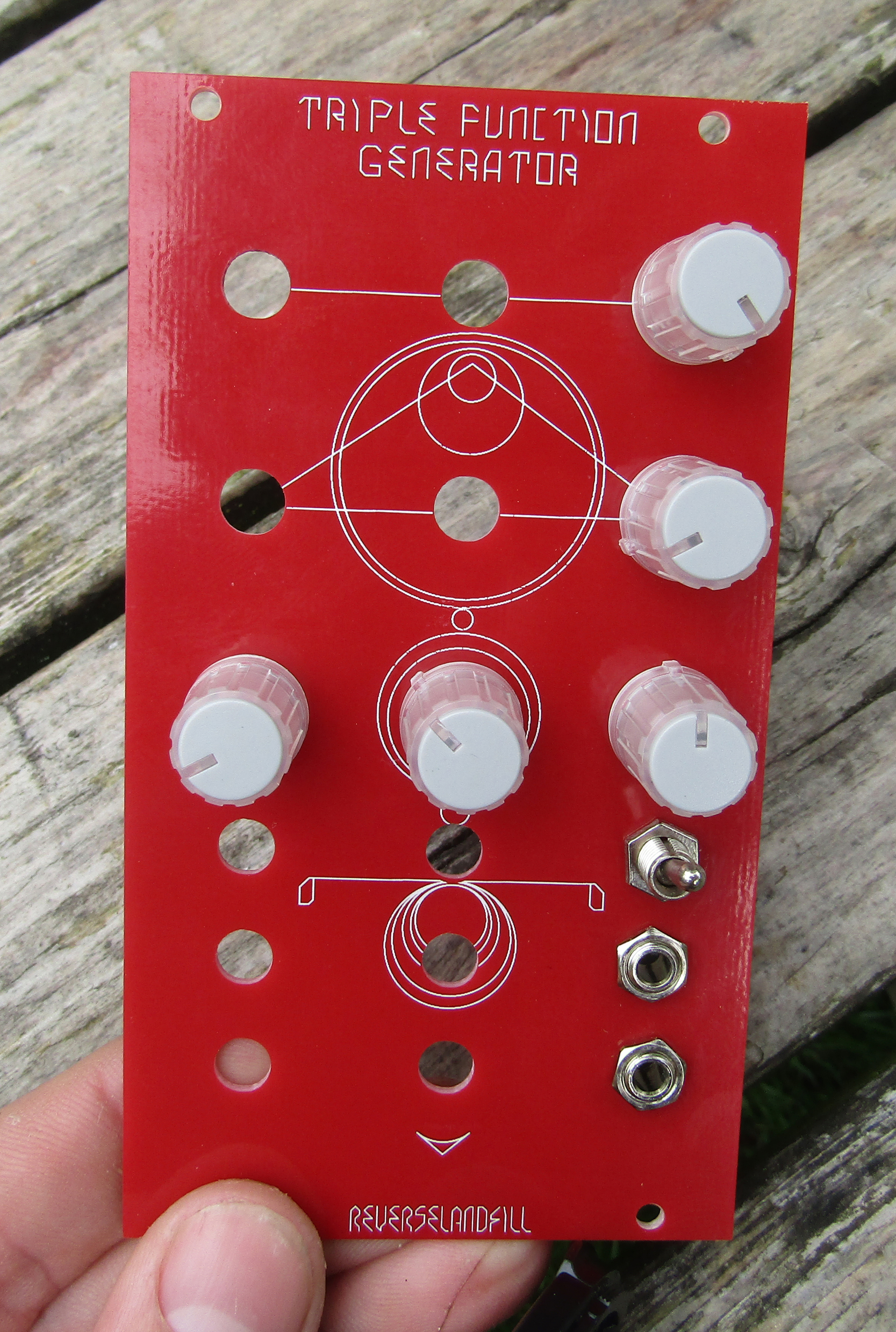
final schematic (for now) - another experimental pcb will be made to explore functions described in the 1st post.

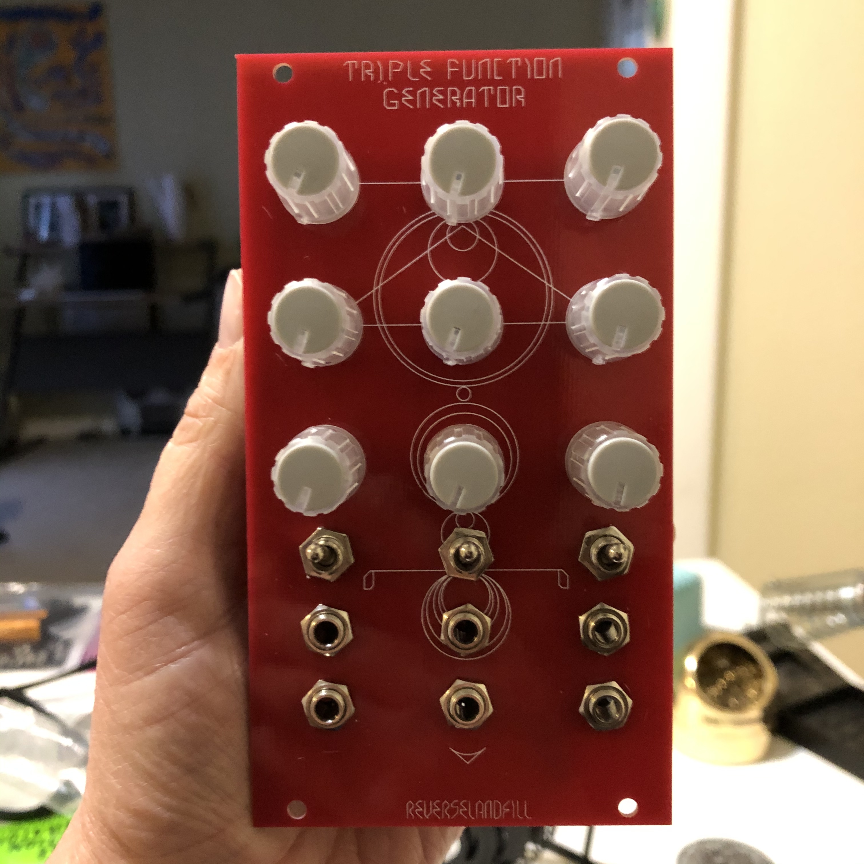
panel look. red!

#16 — transistorcat · 2019-06-28
Re-annotation by position, i.e. updating the designators such that they increase along the board.
It’s just one of those small things, so if you’ve already ordered boards i’d just leave it as is.
#17 — reverselandfill · 2019-06-28
ah, ok.
I will do that. then it will become less of a puzzle.
and done (manually, because the Eagle ULP sucked)
#18 — reverselandfill · 2019-06-28
note:
I just made a cool feedback test patch with 1x function generator + 2x processor.
This gives very interesting results, although it needs much adjustments.
Chaining, as opposed to splitting the input signal, is also very useful.
This can be achieved with the normalisation pads. maybe it is a good idea to make an expansion panel with some switches to change between these routings. I’ll leave that to you DIYers
#19 — reverselandfill · 2019-07-08
the pcb’s are now on its way to me …


#20 — reverselandfill · 2019-07-12
And they are here! The panel looks really cool in red

I will build one , if it works, I’ll make an ORDER thread!
I have 24 FunctionGenerator pcb’s and 22 panels. you need a set of 3 for each panel so I have 8 sets for now.
you can also make a single one and diy the panel.
We will see how it goes


#21 — wednesdayayay · 2019-07-14
is this batch going to be for DIYers only?
#22 — sean · 2019-07-14
If all goes well, I assume you will eventually order more PCBs so everyone can get in on the fun?
(I’m just assuming the initial batch will go quickly. I know I’m definitely interested.)
#23 — reverselandfill · 2019-07-14
yeah, that was the plan.
coming week I’ll be soldering & testing the pcb’s.
I’ll make a separate thread for orders and BOM / buildguide information.
#24 — reverselandfill · 2019-07-15
the main focus is DIY. I might consider to offer build modules.
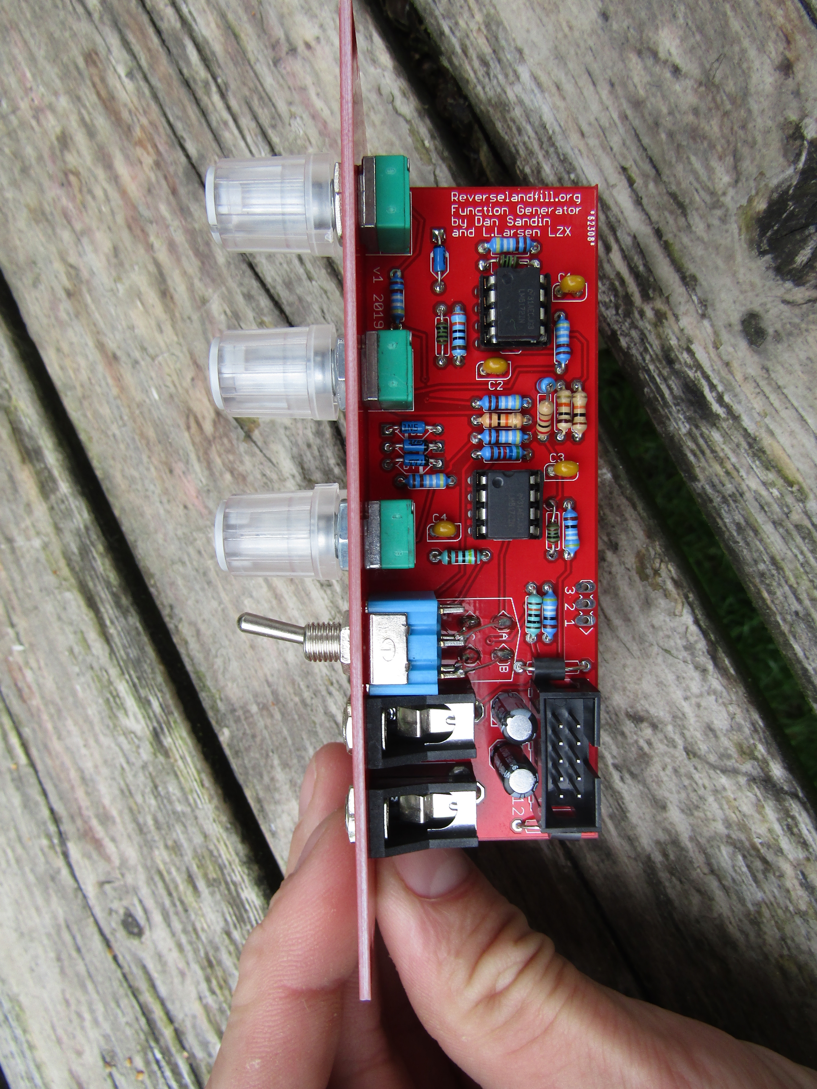
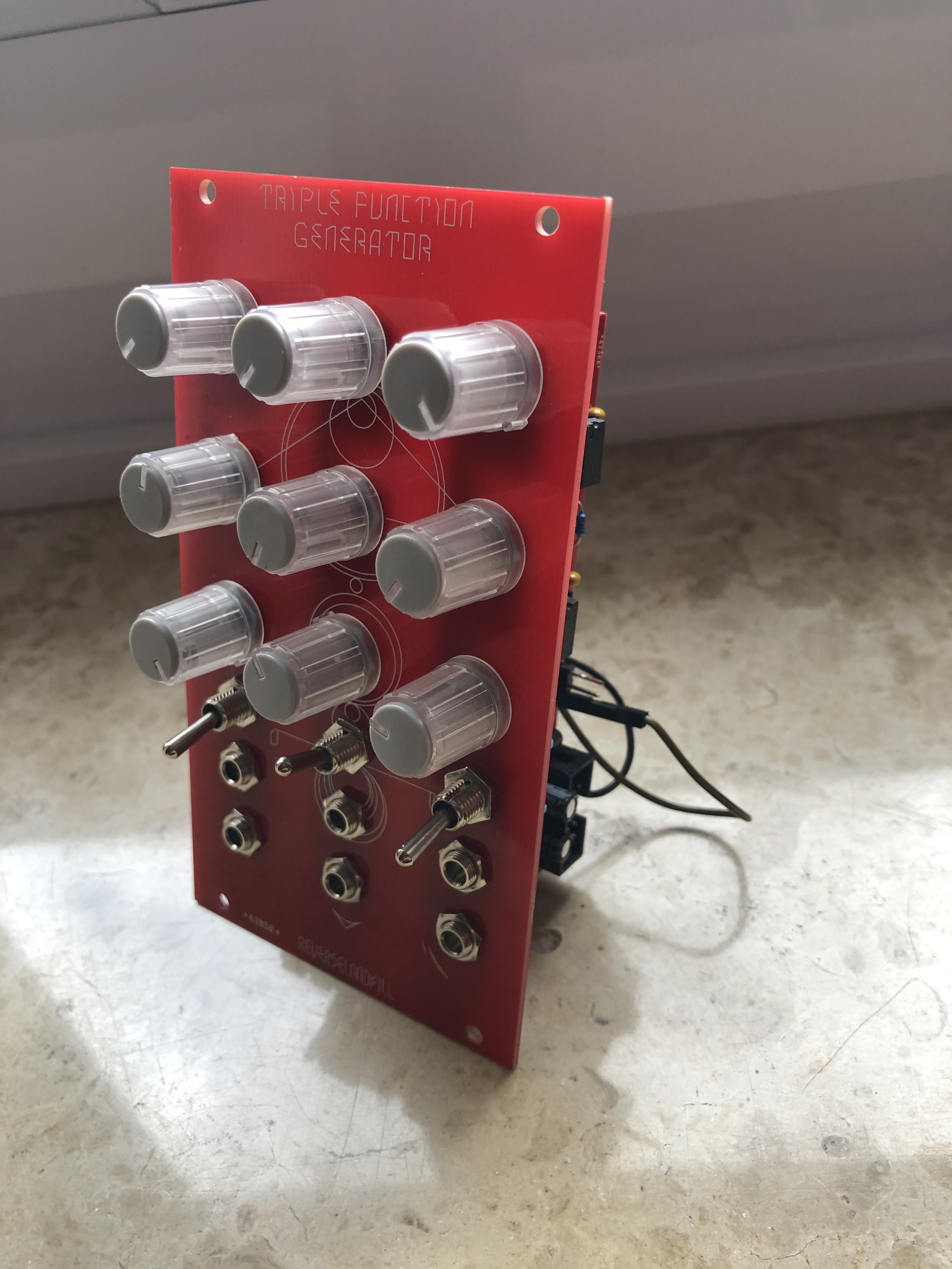
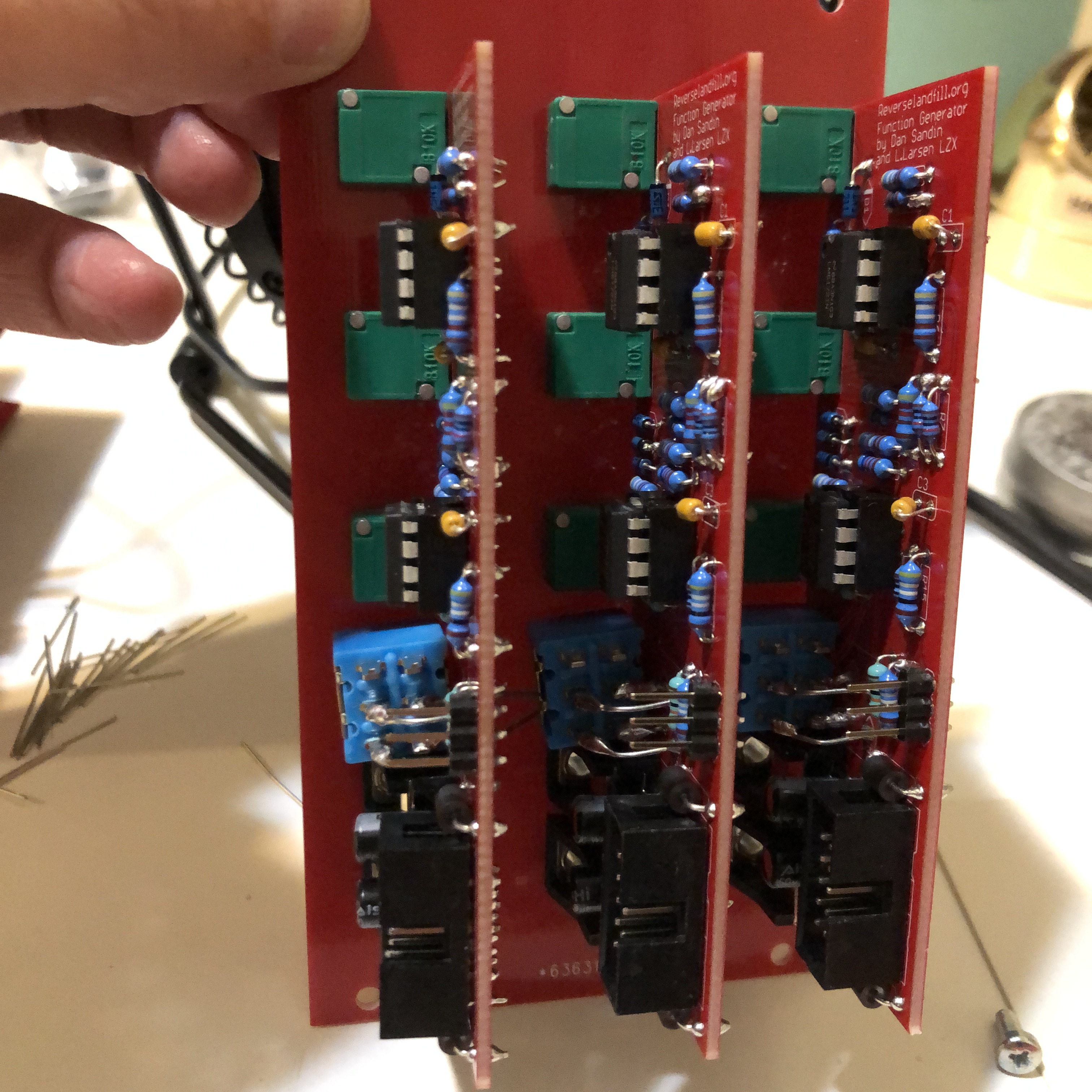
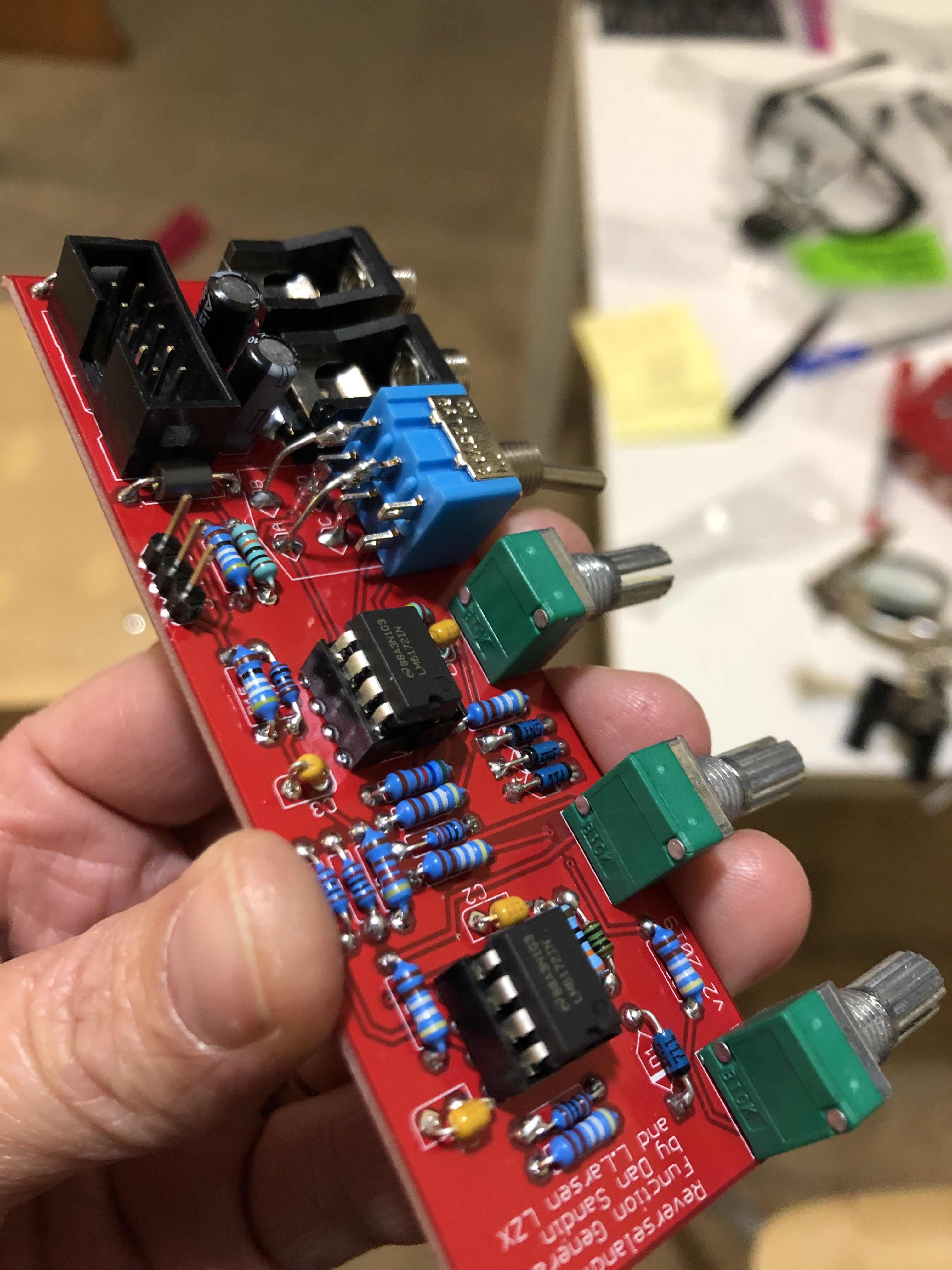
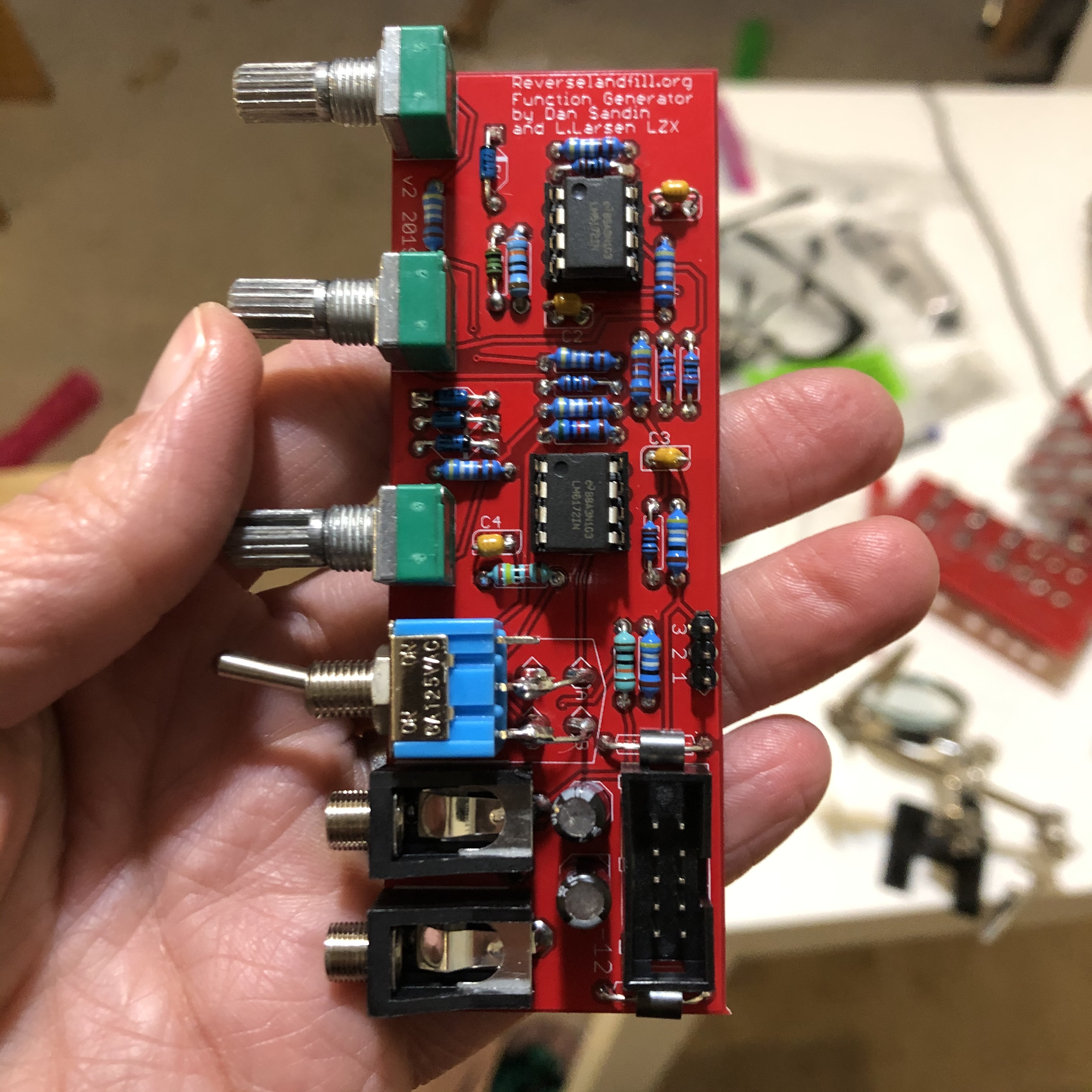
#25 — reverselandfill · 2019-07-18
First test = OK
the pot distance is good. - that is why I have the 5 knobs installed in pic 2.
the switch is a bit close, but not too much. You can solder the ‘default’ setting to the down position.
The PCB is designed to handle the cheaper ‘lug’ type DPDT switch.
You can solder clipped resistor leads into the lugs and holes.
I might search for a DPDT pushbutton solution. tips anyone?in the mean time, I declare this project “READY”!
note: 20 more sets are ordered
#26 — reverselandfill · 2019-07-22
Let’s make the build thread here.
updated BOM 25-07-19
Triple Function Generator BOM version 1 – 2019Boards:amountPCB3Panel1Resistorsvaluetotal of 3 pcbsr1, r5, r6, r10, r12, r144.99k18r2, r161k6r3330r3r4100r3r7, r8, r1110k9r94.2k alternative: 4.32k3r135.66k alternative: 5.6k or 5.62k3r15, r18499r6r1724k3r19100k3Diodesd1, d2, d3, d41n571112Ferritef1, f2ferrite bead. alternative: 10r6Capacitorsc1, c2, c3, c4100nF 2.5mm ceramic12c5, c610uF electrolytic6ICu1, u28pin socket6u1, u2LM61726PotmetersLights, Mids, Darks10k lin 9mm right angled9knobs9Switcha, b, c, dDPDT on-on3JacksPJ302M6Power10 pin shrouded headeror unshrouded310 pin to 16 pin power cable3or use a multicable1Normalised inputsconnect pin 1 on pcb1 to pin 2 on pcb2wireconnect pin 1 on pcb2 to pin 2 on pcb3wire
#27 — Agawell · 2019-07-22
reverselandfill wrote:
or use a multicable
Hi
to make this do I just crimp 3 * 10 pin headers along the length of an idc cable??? so a 16 at one end (for the bus board) and then 10 then 10 then a 10 at the other end??? (10s for the modules)
Jim
#28 — reverselandfill · 2019-07-22
yeah, that is what I meant!
#29 — Agawell · 2019-07-22
Exellent thanks Martijn
#30 — reverselandfill · 2019-07-22
tip: if you use cheap fake LM6172 ic’s , you get funky blurry outputs!
tip2: Ebay sucks at certain times…
#31 — joem · 2019-07-24
Hmmm… Do I sense a LM6172 group buy coming on???
#32 — pbalj · 2019-07-24
I would get in on that
#33 — reverselandfill · 2019-07-24
I could set this up. (with prepayments)
Mouser pricebreaks: (ex VAT)
[1:]€ 4,23[10:]€ 3,80[100:]€ 3,11[250:]€ 2,92[500:]€ 2,65
#34 — sean · 2019-07-24
I’d probably get in on this too.
#35 — reverselandfill · 2019-07-24
see here:
Hey > There was some interest in doing a groupbuy for LM6172 IC’s > If we can get to 250 or 500 pieces, it will become interesting. > If you ordered a pcb (set) of the Triple Function Generator with me, > I can send them along without extra cost. > If not, I don’t know if the shipping cost will be too much - this will depend on how much IC’s you want. the weight… > Best option is Mouser, because they pay the taxes & shipping > Mouser price breaks: >>>>> [1:]> € 4,23>>>>> [10:]> € 3,80>>> [100:]> € 3,11>>> [2…>
#36 — reverselandfill · 2019-07-25
I’ve updated the BOM with alternative resistor values and switch info
#37 — csboling · 2019-08-31
I just noticed that the pads for normalling the inputs together have (unless I’m mistaken, tried this out with an IDC power socket since it’s what was handy) 2.54mm pitch, so if you solder on right-angle pin headers you could use jumper wires to select how the normals work rather than permanently soldering wires to them. Awesome! I’ll have to order some headers.
#38 — reverselandfill · 2019-08-31
yes, idc will work. or dupont pin headers.
You have version 1 on the pcb
1: IN-------- (tip of the input jack)
2: OUT----- (switch of the input jack)
3: GND
Parallel:
connect pin 1 on pcb1 to pin 2 on pcb2
connect pin 1 on pcb2 to pin 2 on pcb3
Version 2 has this:
1: IN-------- (tip of the input jack)
2: OUT----- (switch of the input jack)
3: CHAIN—(tip of the output jack) This is for routing in series and parallel.
Parallel: (one input source gets routed to all three inputs.)
connect pin 1 on pcb1 to pin 2 on pcb2
connect pin 1 on pcb2 to pin 2 on pcb3
Series: (the output gets routed to the next Function Generator input, three in a row)
connect pin 3 on pcb1 to pin 2 on pcb2
connect pin 3 on pcb2 to pin 2 on pcb3
@csboling: you can still route the boards in series if you would like to. Just wire it from the output jack.
I can make a drawing if you need it.
#39 — reverselandfill · 2019-08-31
version 2 schematic.
note: the BOM remains the same. If you want ‘modular’ routing, add pinheaders & cables as needed
#40 — VanTa · 2019-09-14
my only question would be,
how do you people clean the pcbs?
I use 99% isopropanol and a toothbrush, but at the end it always ends up with a sticky residue.
#41 — reverselandfill · 2019-09-14
The same as you. sometimes I use a toothpick or flat screwdriver to remove flux blobs.
#42 — Dewb · 2019-09-15
Some earlier discussion on PCB cleaning:
What are other DIY’ers doing for board cleaning? No-clean flux and forget it? Rosin-core and IPA? Ultrasonic baths? > My practice in the past has been to use 99% IPA, a tupperware tray for soaking, and an old toothbrush, but I recently switched to this Sparkfun lead-free solder with a water-soluble flux. >>> IPA doesn’t do a very good job on this, and I finally tracked down the manufacturer recommendations on the flux, which is to water-wash without cleaning agents: >> [http://documents.indium.com/qd…](http://documents.indium.com/qdynamo/download.php?docid=373)
#43 — transistorcat · 2019-09-16
I do nothing cleaning-wise, and i’ve never had any problems.
YMMW wrt. flux use, of course.
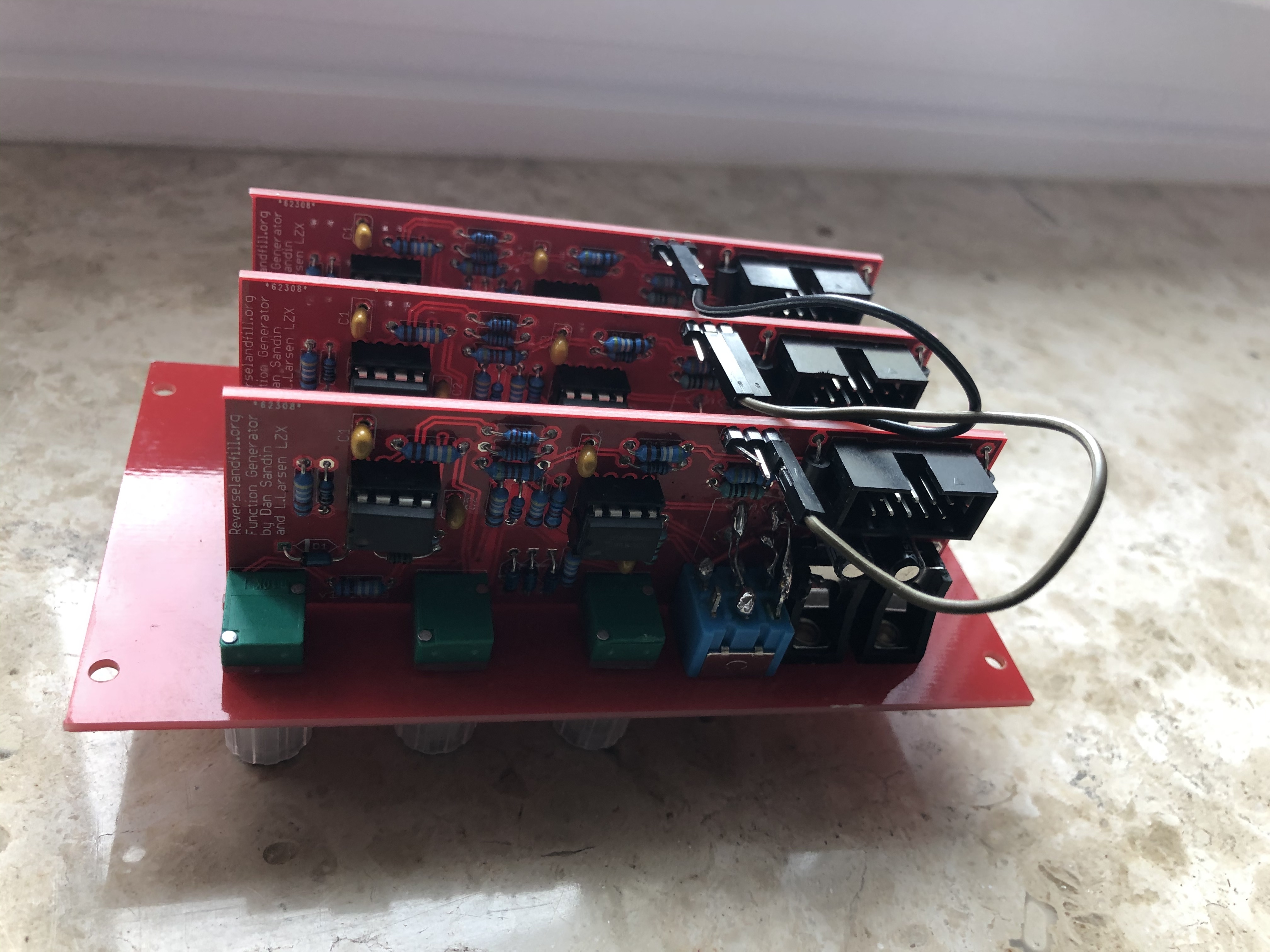
#44 — synlog · 2019-10-03
Two pictures from the TFG:
#45 — dondon · 2019-10-06
My PCB kit arrived last week, still trying to track down a couple of components though.
With the 4.2k resistor, 4.32k is listed as an alternative; I have 4.3k resistors on hand, would they work as well?
#46 — reverselandfill · 2019-10-06
jup!
4.2k is hard to find, so anything that comes close is usable
#47 — addamm · 2019-10-10
Question on switch wiring - can someone indicate which numbers on the DPDT pinout diagram on http://www.learningaboutelectronics.com/Articles/Toggle-switch-wiring.php
correspond with A B C D on the pcb? Thanks!
#48 — reverselandfill · 2019-10-10
the dpdt switch has 2 rows of 3 pins.
1 2 3
4 5 6
connect A & B to row 1 (2 & 3)
connect B & C to row 2 (5 & 6)
the switch makes or breaks a single connection between A & B and C & D
So two of the pins are not used, they are ‘open connections’
#49 — addamm · 2019-10-10
Just finished one channel of my build. My video setup is still a work in progress but this makes a fun waveshaper/folder(?)/rectifier for audio, especially when gradually adjusting audio input level before going into the TFG
#50 — reverselandfill · 2019-10-24
The buildguide is almost done, sorry for the delay!
#51 — reverselandfill · 2019-10-24
and here it is: (as PDF downloadable) https://www.reverselandfill.org/diy/triple-function-generator-project/
direct link:
reverselandfill.orghttps://www.reverselandfill.org/wp-content/uploads/2019/10/TFG_v2_buildguide.pdfhttps://www.reverselandfill.org/wp-content/uploads/2019/10/TFG_v2_buildguide.pdf3.20 MB
Link: TFG_v2_buildguide.pdf
#52 — VisibleSignals · 2019-10-26
Hi Martijn,
Could you comment on the intended function of the toggle switch?
By my reckoning it looks like when in the A-B position it increases the bias of the first op-amp’s negative input (i.e. moves the virtual ground slightly higher) and when in the C-D position it adds in a little bit of negative bias to the input of the summing last op-amp.
So I think the two switch positions shift the output voltage level, and change the position of the three adjustable bands slightly, which is essentially confirmed by what I see on my scope. Is that right or have I missed something?
EDIT: Never mind, I’ve worked out that it’s a bipolar/unipolar selector, switching the midpoint between 0V and 0.5V. It all made sense when I scoped it with a +/-1V ramp wave input rather than a +/-12V sine
#53 — reverselandfill · 2019-10-26
the switch sets the range of the lights-mid or mid-darks
just plug in a video camera source and you will get it
-> by adjusting the pots I mean
#54 — reverselandfill · 2019-11-06
fixed the buildguide, thanks @GijsvO
the R4 / 100r resistor was not in the guide, now it is

#55 — Genlok · 2019-11-07
Are there any videos of this module in action yet?
#56 — joem · 2019-11-08
Just open this up in three tabs: https://www.youtube.com/watch?v=ensZd7VvbTw

In all seriousness though, the Sandin IP Function Generator module in that clip is what the Triple Function Generator is based on. The Triple Func Gen just has 3 of them in one module. I can’t remember if there’s any normalling or not. Still, I’d definitely like to see someone using a Triple Func Gen on R, G, and B channels, so hopefully someone posts something!
#57 — Genlok · 2019-11-08
Yeah, that’s kinda what I was getting at, using all three in parallel or series for colorization or feedback. Need to see that
#58 — reverselandfill · 2019-11-08
I’ll try to make a video of this tonight
uploading to video right now. but internet is slow here …
#59 — reverselandfill · 2019-11-08
here it is:
patch info:
Camera -> sync generator -> video input -> TFG -> RGB encoder
I play with the brighness and contrast levels in the beginning of this movie, this has a lot of effect on the color shades and ranges.
For the rest I play with all the knob settings and switches to explore the different color values and inversions.
note: the scrolling color if the result of my crappy CCD camera, not the module.
#60 — rempesm · 2019-11-09
Thanks again for making this project a reality, Martijn–really digging mine in a very similar patch as above and looking forward to the matrix mixer!
#61 — Bouncy · 2020-01-02
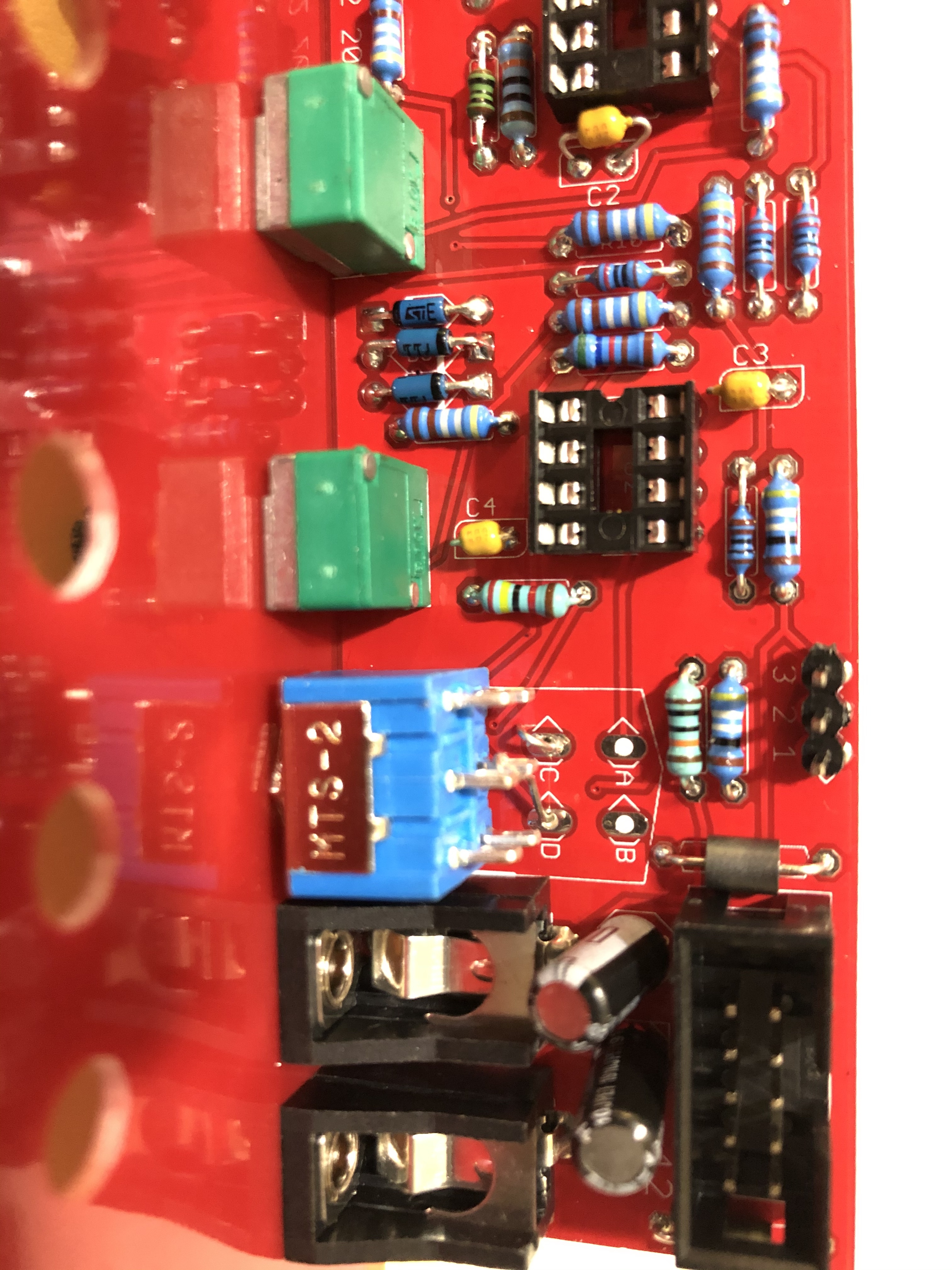
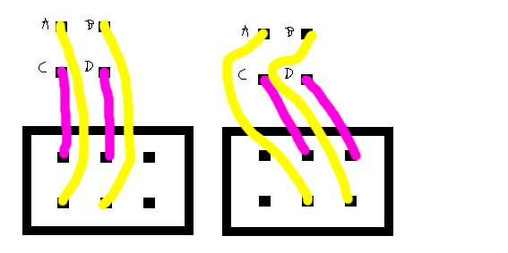
Hello! I have a question about the pin connection on the switch. My reading of the build doc makes me believe that I have to crisscross the leads coming from 1 & 2 and 4 & 5 (see my drawings pictured below please).
Based on your comments above, I think I really just need to match up A & B with 1, 2, or 3 and C & D with 4, 5, or 6.
Am I understanding this correctly?
Thank you in advance for the help! Trying to get this project done before I have to go back to work. Great build project!
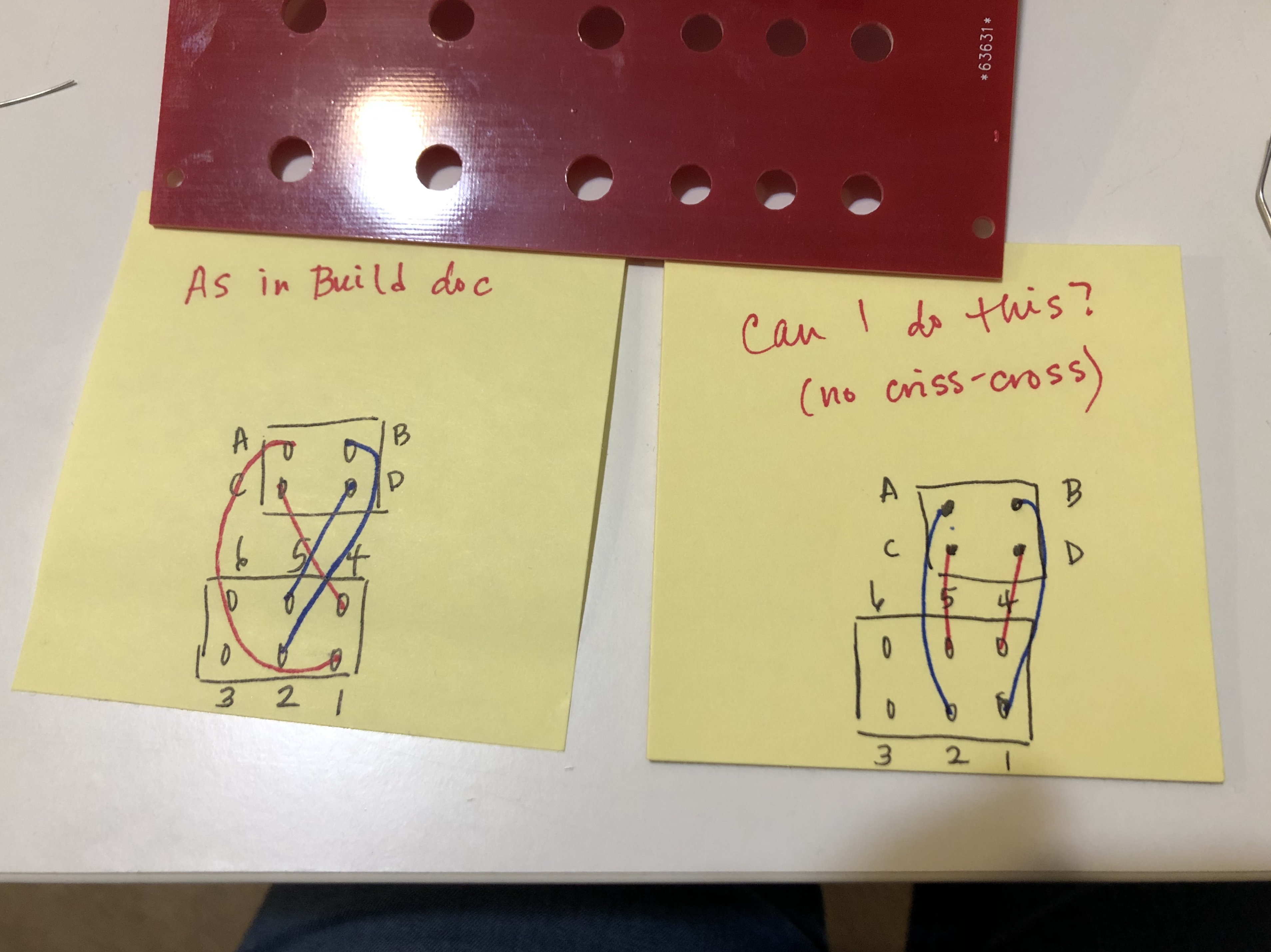
#62 — transistorcat · 2020-01-03
Those two drawings are electrically equivalent, but i think you may be trying to mount the switch the wrong way around. This would reverse the direction of the switch paddle,
Since the panel is unlabeled this is not all that problematic, but if you’re worried using coated wire of sufficient length would allow you to turn the switch around later.
#63 — reverselandfill · 2020-01-03
you can look at A and B as an on/off connection.
The switch makes a connection with 1&2 or 2&3 + 4&5 or 5&6
So you can solder it as shown in the picture.
The build doc says this:
Mount the DPDT switch to the panel. Use resistor leads to solder PADS A, B, C, D.
The switch looks like this: six pins, in rows of three.
1 2 3
4 5 6
Solder pad A to ‘1’ , pad B to ‘2’ , pad C to ‘4’ , pad D to ‘5’.
So both drawings are correct.
But the switch does not have a direction, so you could also connect A to ‘3’ and B to ‘2’,
or A to ‘2’ and B to ‘3’
#64 — Bouncy · 2020-01-03
Thank you very much for your response. I used coated wire that I had on hand. That worked for me. Plus the coated wire is more bendy than the leads, which made it easier for me. Thanks!
#65 — Bouncy · 2020-01-03
Thank you for adding the drawings. I love it! And it is very helpful!
I was making this more complicated than I needed to (probably “as usual”). I have finished up the first TFG and am starting on the second one now.
Thank you for your response and the help!
#66 — Bouncy · 2020-01-04
reverselandfill wrote:
too.
Just sharing some photos of the final version (no jumper cables attached). Thanks again for the help!
#67 — Whelm · 2020-03-04
So I just finished one of these and it’s great. It’s really helping me get some more interesting colour pallets with my cadets.
I had a bit of an issue though with the normalization. Sorry if I’m missing something, it’s quite likely.
I didn’t use jumpers, I just wired it for parallel. When I wired it as per instructions, though, I found that the normalization was not symmetrical. IE, PCB 1 normaled to PCB 2 and PCB 3, but PCB 2 only normaled to PCB 3 and PCB 3 didn’t normal at all.
I solved this by connecting pin 1 on PCB 3 to pin 2 on PCB 1 - ie connecting PCB 3 input tip to PCB 1 input sleeve.
So am I missing something or is there perhaps a step omitted from the normalization instructions?
#68 — reverselandfill · 2020-03-04
the pcb’s are identical, so this should work as described in the manual.
Take a look at the schematics to understand this.
If you patch a jack into one of the inputs, you break the normalisation from that point onwards
I don’t fully understand your wiring explanation. can you descibe it using these terms:
pcb 1 (pin number) -> pcb 2 (pin number) -> pcb3 (pin number)
Also check the soldering on the wiring. use a multimeter to be sure (test the jacks pins for connection)
Version 2 pin ID:
pin 1 = tip of the input jack
pin 2 = switch of the input jack
pin 3 = tip of the output jack (in version 1 , this pin is GND)
#69 — Whelm · 2020-03-04
Sure.
Instructions are:
PCB1 Pin 1 -> PCB2 Pin 2
PCB 2 Pin 1 -> PCB3 Pin 2.
What I added was
PCB3 Pin 1 -> PCB1 Pin 2
IE I connected PCB 3 to PCB 1, without which I was not getting symmetrical normalization.
Without that extra wire, PCB3 IN would not normal to PCB 1 or 2. PCB 2 would not normal to PCB1. PCB 1 would function as expected. IE they were normalizing in a line and not in a circle.
Which I think makes sense? Because without the connection between PCB3 and PCB1, when a jack is inserted in PCB2, the switch of PCB2 is no longer connected to tip. Right? But it’s the Switch on PCB2 that connects with Tip on PCB1. So the signal moves down to PCB3, but not up to PCB1.
I used a multimeter to figure this out. As far as I can tell the jacks are all working as normal.
#70 — reverselandfill · 2020-03-04
The normalisation is setup in the manual as this:
PCB 1 is connected to PCB 2, PCB 2 is connected to PCB 3
so this is a ‘line’ . Patch the input into PCB 1 and the normalisation is spread over to PCB 2 and 3
PCB 1 is the first in line, so this would be the leftmost channel.
Your method makes that you can use any input .
I did not think up this scenario. maybe it is useful in some cases.
#71 — Whelm · 2020-03-04
Ah okay, so it was working as intended. I guess I was just expecting ‘normalization’ to be symmetrical as in a multiple.
You’re right that it’s not really a useful difference. I guess I just like being able to use any input without worrying about which is the main one.
#72 — Genlok · 2020-05-02
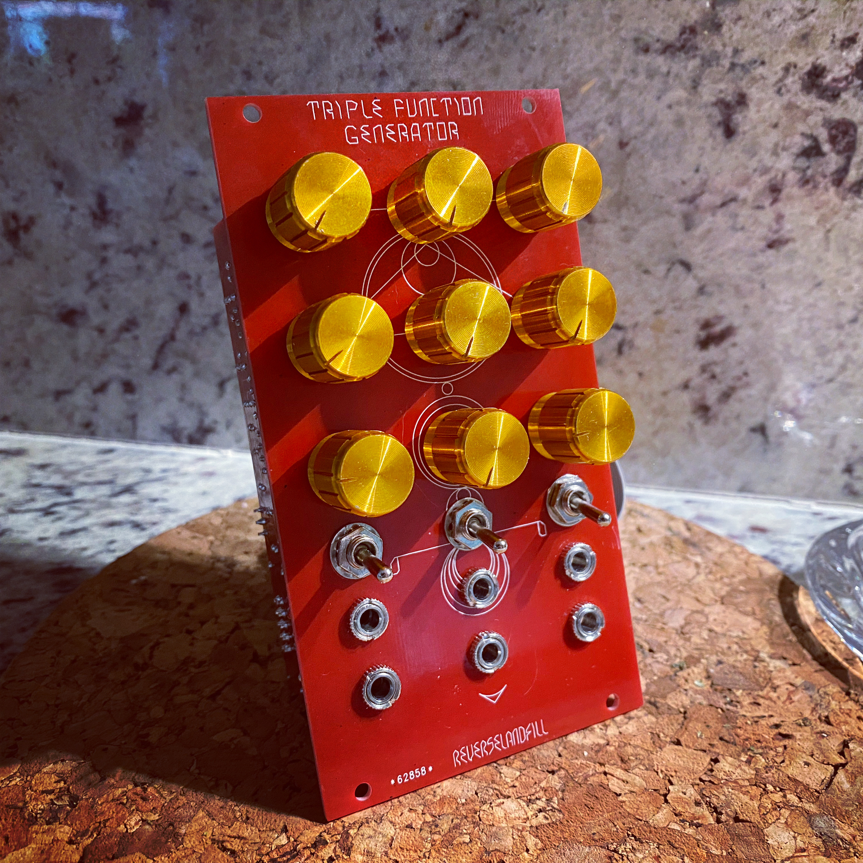
Well after waiting 4.5 months, I finally received my built TFG today. My builder never ordered knobs but had these laying around… I like them! Very different look but they definitely match the front panel.
#73 — reverselandfill · 2020-05-02
wait… did the shipping take 4.5 months?
or your builder?
#74 — Genlok · 2020-05-02
My builder! I gave him the kit the week I got, sometime in December I think
#75 — reverselandfill · 2020-05-03
ok
That panel looks wonderful. I’ll post it on my site.
#76 — kopflastig · 2021-03-29
can i just plug a composite signal in there? or do i need this Cadet Sync Generator?
Are there any alternatives to these Cadet Modules?
How can i get started to all that fun?
#77 — rempesm · 2021-03-30
There’s nothing stopping you from plugging a composite signal in but you likely won’t get the results you’re looking for, e.g. you’ll probably get more glitchy results as you’ll be messing with the image and sync signals at the same time. Generally speaking, you need a genlockable sync generator and an encoder of some form to process composite signals within the LZX universe.
Check out this wonderful thread from @wednesdayayay :
This is all very much a work in progress. > I wanted to collect all the information necessary for someone to dive into video art. > first of all > [everyone is welcome to join the Video art study group](/forum/t/2661/)> [@Zifor](/u/zifor)> and I started a while back just follow the link. No experience or hardware is necessary this is just a video/audio chat about video art we hold every 2 weeks. >> Video fundamentals> The playlist is simple collection of videos talking about analog video. It can be very helpful to understand how the m…
#78 — dryodryo · 2021-12-04
Hey Martijn, I got a couple of these lovely TFGs prebuilt from Schneiders Laden. Question: what’s the safe voltage range? I want to use these for all sorts of things, not just LZX 1V video. Vector graphics, audio, etc. And I don’t want to destroy them with too much voltage.
Currently I’m driving my system with an Expert Sleepers ES-9, which is defaulted to 0-10 V.
Thanks!!
#79 — rempesm · 2021-12-05
dryodryo wrote:
Question: what’s the safe voltage range?
Standard Eurorack rails voltages, +/-12V.
#80 — dryodryo · 2021-12-05
dryodryo wrote:
Question: what’s the safe voltage range?
rempesm wrote:
Standard Eurorack rails voltages, +/-12V.
Awesome, thanks for your help!
#81 — reverselandfill · 2021-12-05
I think you mean the input voltages, not how to power your module, right?
#82 — rempesm · 2021-12-05
This uses all LM6172s, right? It should accept voltages up to the power rails without blowing up. It may not provide expected results to give it 0-10V but it wouldn’t fry anything.
#83 — reverselandfill · 2021-12-06
yes.
As audio modifier, ir works as a sort of wave folding/shaping
for vector stuff, try it out! and post pictures here
