All About Curtain
Category: Legacy Docs · Tags: curtain, eurorack, expedition · Posts: 1
#1 — Z0NK0UT · 2019-07-18
Designed to increase the contrast of the edges of objects, analog video enhancers have a history dating back to early medical and military imaging systems. Doctors have used video enhancers to analyze x-rays, and NASA has used them to process some of the first electronic images of space and the moon. In contemporary times, circuits such as the Curtain module have been replaced by sophisticated high resolution digital image processing, but the visual appeal of time-constant based processing of analog signals remains.
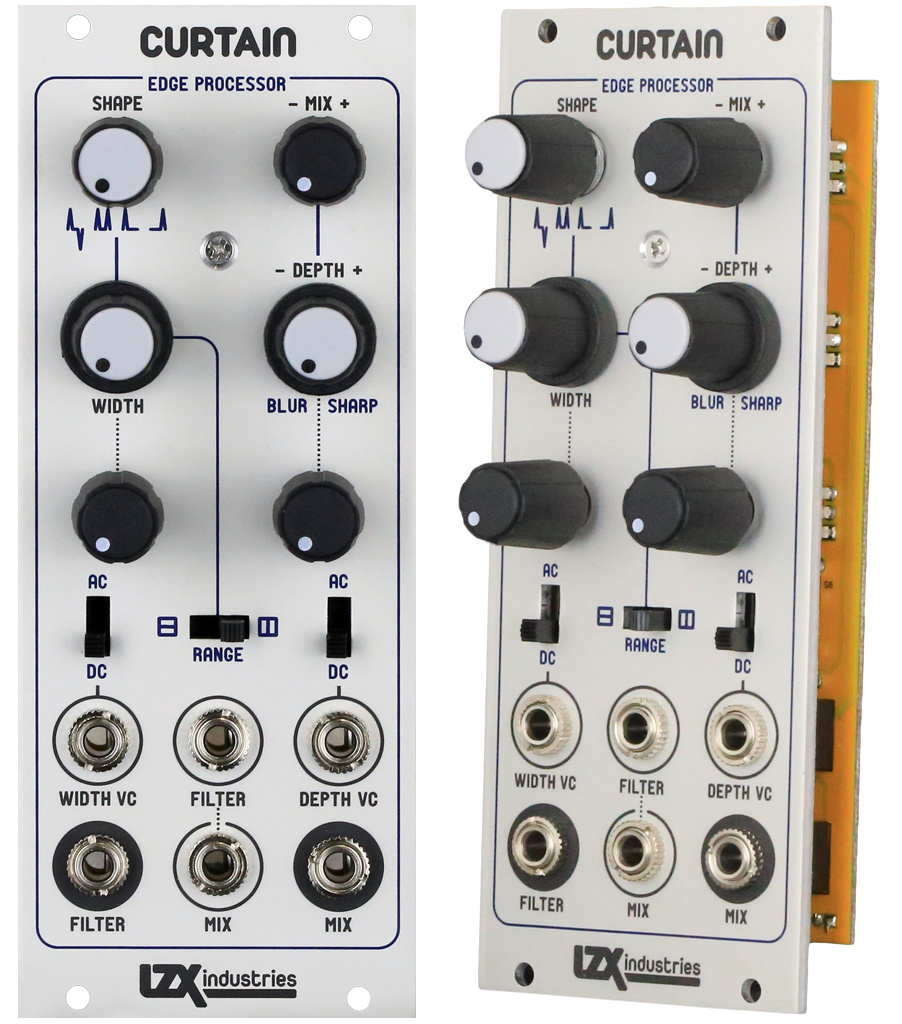
Our Triple Video Multimode Filter module was our first prototype of a video rate, fully voltage controlled filter design. After patching this module in countless ways and thorough study of vintage processors such as the FOR-A IV530 Contour Synthesizer, the signal path for an updated design became clear. Curtain integrates a high pass VCF and a voltage-controlled output mixer which sums the filter output with its original input (or an alternate source.) Since subtracting a high pass output from its input yields a low pass, modulating the inverting/non-inverting depth of the high pass filter into this mix allows one to go from sharpening to blur all on a continuous voltage control. In this sense Curtain controls not only the time constant of the analog processing effect, but also its depth in the output mix.
- Voltage controlled filter with 1:100 continuous tuning ratio allows a full sweep from thin to wide time constants. Three range settings cover a cutoff range from 100Hz to 5MHz.
- Switchable rectifier allows selection of positive rising edges and falling negative edges, both edges positive, rising edge only, or falling edge only.
- Voltage controlled depth allows a continuous sweep of filter output amplitude and inversion. This enables settings from blur to sharpen on a single modulation channel.
- Separate inputs for the filter and output mix allow edge processing from once source and output mixing with another. Dedicated filter and mix outputs allow further external processing.
- All signal and control paths perform at high frequency, video rate modulation speeds.
- AC/DC input coupling switches and inverting level attenuators on voltage control inputs.
Specifications
- Width, 10HP
- Mounting Depth, 32mm
- Power +12V @ 70mA
- Power -12V @ 70mA
User Reference
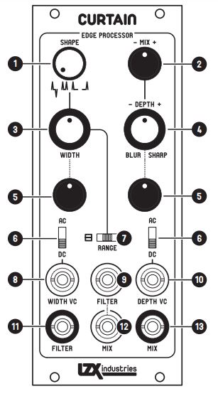
- Shape mode selection switch (4 positions.) This switch selects optional post-processing for the high pass filter. In its initial setting (shown) the high pass filter output is unaffected. In its second setting, falling edge spikes are inverted so that both rising and falling edges are positive
voltages. In the third setting, only rising edges pass through. In the fourth setting, only inverted falling edges pass through. 2. Inverting level control for the mix input jack. This control sets the level of the mix input which is added or subtracted from the mix output. Center is the 0 position. Clockwise from center, and the mix input is added to the mix output. Counter-clockwise from center, and the mix input is subtracted. 3. Width offset control. This control sets the cutoff frequency of the high pass filter. In visual terms, it changes the width of the edge to be processed. Fully counter-clockwise, and the cutoff frequency is at its minimum value (large edge width.) Fully clockwise, and the cutoff frequency is at its maximum value (small edge width.) 4. Depth offset control. This control sets the level and inversion of the high pass filter to be mixed into the mix output. Center is the 0 position. Clockwise from center, and the filter output is added to the mix output. Counter-clockwise from center, and the filter output is subtracted. 5. Inverting level controls. These controls set the depth of external voltage control modulation applied to the associated parameter. In their center positions, the output is 0. Adjusted clockwise from center, the signal is added to the associated parameter. Adjusted counter-clockwise, the
signal is subtracted. 6. Voltage control AC/DC coupling switches. In AC mode, slow moving voltages are removed from the input signal and only high frequency content remains. 7. Frequency range switch for high pass filter. This 3-position switch selects the cutoff frequency range for the high pass filter. In it’s leftmost position, the filter is in the upper end of the audio/vertical range. In it’s middle position, cutoff extends from the beginning of the horizontal
range to its middle point (somewhat thin lines.) In the rightmost position, the range extends to the upper limits of video bandwidth. 8. Width external voltage control input. 0-1V DC full scale. The depth of modulation is set by the associated inverting level control (4). 9. Primary signal input for the high pass filter. 0-1V DC expected. When the mix input (12) is unpatched, the signal input to the filter input jack will be automatically connected to the mix input (12) as well. 10. Depth external voltage control input. 0-1V DC full scale. The depth of modulation is set by the associated inverting level control (4). 11. Direct output from the high pass filter, +/-1V DC variable output. Use this for extending the processing chain to include feedback or other components. 12. Mix input. 0-1V DC expected. When the mix input is unpatched, the signal input to the filter input jack (9) will be automatically connected to the mix input as well. The depth of of the mixed signal is set by the associated inverting level control (2). 13. Mix output. 0-1V DC full scale. This is the primary output of this module, and includes a mix of the high pass filter input and the signal at the mix input.
Videos
Patching Tips
- Play with width, depth, and mix level controls to get a feel for how they interact. Try the different range and shape mode settings.
- Instead of the key generated by the H+V ramp mix, use external video as the input source to Curtain.
- Apply voltage control to width. Ramp generator outputs (from Cortex) and external VCOs make great sources.
- Apply voltage control to depth. Ramp generator outputs (from Cortex) and external VCOs make great sources.
- Try using other shapes and key generator outputs as modulation sources or mix inputs.
- Mix a variable amount of the filter output into the signal being sent to the filter input, to generate feedback ringing and repetitions. Passage is a good module to use as a utility mixer.
- Try patching the filter and mix outputs to separate colors.