3x3 Matrix Mixer Project
Category: Unknown · Tags: — · Posts: 70
#1 — reverselandfill · 2019-07-30
Would anyone be interested in this project?
For some reason I’m really into mixers lately.
3x3 layout … it will be a large project if I decide to do this. 5x LM6172
and I have 1 stage left, maybe an inverted input but that would mean 3 more pots. and there are already 12

Destinations:
- feedback routing
- color mixing.
features: (for now)
- 3x input with 3x pots per channel - so 9 pots
- 3x output with 1x gain pot per channel
Things that might change:
- gain pots: they can be in the feedback loop ? for better amplification / soft keying?
- inverted inputs without pots. IDK if that is useful, but it would save panel space
- SMD? maybe?
I’m open for idea’s!
#2 — Agawell · 2019-07-30
well I was just thinking about buying a doepfer matrix mixer - as there were no diy ones I could find that I liked
so why not
conditional add to group buy - if you do this I need 5 more
cheers
Jim
#3 — mwmw · 2019-07-31
Yep definitely interested in this!
#4 — creatorlars · 2019-08-01
Schematic looks OK – but make sure you ground the noninverting input on the unused opamp, and connect a 1K resistor from inverting node to output. That way you won’t get any potential ringing or oscillation from the floating terminals.
#5 — reverselandfill · 2019-08-01
I might want to use that last opamp for something more useful, that is why it is still floating

Maybe I’ll add a inverted input, or at least a mod input for expansion possibilities. to keep the DIY blood flowing!
#6 — Analogmonster · 2019-08-02
I can definitely see me wanting at least one of these please yes
#7 — 743v04 · 2019-08-02
Also Interested! Nice work @reverselandfill
#8 — reverselandfill · 2019-08-02
Thanks!
These modules are not the most exiting things you could think up (as opposed to filters, effects and oscillators) but it is where I am right now in my personal electronics development. I’m mostly building on opensource schematics by LZX and others, adding some features I think might be useful. The help from @creatorlars is invaluable!
And I do think it is cool to have more DIY video projects in the ever expanding universe of modular !
#9 — DataGeneral · 2019-08-06
Hey, what’s up? I have been working on something like this too. I was doing a 4x3 matrix. I just got access to a desktop milling machine, so I was going to prototype it.
I have another surface mount variation using a max4392. I’m willing to distribute whatever and collab if anyone is interested!
#10 — DataGeneral · 2019-08-19
As mentioned in the previous 2x2 mixer thread, I am now finding that yes…buffers are our friends. Rev 2 Doh!
#11 — giantmecha · 2019-08-19
this sounds useful and great!
#12 — wednesdayayay · 2019-08-19
if I can get one built then I’d be in!
#13 — reverselandfill · 2019-08-30
I’m back from Italy, so this project will continue this month.
I’ll keep you updated!
#14 — reverselandfill · 2019-09-03
question:
There are 12 pots right now and there might be more, so I’m wondering how I will do the panel spacing.
Personally I’m not fond of trimmer pots and small knobs, but this can keep the panel small.
This will be a performance module, so I’d prefer space over size
so what to do?
1: use 9mm vertical pots - larger panel with enough space to wiggle
2: use 9mm trimmer pots - smaller panel with little room
3: 9mm pots with small knobs - inbetween solution. medium panel size
#15 — Agawell · 2019-09-03
I think I’d prefer option 1, but any is fine
I just built an audio matrix mixer from york modular - which is 4 channel 20 pots and 14 hp - the designer recommends alphas - mainly as they are bolted to the panel and therefore offer a bit more support to the pcb - but I used short trimmers instead and it’s ok - the same trimmers will take the small knobs (from thonk for example) - but that has 8 jacks total and not 6 for support
#16 — reverselandfill · 2019-09-03
yes, I also prefer the bolted ones. else I will need to add screws to the panel. or place the jacks on to and bottom for stability
I saw those small knobs at thonk , this was the reason for this question
#17 — Agawell · 2019-09-03
it’s only really the kits that are the issue (other than size - and that’s easily solved - the inevitable bigger/new case)
the pcb and panel holes are the same size - so builder’s discretion for supplying parts if they don’t buy a kit
same red panel colour as the function generators?
#18 — reverselandfill · 2019-09-03
Yes, I was thinking of a red panel with geometrical shapes such as the TFG.
trimmers are cheaper. but I don’t like them much.
I think I’ll stay with the 9mm alpha pots bolted to the panel., as design
I might consider those small knobs and thighter positions
#19 — rempesm · 2019-09-03
I’d prefer option 1 but 3 is okay as well. I regularly use NLC’s Cluster Mixer so I can deal with a little bit of cramped space.
#20 — DataGeneral · 2019-09-04
I’ve been using these for my mixer. It has 12 pots, and fits on a 4" x 4.6" board. They’re pc mount, so the panel can mount directly to them & the board. Seems like there’s enough space to get your fingers in there. That’s also with using BNC connectors, so it could be even smaller.
https://www.mouser.com/ProductDetail/652-PDB12-H4201103BF
#21 — reverselandfill · 2019-09-04
aha, the 12mm pot.
I’ll check if the hight matches the thonkiconn jacks
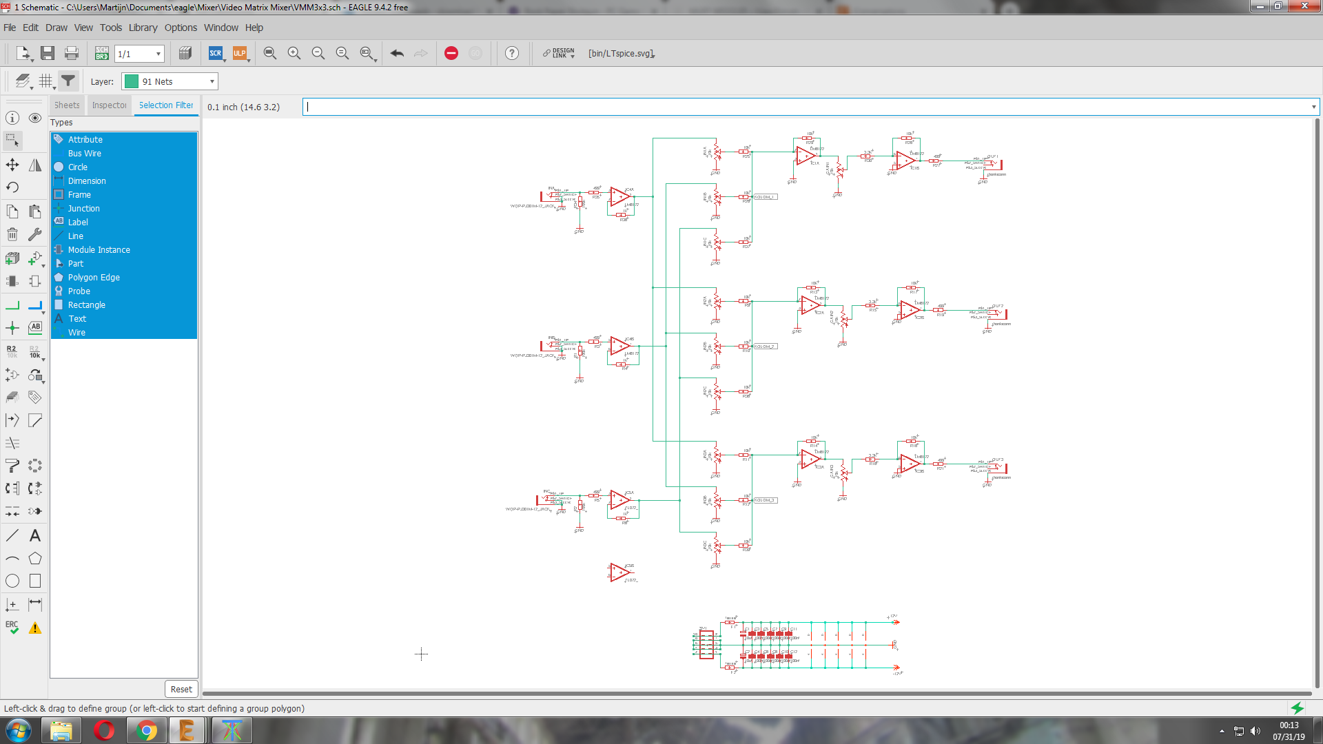
#22 — reverselandfill · 2019-09-24
I decided to keep it like this (no inverted inputs)
I have normalled the inputs together for easy 1 input coloring.
now for the routing…
#23 — wednesdayayay · 2019-09-24
fantastic! looking forward to a unit if prebuilt definitely!
#24 — reverselandfill · 2019-10-21
Routing puzzle:
what would make more sense? (pot layout wise)
option 1 (current layout)
R R R (red)
G G G (blue)
B B B (green)
Zr Zg Zb (gain)
inR, inG, inB - outR, outG, outB -> jacks
or
option 2:
R G B
R G B
R G B
Zr Zg Zb (gain)
inR, inG, inB - outR, outG, outB -> jacks
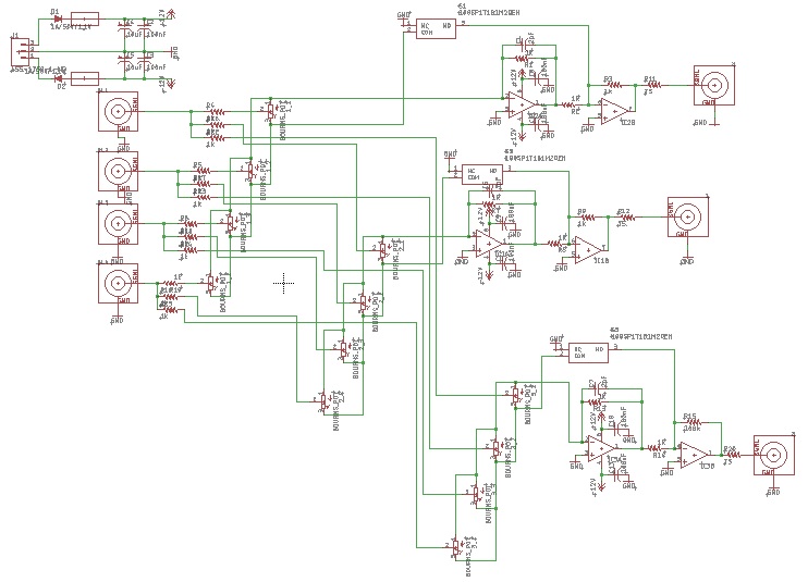
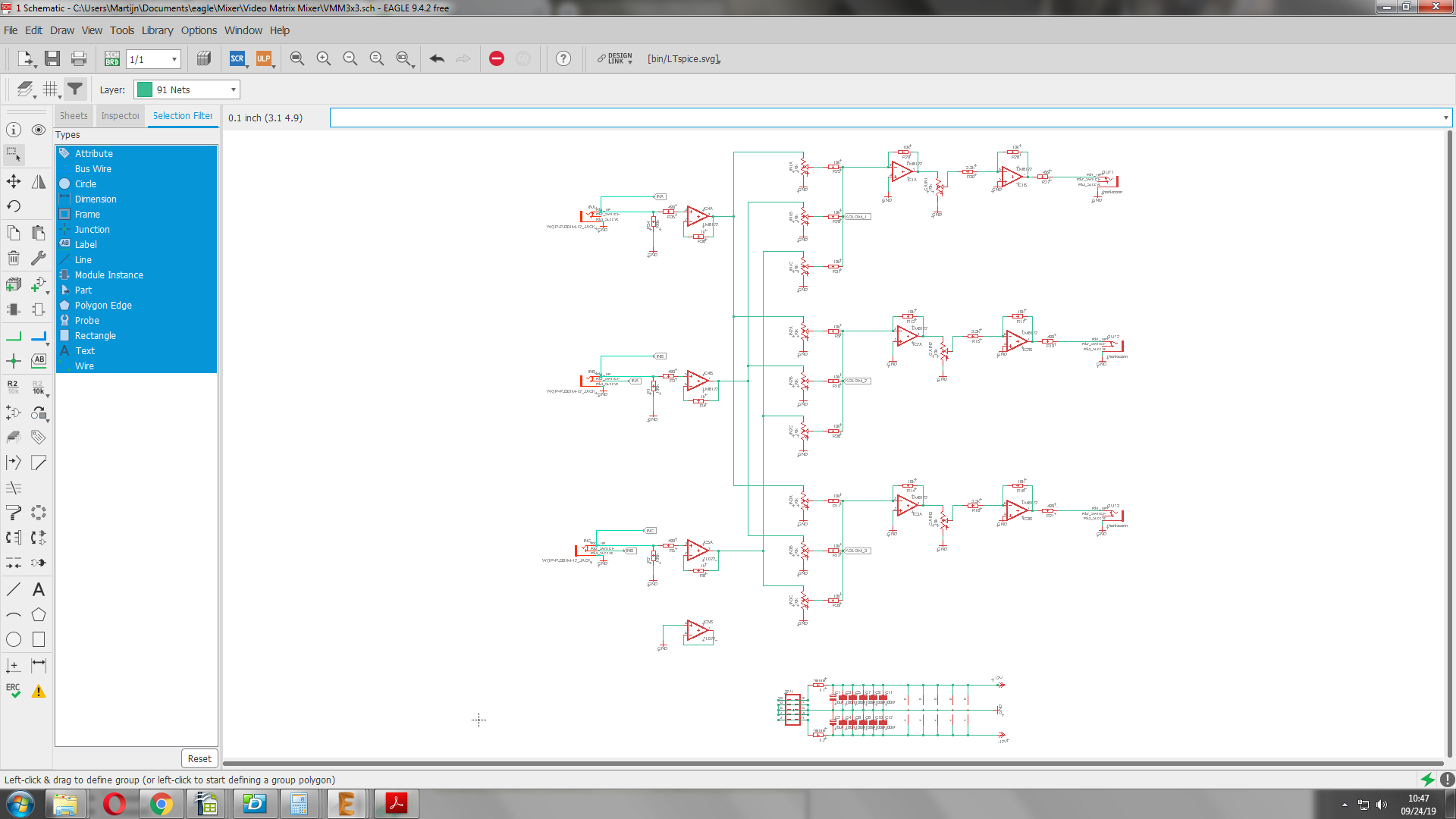
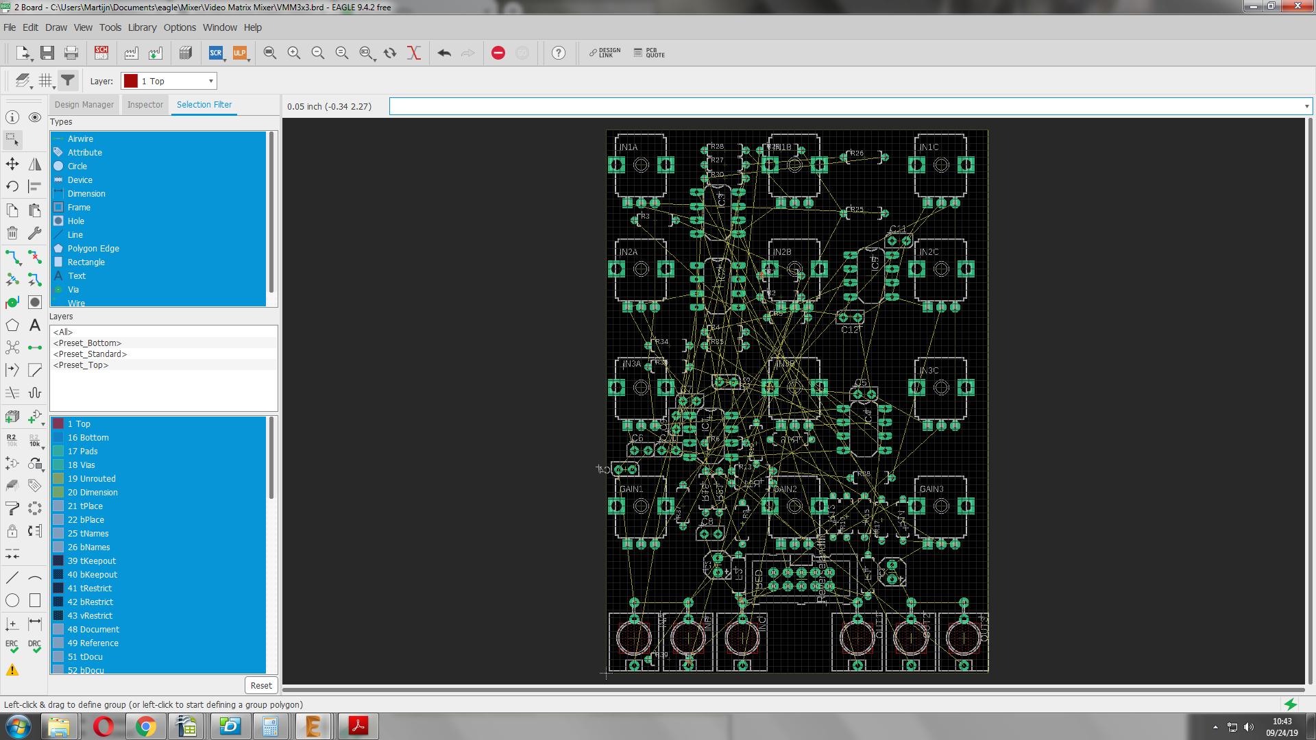
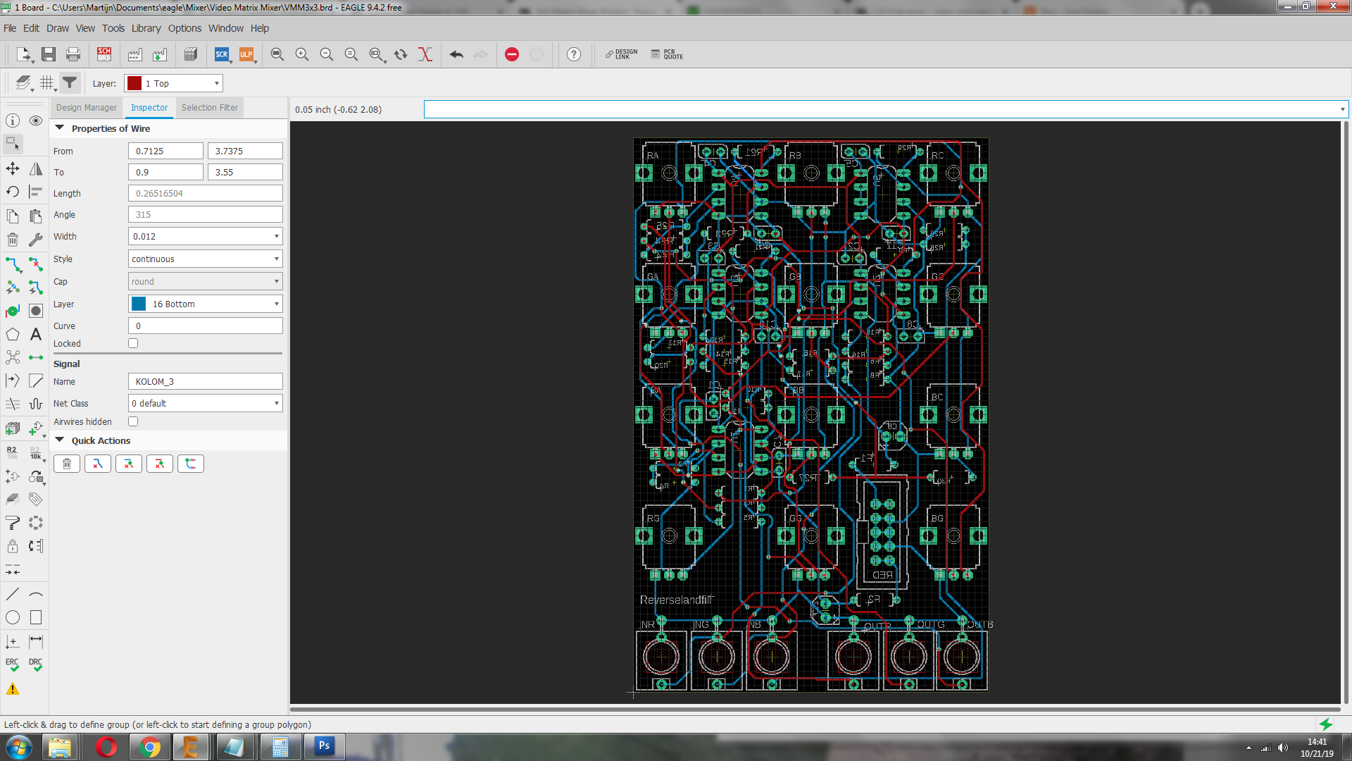
#25 — reverselandfill · 2019-10-21
update routing the pcb
#26 — VanTa · 2019-10-21
To me current layout makes more sense.
The inputs could be connected? In the sense of copying from inR to inG to inG until I plug something into either? ala passage…
#27 — reverselandfill · 2019-10-21
yes. the inputs are normalled.
but then the gain pots are shifted in position.
I try to visualize the paths in my head, but it is hard
#28 — reverselandfill · 2019-10-22
I keep it to option 1. we’ll see how that works out.
next is the panel.
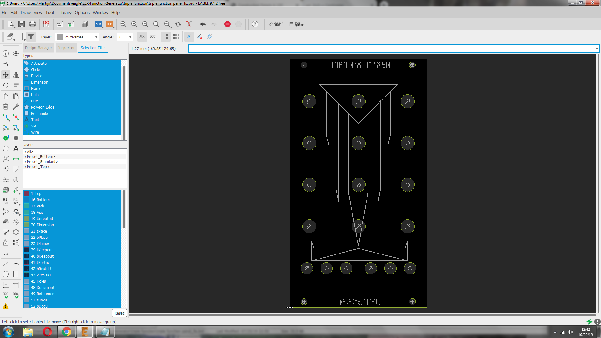
#29 — reverselandfill · 2019-10-22
quick mockup 14HP
I’m going to add some icons for the functions and in/outputs
#30 — trbsnd · 2019-10-24
looks great!
I have finished my 4x3 mixer yesterday, 3 normal inputs and 1 inverted input to 3 outputs.
For me the inverted input is really really usefull, some kind of soft keying is possible, i prefer it over the gain pot per output.
#31 — reverselandfill · 2019-10-24
mmhhh… yeah, I might make something. or a mod option or so
I added the gain pot to do keying as well, with 3x amplification - as Lars hinted at.
#32 — trbsnd · 2019-10-24
maybe you make take a test and decide what you like more… with the inverted input i can make the keying with an cv signal, with the gain it would just be manual or am i wrong?

Or add cv control over the output-gain? 
#33 — reverselandfill · 2019-10-24
how does that work with the inv input and CV?
you put CV in the inv to subtract that amount from the rest of the signal ?
By the way, How did you order the pots?
(see my post above)
#34 — trbsnd · 2019-10-24
if you put for example a triangle wave signal into the invert input it subtracts with a soft border from the mix of the 3 normal inputs. The inv signal goes between the last two lm6172 where your gain pots are located in your schematic. But the signal you put in needs already some softness to softly blend to black. So no control over the keying in the module itself like with a gain pot
My order with in/outs:
in1 R G B
in2 R G B
in3 R G B
INinv Rinv Ginv Binv
outR outG outB
#35 — joem · 2019-10-25
trbsnd wrote:
My order with in/outs:>>>> in1 R G B>>>> in2 R G B>>>> in3 R G B>>>> INinv Rinv Ginv Binv>>>> outR outG outB
I like this arrangement. Makes sense to me. I think I’m favoring the inverted input over the gain pots, too. I’m going to have to breadboard up one of these matrix mixers to try it out myself…
#36 — reverselandfill · 2019-10-28
If I do the inverted option, the panel will be 16HP.
I have the jacks at the bottom now. If I place them at the left side next to the pots, the panel must be even wider.
note: I can add gain pot pads mod points. as for an expander .
#37 — trbsnd · 2019-10-28
sure sure, my panel is 20 hp
i dont have any space problems in my rack atm
#38 — VanTa · 2019-10-28
A passive expander sounds like a fantastic idea. I could even mount it in a 1U panel
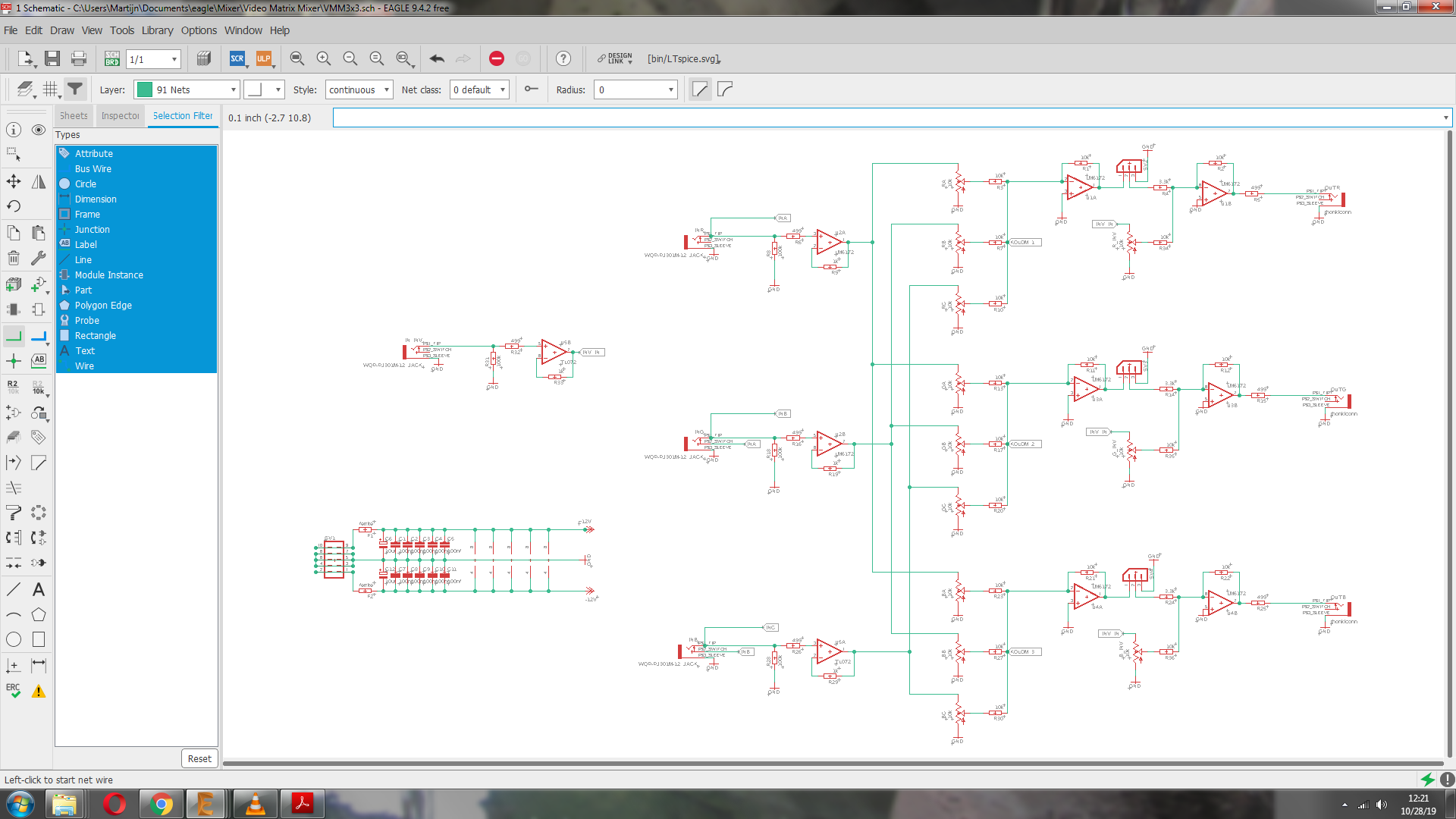
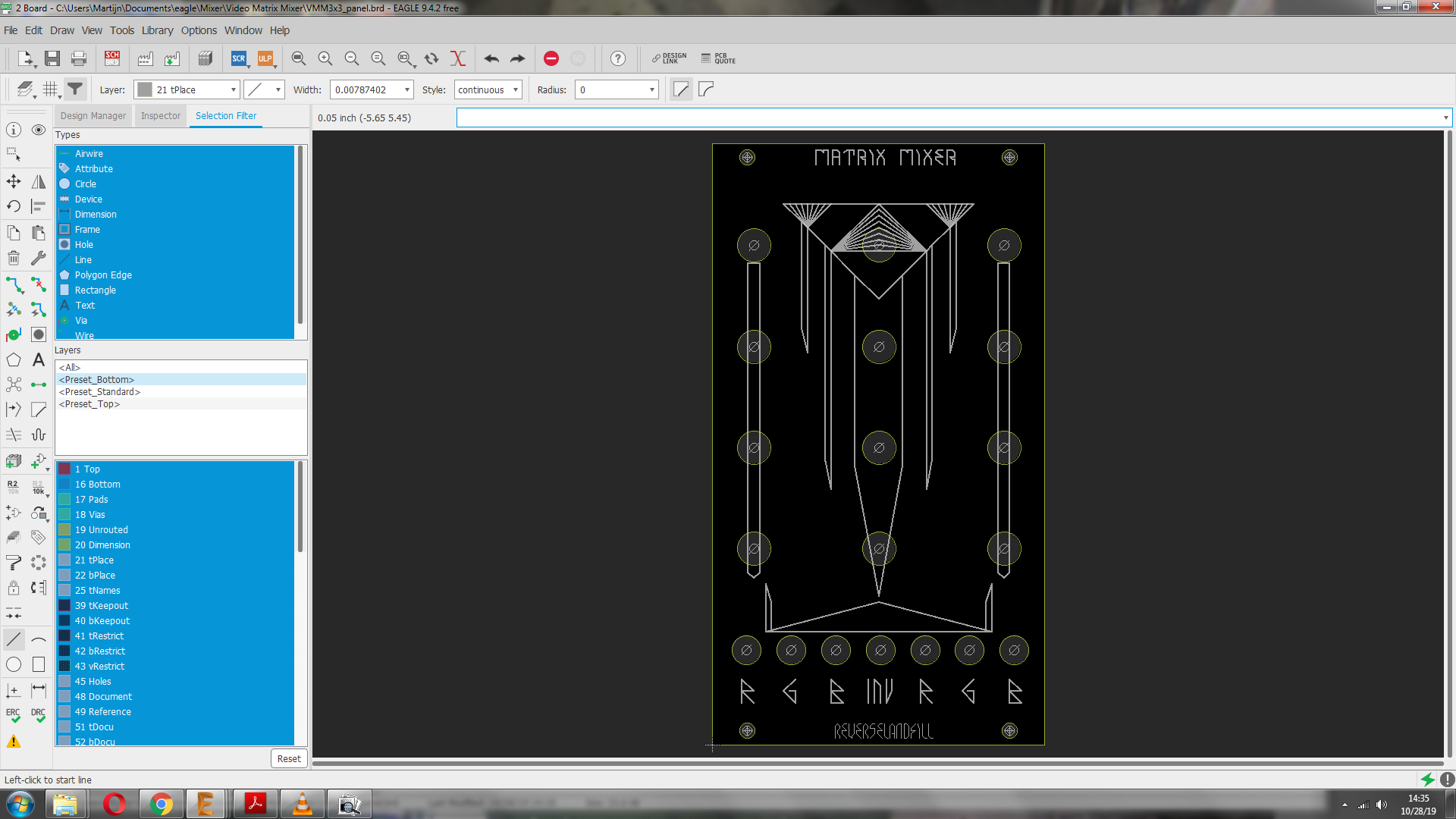
#39 — reverselandfill · 2019-10-28
did you also use 6 LM6172’s ?
current schematic:
mod pins for gain pots, inv input + inv pots added
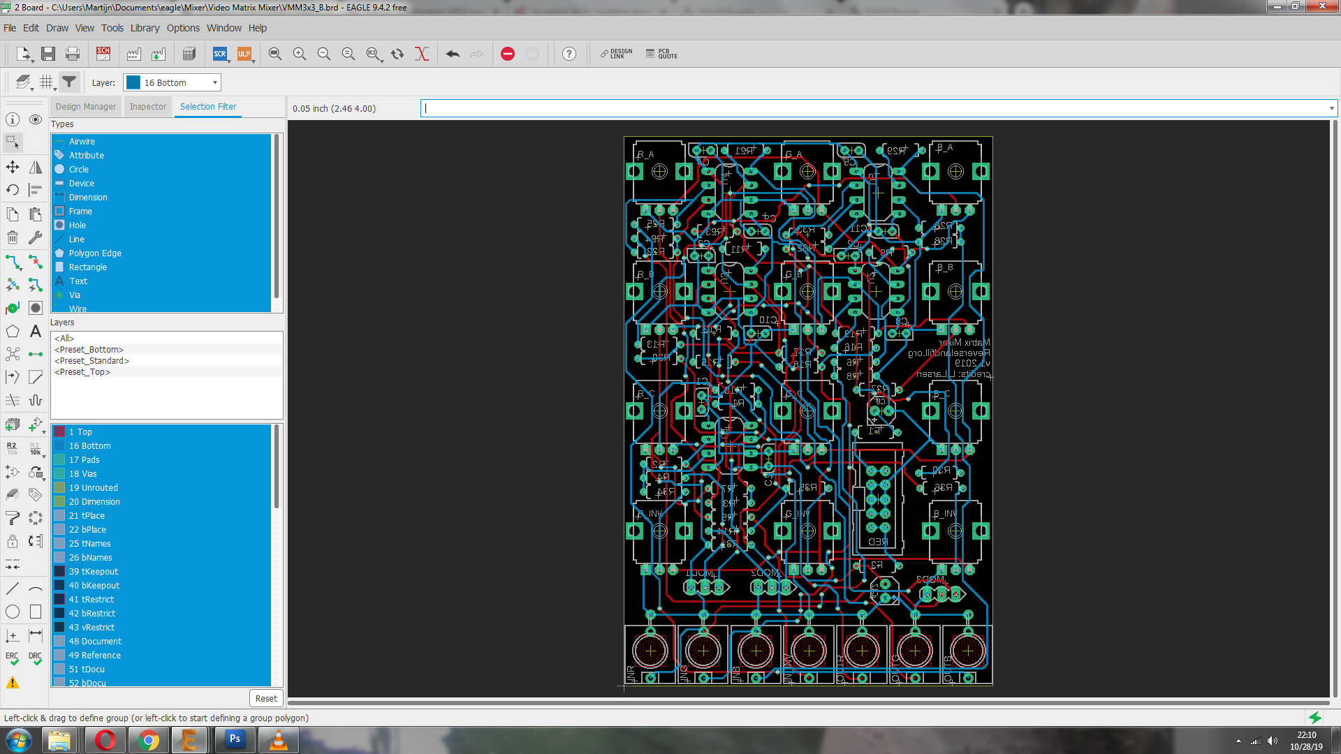
I think it still fits in 14HP
and layout
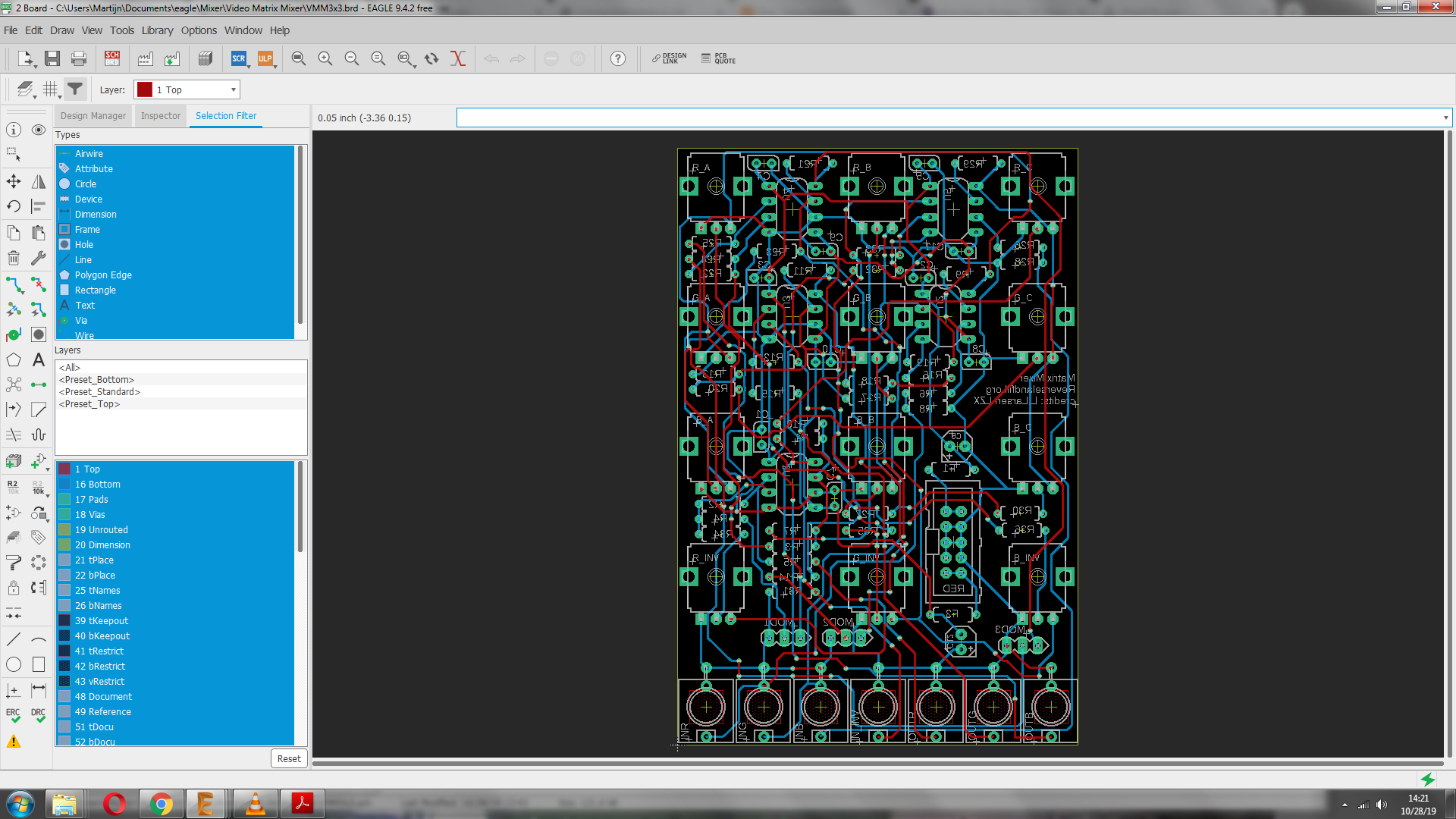
panel
#40 — trbsnd · 2019-10-28
puuh great, still 14 hp! also like the solution with the expander!
yep also 6 lm‘s
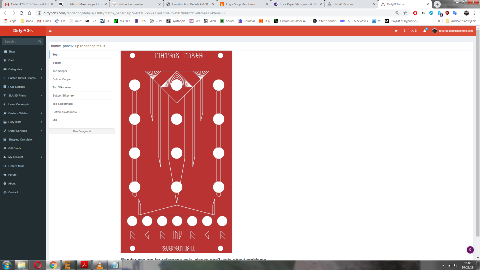
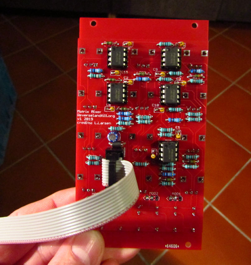
#41 — reverselandfill · 2019-10-28
pcb’s are ordered!
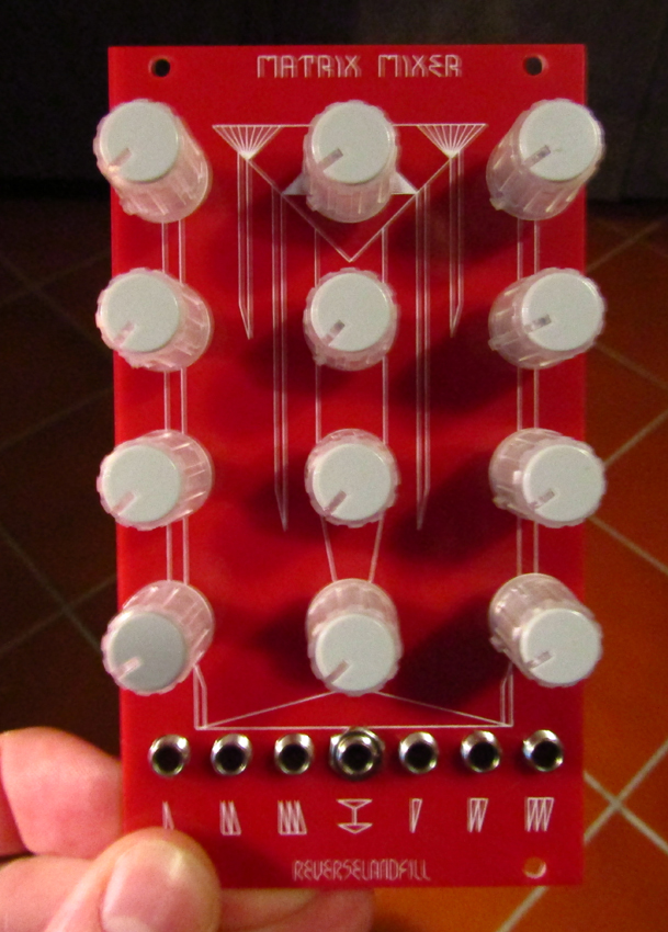
red panel picture:
#42 — reverselandfill · 2019-10-28
lastminute changes:
pot layout is now:
r g b
r g b
r g b
rinv ginv binv
this made more sense.
#43 — VanTa · 2019-10-28
inputs A,B,C, Inv then? or 1 2 3 - , or ChanA, ChanB, ChanC, ChanI …
Somehow RGB as inputs labels is confusing, at least to my ADHD. But I mean, its just labelling, so doesn’t really matter.
#44 — reverselandfill · 2019-10-28
the panel has just drawings, so you have to learn by using it, not read it.
I did add runic fonts for the jack inputs, that will help with patching
I wanted the columns to be of the same channel, so that is the reason I changed it.
This way the INV pots are correctly placed, and one column is one channel so to speak,.
for clarification, I labeled the inputs on the pcb with letters . for input channels R, G, B
so:
R_A…G_A…B_A
R_B…G_B…B_B
R_C…G_C…B_C
R_inv…G_INV…B_inv
jacks: (inputs left, outputs right)
R G B INV R G B
It is confusing to speak of RGB in this context because normally in a matrix mixer you would see numbers not color channels.
This fooled me for a while too, but I think this is the best way (in this 14HP format)
I have an audio matrix mixer (CGS clone by Falafular) which has the input jacks on the side, that makes it very logical and easy to understand.
It is just a design choice, I think the HP space is important for the DIY people, as most Cadet and Castle modules are very small. I do see this module as a performance unit, so some ergonomic space is vital! This is why I chose to have the jacks under the knobs. (and pots with normal knobs instead of trimmers)
as in panel design , would this be better? I changed this in the order already, as I think this makes it more user friendly. No need to be totally symmetrical in the design.
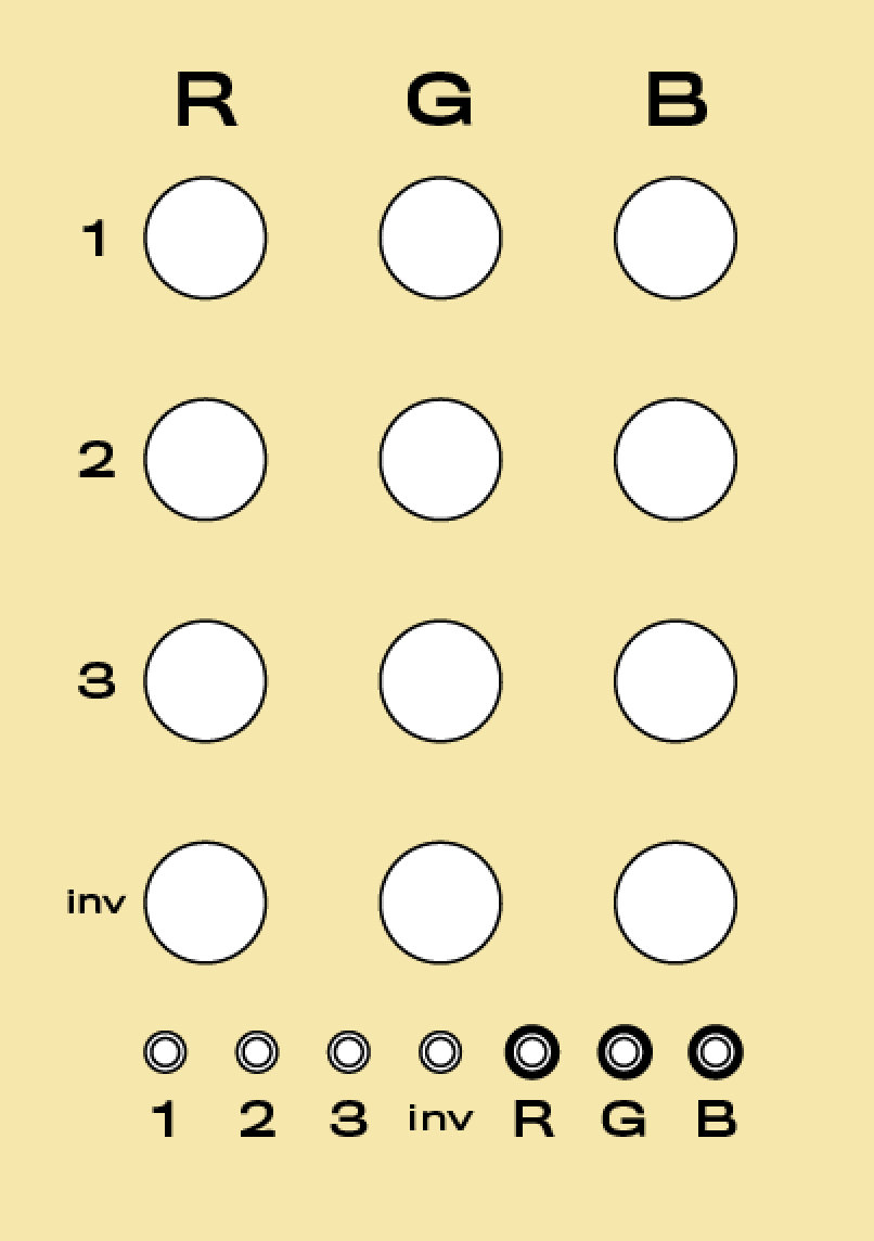
#45 — joem · 2019-10-29
I think it’d be cool if the inputs weren’t named R,G,B, but something more general like 1,2,3 or X,Y,Z or whatever (especially since I’m most interested in using a matrix mixer for colorizing three separate, unrelated inputs). But it’s not a dealbreaker for me, especially if you have the outputs like you have them in that detail pic, with boxes around the label to separate them from the inputs. I really like that. (It really drives me crazy when a module doesn’t have a quickly-discernable indication of what’s an input vs. what’s an output.) And in this case It makes having all the jacks below the knobs much less confusing in general.
#46 — reverselandfill · 2019-10-29
aha. now I get it
it was late yesterday
updated panel
#47 — sean · 2019-10-29
As I think @joem was getting at, shouldn’t input designations be different from the outputs, so it is easier to grok the coordinates of each pot?
So (if I correctly understand how you have it set up) it would be:
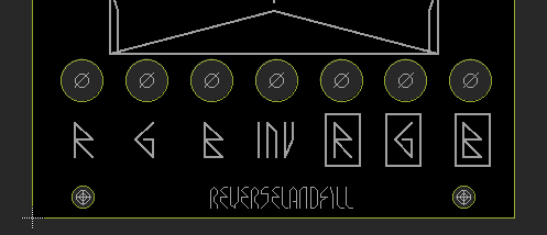
#48 — reverselandfill · 2019-10-29
that is the layout, yes.
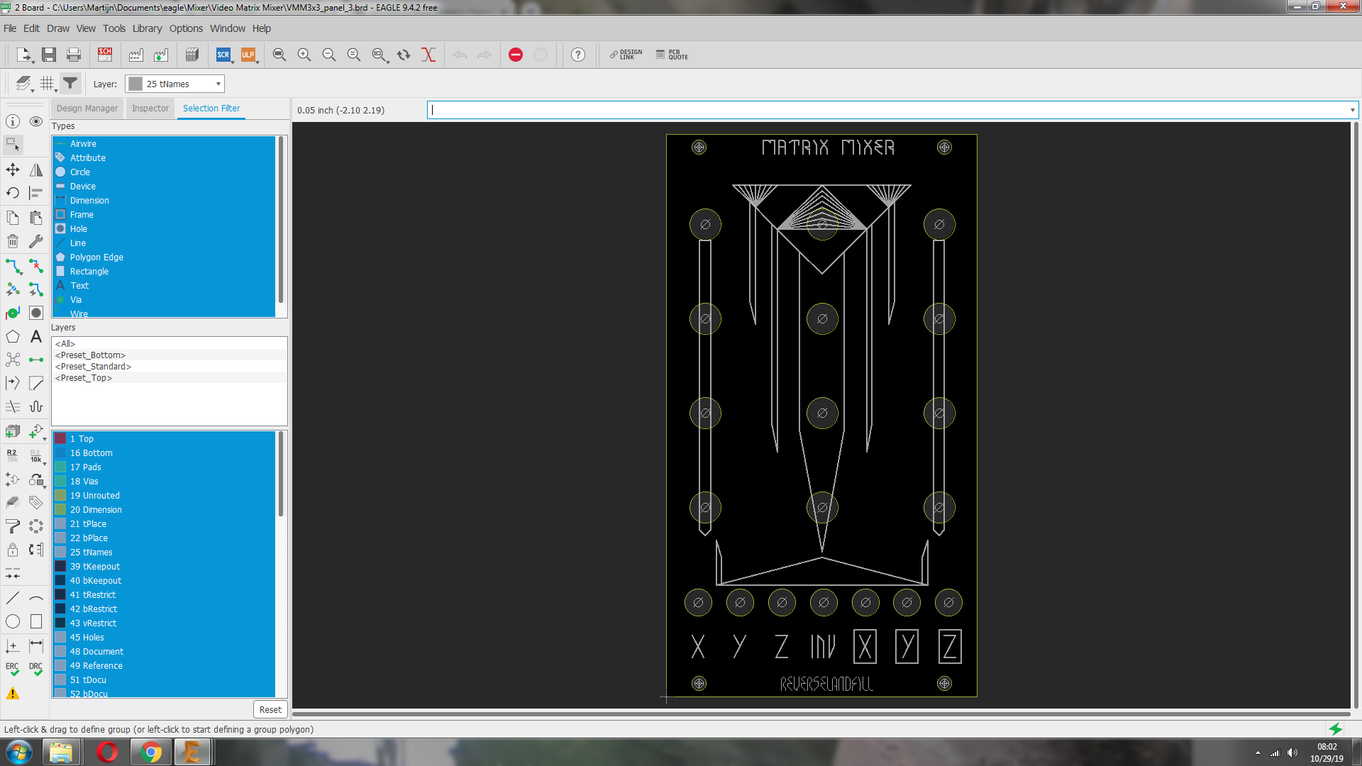
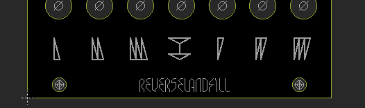
update. I changed it to symbols. (like in all my panel designs)
inputs and outputs are clear this way, and the inv_in is standing out.
#49 — reverselandfill · 2019-11-18
ok the pcb’s are in.
I’ll be building and testing next.
#50 — reverselandfill · 2019-11-18
Building is done, now for the testing!
#51 — reverselandfill · 2019-11-18
aaaaaaaand it tests OK!
instant gratification with color mixing.
I’ll report back later with feedback patching!
whoooo

#52 — LauLindqvist · 2019-11-18
I want it! Can you send me a few boards tomorrow?

#53 — wednesdayayay · 2019-11-18
wow oh wow that looks like it is going to be awfully fun!
I can’t wait to get a built module
#54 — reverselandfill · 2019-11-18
I did some fast feedback patching with 2 loops , 1 direct and 1 with a Differentiator:
there is a lot to play with! just need to wrap my head around the routing
I have build one with 3x amplification, which can lead to fun keying effects
I have to mod the Inverted input to have the same amp stage, so that this can battle against the brightness (just change 3 resistors to 3.3k instead of 10k)
The Bom is done. I’ll make an Order thread.
#55 — reverselandfill · 2019-11-18
the order thread is live.
note: the 3x3 matrix mixer has changed to a 4x3 mixer, with the option to modify it to a sort of 5x3 .
#56 — reverselandfill · 2019-11-18
BOM Matrix Mixer v1 2019:
PCB + Panel v1
Resistors 1% metal film 1/4 watt
10k: r1, r2, r3, r7, r10, r11, r12, r13, r17, r20, r21, r22, r23, r27, r30 (15x)
10k or 3.3k: r4, r14, r24, r34, r35, r36* see below (6x)
499r: r5, r6, r15, r16, r25, r26, r32 (7x)
1k: r9, r19, r29, r33 (4x)
MOD1, MOD2, MOD3 link* see below
Ferrite beads 5mm length
F1, F2
Capacitors
100nf: c1, c2, c3, c4, c5, c7, c8, c9, c10, c11 (10x) ceramic 2.5mm spacing
10uF: c6, c12 (2x) electrolytic 16v
IC
8pin socket: u1, u2, u3, u4, u5 (5x) optional
LM6172: u1, u2, u3, u4, u5 (5x)
Power
10pin shrouder header
10pin to 16pin power cable
Potmeters
b10k 9mm Alpha vertical (12x)
knobs (12x)
Jacks
Thonkiconn (7x)
No MODS:
If you don’t want to do mods, link the pointy side (left) and the middle holes of the MOD headers
If you don’t want 3x amplification, use 10k for r4, r14, r24, r34, r35, r36
The amplification can make it a bit harder to set the gains to precisely 100%, as it goes to 300% in total
Yes MODS:
MOD1, MOD2, MOD3 are header points for the Gain mod.
Solder b10k potmeters here to control the gain for each column. Mount them on a separate panel
The 3k3 resistors can be used as amplification for keying effects
Estimated part costs if you source the parts yourself: 70,- to 80,- euro (without pcb and panel)
This project can also be adapted to an audio matrix mixer. I’ll test this later
This would be cheaper, as you won’t need video opamps.
#57 — trbsnd · 2019-11-19
how do you get these awesome feedback effects?
If i patch direct feedback with mine it just amplifies the signal, cant get trails or other feedbackfx for now…
#58 — reverselandfill · 2019-11-19
I used a Differentiator in the feedback loop
+
a direct loop for extra blurring effects and fadeout or ‘whiteout’
so ch 1 = video input
output 1 = loop1 to ch2
output 2 = loop with differentiator to ch 3
output 3 -> RGB encoder
twist knobs to get all kinds of results!
Note: I do have a 3x amplification on the inputs (see BOM). But I used this feedback routing before. It should also work without that amp stages
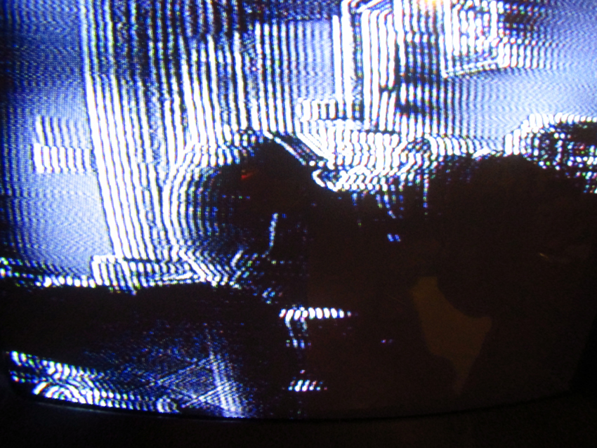
#59 — reverselandfill · 2019-11-19
another feedback patch, with nice keying effects. the inv input now also has 3x amplification
this patch uses camera input on ch 1
and VCO input on the INV channel
feedback on ch 2
output 1 to RGB encoder ‘R’
output 2 to feedback loop
output 3 to RGB encoder ‘G’
luma output is multied to a processor and then to the RGB encoder ‘B’
The 3x amp can key out the horizontal lines to mask the image.
The feedback can streak the lines across the luma input.
The brightness and contrast of the video input help wth the colors, as seen at the end of the video
#60 — Marizu · 2019-11-27
If I wanted to put a switch on each of the MOD pots to switch the pot out and a fixed resistor in, which size resistor should I use to limit the range to 100% (instead of 300%)?
#61 — reverselandfill · 2019-11-27
10k = 100%
3k3 = 300%
I’m not really sure what you mean by ‘switch on each MOD pot’.
The pots control the GAIN of a whole row , so that you can set the ‘brightness’ of a channel of RGB (+inv) if you patch it in such a manner.
#62 — joem · 2019-12-03
Got my PCB and panel and lm6172’s today. Waiting on my pots (which I ordered today) before I put it together. I’m looking forward to this! I’m going to use it mostly for color mixing so I have R, G, and B colored knobs.
#63 — transistorcat · 2019-12-03
Looking at doing a similar mod on my end.
If i understand you, you need to switch in a divider across all three pins (Not just a resistor) equivalent to the pot being set to 1/3, i.e. 6k7 vs. 3k3 with the 3k on the grounded side.
#64 — Marizu · 2019-12-03
Okay. I should be able to use 3PDT switches for this. I’ll take a look at the schematic.
Thanks.
#65 — transistorcat · 2019-12-06
@reverselandfill I may have missed something obvious, but you didn’t release a mechanical drawing for the front panel by any chance? (Even just the front panel gerber drill file would do wonders when putting together my own panel)
#66 — reverselandfill · 2019-12-06
https://www.reverselandfill.org/diy/video-matrix-mixer/
at the bottom of the page are now the panel files. Gerbers and Eagle designs
#67 — Hinotori · 2019-12-16
reverselandfill wrote:
100nf: c1, c2, c3, c4, c5, c7, c8, c9, c10, c11 (10x) ceramic 2.5mm spacing>>>> 10uF: c6, c12 (2x) electrolytic 16v
I received my PCB and board, many thanks!
Just wanted to let you know there is a little error on the BOM i downloaded from your site. It is missing c4 from the 100nf list and lists c4 as the first electrolytic cap. Just wanted to clear that for any other builders.
Thanks for the great project!
#68 — Agawell · 2019-12-16
I already pm’d him about it but well spotted!!
#69 — reverselandfill · 2019-12-17
I have updated the BOM. Thanks for the correction!
Note: It was just a typo, so the kits do not miss these parts. lucky !
#70 — joem · 2020-03-16
I finally built mine today, for color mixing mainly. Works great! Thanks @reverselandfill