VxF vantanalogue RGB crossfader
Category: Unknown · Tags: — · Posts: 42
#1 — VanTa · 2019-12-20
Hi!
Just wanted to share an idea. It’s basically 3xCadet VI faders smashed together with Slider Potentiometers and Normaled inputs. I’d like to be able to crossfade between two 2RGB signals.
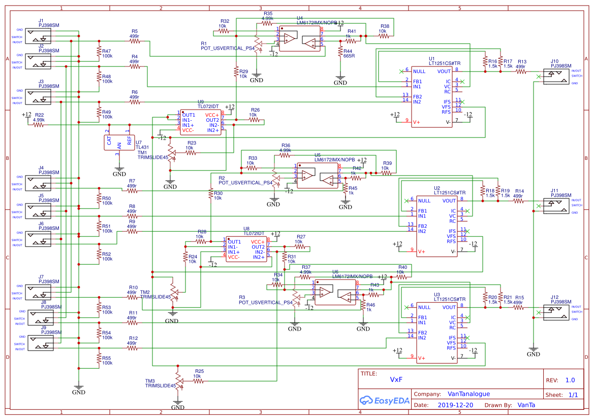
I don’t expect anybody to go through the schematics (it’s the first time I draw one, and its a bit chaotic).
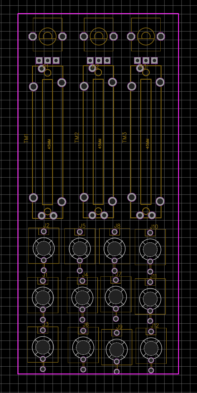
But I would appreciate any tips on sandwiching? It’s probably going to be a 10HP sandwich design with smt components DIY friendly.
I’ll try to order a test pcb over christmas and start the new year with this new exciting project

Wish me luck.
#2 — VanTa · 2019-12-21
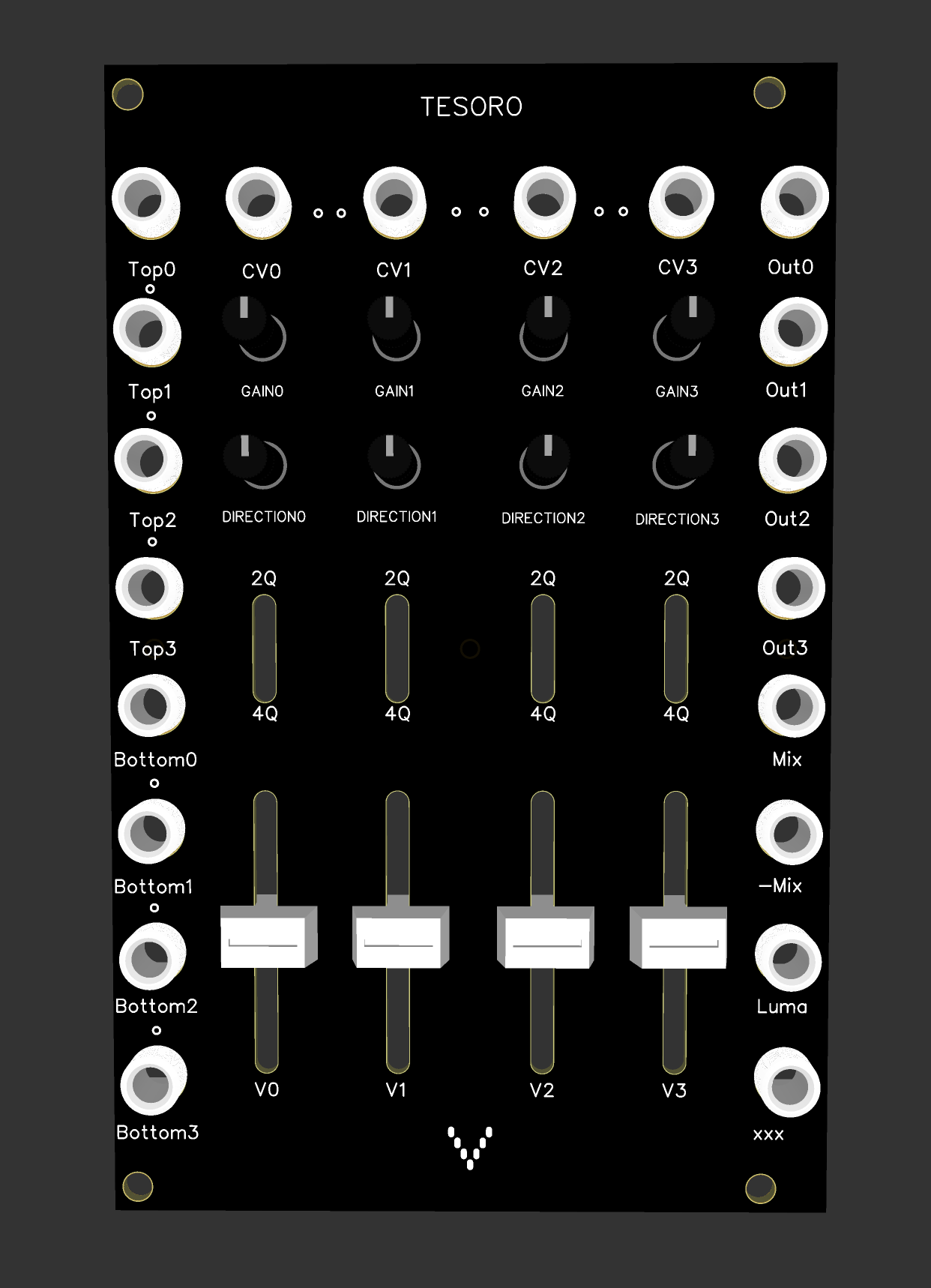
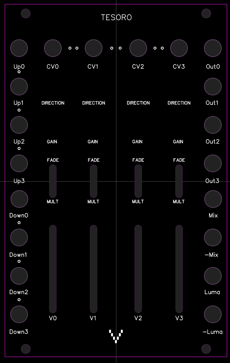
Something like this for the interface:
First three columns of thonkiconns are In-A, xFade, In-B , the last column is out RGB.
#3 — reverselandfill · 2019-12-21
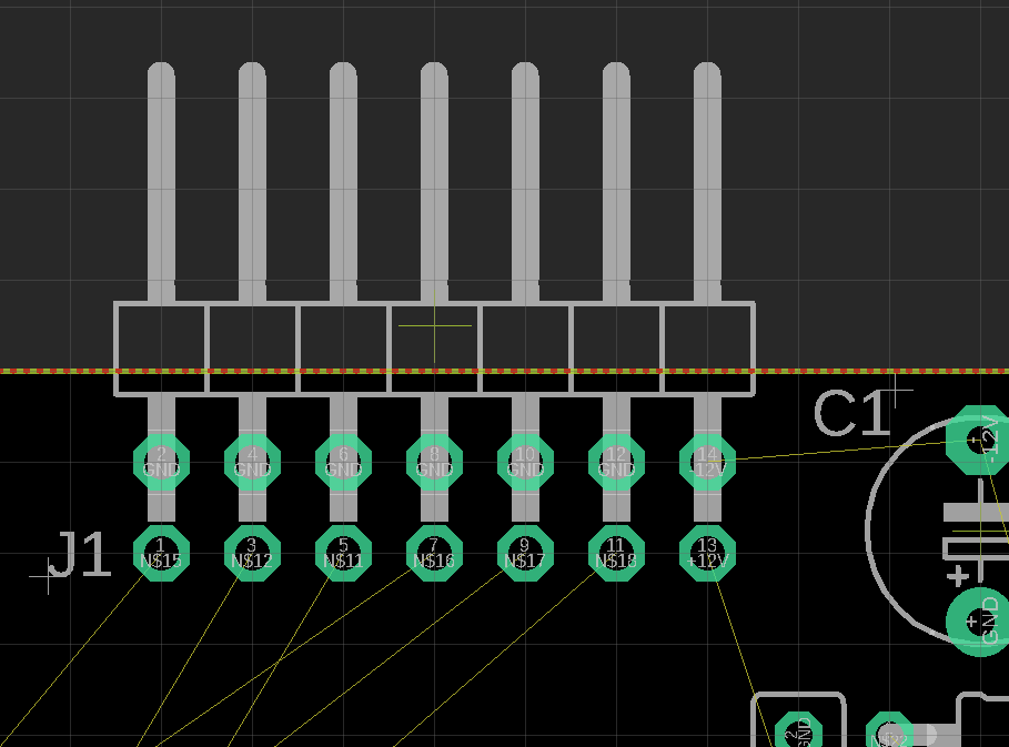
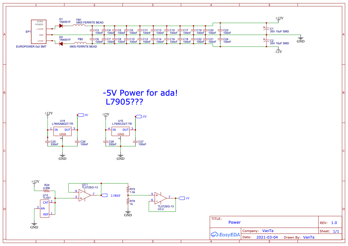
did you add capacitors around the powerheader (10uF electrolythics) and 100nF capacitors next to the IC’s? I don’t see them on the schematic. Look at Cadet schematics for examples on this.
#4 — VanTa · 2019-12-21
True! the power section is not there yet. Thanks!
#5 — luix · 2019-12-22
Nice!! I want one… my recommendation make the INPUT normalizations cascade (similar to Passage) that will be the most flexible o all combinations :), including both A/B inputs and CV. Also dont be afraid of doing it SMD 0805 is big enough and ICs are ez to solder even the inexperienced.
A1 > A2 > A3
B1 > B2 > B3
CV1 > CV2 > CV3
#6 — rempesm · 2019-12-23
I use my current 3x Faders for this task and this layout looks ideal. Agree with normalizing inputs, it makes patching way less messy. Hope you can turn this into a DIY project for the community!
#7 — VanTa · 2019-12-23
Cool, thanks!
Normalized inputs are already in the schematics, I think that part is correct.
Should I buffer the first inputs because of the cascading? Or is it ok like in the original cadet circuit?
The idea of this project is threefold: give back something to the community, enrich the video DIY universe and learn the process of creating a module. That’s why I chose this ‘easy’ design. I have more ideas, but let’s test this one first.
#8 — luix · 2019-12-23
What about adding a flipflop to each fader? So you can switch A<=>B with triggers for animation…
I would LOVE to have a fader with either some flipflops or a simple AD. Thats basically a LZX Pendulum but with triggers input.
#9 — VanTa · 2019-12-23
Thats very interesting.
An analog switch would do the trick, maybe this: https://www.maximintegrated.com/en/products/analog/analog-switches-multiplexers/MAX4760.html
Didn’t really check the bandwidth and other specs, but some chip in that direction.
That will change the layout, though. I didn’t want to go bigger than 8hp…
But if the analog switch is fast enough, it could even work as a threshold.
#10 — Marizu · 2020-01-07
I’d be interested in one of these. It looks really handy.
#11 — northerntao · 2020-01-07
This looks super cool. I would be interested as well if you did a run of them.
#12 — Robbertunist · 2020-09-09
Hey @VanTa

How is your cross fader project coming along? I never read the thread until now but this sounds great. If this worked, could you please share some photos of its visual output & also the finished model & PCB. I’m really curious 
#13 — reverselandfill · 2020-09-09
note on board connectors:
I have done a few experiments with pin headers. For bigger pcb’s: if you use (for example) 2x 1x6 headers on both sides of the ‘main’ pcb and a 2x4 on top / bottom, it makes a firm connection (so you don’t need any standoffs and screws to keep it all in place)
#14 — Robbertunist · 2020-09-10
Ah, now that you’ve written that I realise that I’ve seen standoffs used on bigger modules or on smaller modules where a single one is used because there’s very little header connections.
#15 — VanTa · 2020-09-11
Funny that you say about pin headers, I’m planning to use them but in a funny way, more to come

The project is coming slowly forward, I don’t have much time to put into it sadly. And I’m also not proficient with KiCad yet.
There’s 3 modules on the drawing right now, focused on live performance.
#16 — Fox · 2020-09-11
I have plenty of time to help when I’m at work, but I use Eagle.
#17 — Robbertunist · 2020-09-12
I’m really curious now, headers make perfect jumpers & using them with jumper cables for patching is a great idea when space is absolutely critical. So are you creating a 4x4 or 8x4 header matrix on a front panel?
#18 — VisibleSignals · 2020-09-12
On the subject of cross-fader modules: I will be offering a PCB/panel set for DIY builders soon, which provides three channel (RGB) cross-fader/keyer functionality between two sets of RGB inputs. I’ll write more soon, but if you’re interested or have questions now then please feel free to PM me!
#19 — Marizu · 2020-09-14
Wouldn’t this be better on its own thread?
I’m interested and have a number of questions about it, but I wouldn’t want to confuse anybody that is following the VxF vantalogue RGB crossfader project.
#20 — VisibleSignals · 2020-09-14
Sorry, yes, this was rude of me - I have cut my post back. Sometimes I start typing and get carried away
#21 — VanTa · 2020-09-14
Hi Aladan,
how’s the noise on the ribbon cables working for you?
I tested the same idea and got almost always some noise. At the end I’m going for 90 degree headers, that’s the funny use I was referring to. Sorry Robert, no patch bay

The idea is ‘prepatchability’, so some inputs and/or outputs are already connected in the back of the modules. Plus a matrix mixer can be extended ‘indefinitely’ in the number of inputs.
#22 — VisibleSignals · 2020-09-14
I put a ground on every second pin so it seems to be fine. I can very occasionally see noise in a solid screen of around half brightness (0.5V) of a single colour only, but I believe that’s more a factor of my power supply or maybe even my cadet encoder, because it happens even with other modules.
The only issue that would be nice to fix up is very slight colour bleed/crosstalk if one colour channel is black/0V and the one next to it is a comparatively high voltage (e.g. >5V). But given video voltages are only meaningful in the 0V-1V range it’s usually avoidable by winding back the input attenuator a bit.
I’ve using 90 degree headers too, but the builder is free to do whatever they want and the non-90 degree ones will work just fine. Soldering individual shielded cables would be an option too.
#23 — VanTa · 2021-03-11
I had some time to work on it and its almost there. I’ll order pcbs and test.
The changes have been:
4 instead of 3 ‘vaders’
vaders can be 2quadrant or 4quadrant (mix of cadet fader and cadet multiplier)
Top inputs (top of the vader), normalised to 1v and cascaded
Bottom inputs (bottom of the fader) normalised to ground and cascaded
mix output, inverted mix output and luma of v1, v2 and v3 as output.
Usage scenarios:
- solid color:
connecting outputs 1,2&3 to rgb, you can get a precise color using v1,v2&v3 2. Attenuator x4:
connecting your signal to ‘top’ inputs, you get an attenuated output using the vaders 3. Mixer:
connect your signals to top0 to top3 and mix with the vaders to get the output at mix and inverted at -mix 4. Multiplier x4:
multiply cv and topInput with switch in 4q (then get the mix out) 5. Fader x4:
fade between top and bottom inputs with switch in 2q either with the vaders or with a cv signal (then get the mix or luma out) 6. kind of ‘soft key’ x4
Turn the gain all the way up and the signal at cv will overdrive, making ‘solid shapes’. dirtier then any other solution for this 7. RGB offset:
Connect two rgb sets to top1,2&3 and bottom1,2&3 and fade individual colours with the vaders, or all at the same time (with offsets) thanks to the cascaded inputs.
of course you can mix and match those since they are 4 independent circuits.
the xxx output is to be decided, right now is a XOR between out0 and luma, what do you think?
#24 — VanTa · 2021-03-11
I’ll do another topic for ordering,
but for now, please like this message if you’d consider to get one. It’s just for me to estimate how many pcbs should I order.
#25 — transistorcat · 2021-03-11
What do the “direction” knobs do?
#26 — VanTa · 2021-03-11
Thats what’s called offset in the Cadet Fader: left is -1 of cv, center 0, right +1. Gain will stretch those margins beyond ±1 of the input.
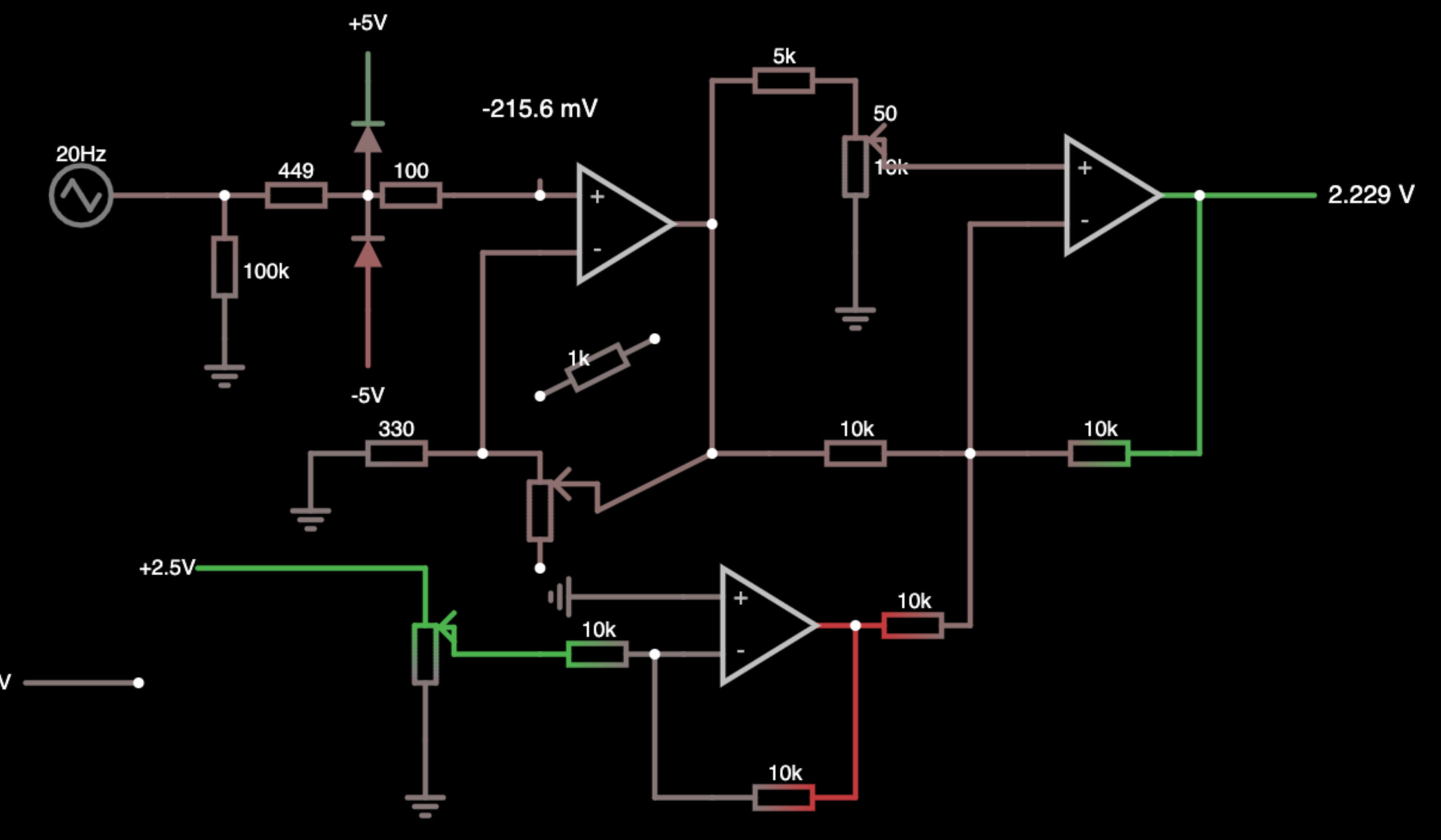
Direction is the pot on the top of the simulation, v is bottom left and gain is in the center next to the 330ohm resistor.
#27 — Analogmonster · 2021-03-11
I would be interested in a pcb/panel combo when they’re ready
#28 — vhsdestroyer · 2021-03-11
This looks super hot. Count me in for one! if you can set me up with a kit or pcb/panel set I’d be stoked!
Side note if you print the panel in the same finish as the Orion/Castle modules I’d be ecstatically happy.
#29 — rempesm · 2021-03-12
What does the Luma output mean? Is it intended to be a weighted mix of RGB like all the LZX modules that use Y to indicate that or is it an arbitrary mix?
#30 — Fox · 2021-03-12
Hey @VanTa let me know if you want a second pair of eyes on the schematic just as a sanity check before you send away for the hard copies. What CAD are you using? I can maybe share my custom DRC file.
#31 — VanTa · 2021-03-12
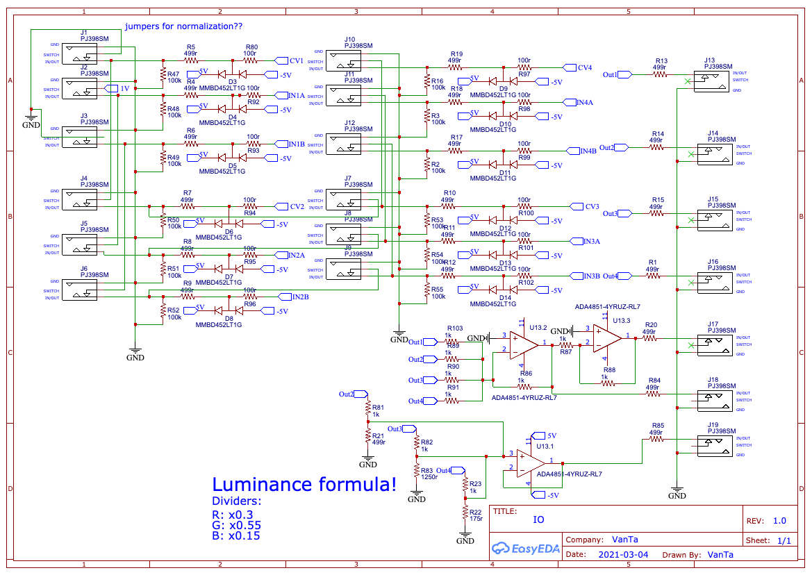
Yes, it is an averaged percepted Luma from the outputs 1-3, not including 0. Similar to Y.
Rx0.3, Gx0.55 and Bx0.15 , its my own approximation and what I use in shaders since a while.
#32 — VanTa · 2021-03-12
Awesome @Fox ! Thats fantastic.
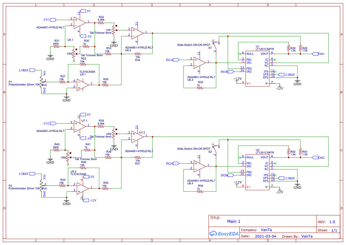
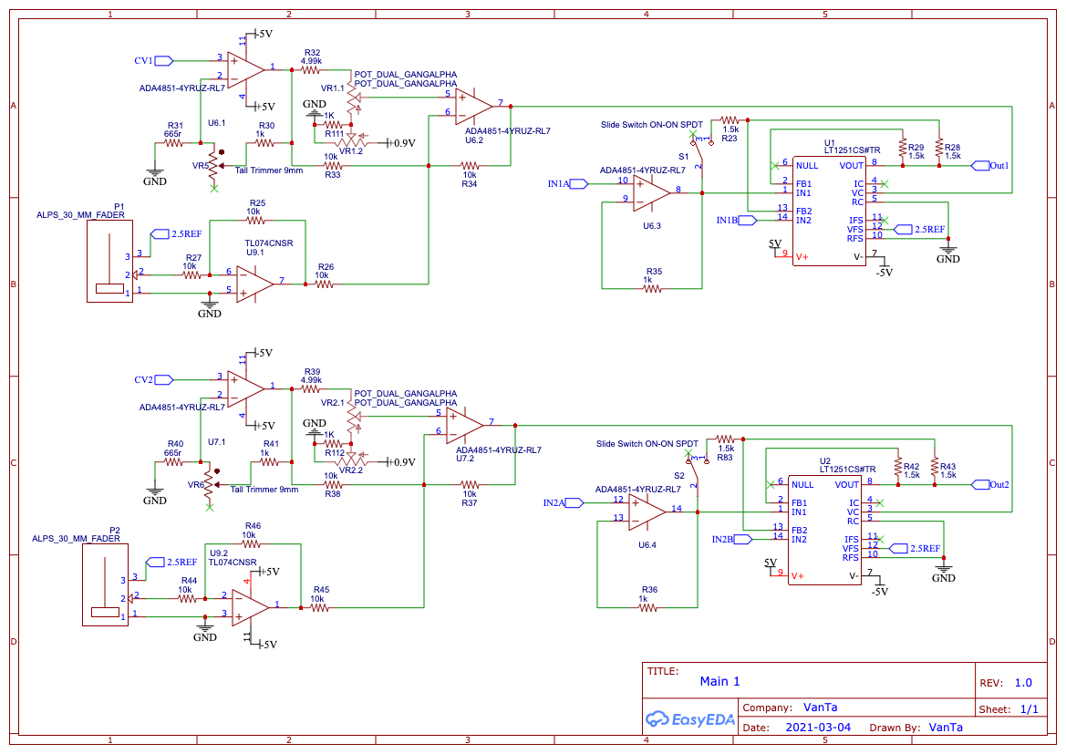
It is of course based on the Cadet Fader, plus a switch to turn it into a Multiplier.
I added a potentiometer in series on the amplifier buffer (min is 2.5x and goes up to ‘don’t know’) VR5 and VR6.
Thats where my main question is. Not sure if that’s ‘correct’.
Here’s the simulation: https://tinyurl.com/yzt2tlwh
#33 — VanTa · 2021-03-12
In the Inputs, I just added protection for the opamps via double diodes, taken from the ‘LZX Interface examples’ by @creatorlars
The mixer and luma section, I did from memory, so probably something is missing there. And the luma resistor values are quite odd… room for improvement.
#34 — VanTa · 2021-03-12
On the power side, nothing fancy.
I think 7805 and 7905 are a correct method to get ±5V, if anybody has a better idea…
For my first electronics project (beyond micro controller based stuff), I’m quite happy.
#35 — Fox · 2021-03-12
I have a few suggestions for you, Vanta, so I’ll just send them over via PM.
#36 — vhsdestroyer · 2021-03-21
any updates vanta? been super stoked about this idea
#37 — VanTa · 2021-03-24
Some updates have been made.
Thanks a lot to @Fox and @Zifor for helping me out figuring out the most basic stuff

The main change is a dual gang pot for the ‘direction’ allowing me to attenuate clockwise and invert+offset cow, although not linear. Expect weird madness there
This also means a ‘exotic’ part to source, for example right now not stocked at thonk. Maybe only kits and no panel+pcb.
Thanks to @Fox the luma output should be correct now and the last output is now an inverted Luma on the 0-1V range.
Here’s the schematics:
If nobody sees a major problem in there, I’m going to route it and order a test pcb.
#39 — Rik_bS · 2021-03-24
Trivial feedback, instead of “top” and “bottom” perhaps just label each channel A and B
So then the inputs would be A0, A1, A2, A3, B0, B1, B2, B3, for smaller neater labels
#40 — Zifor · 2021-03-24
Make sure to get someone to review your placement and traces , in video it is equally important they are done well
#41 — vhsdestroyer · 2021-03-25
I have to agree here as well on this. A/B numerical labels will make more sense.
#42 — VanTa · 2021-03-25
I hear you, originally it was A0-3 and B0-3, then it felt ‘too scientific’ and change it to reflect the fader position, that’s why top and bottom. But i was never convinced either.
What about Up and Down?
I also changed 2Q and 4Q for fade and mult. They illustrate better the ‘what’ instead of the ‘how’.
A graphic designer is helping me with the graphics, although the layout is set.
#43 — VanTa · 2021-03-25
As for the luma question @pbalj
True, its not a dedicated rgb workflow, but it can be used in that way. For example:
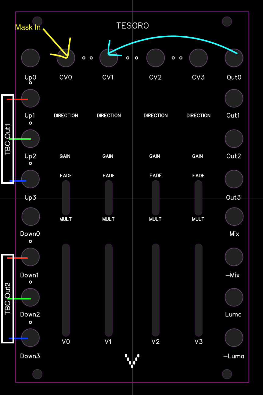
RGB signals coming from example from TBC2 into channels 1 to 3 and use any signal in channel 0 cv as a cheap soft mask to multiply or fade. Then offset the the rgb colours with the v1-3 faders.