Testing Continuity and Bench Power Supply Questions
Category: Unknown · Tags: — · Posts: 7
#1 — simon · 2020-03-07
Hello!
I’m new to both eurorack and diy electronics and have just finished building the first two cadets. Unwisely I didn’t test any continuity until I soldered everything (except for the power headers on the Cadet II) and now when I test with the multimeter I hear a beep when testing for continuity between ground and -12V. I’ve been having a hard time finding a lot of resources online that have been comprehensive for me but if my understanding of what people in these links are saying is right then there should be no beeps between any of the -12V +12V and ground rails on the power header, correct? https://www.muffwiggler.com/forum/viewtopic.php?t=135088 https://www.youtube.com/watch?v=vYwRrVp8B_A
Also I’ve heard people recommend using bench power supplies for testing modules before and am wondering if this is recommended with LZX modules as well and if so which ones people recommend and how they are set up to connect to the 16 pin headers.
#2 — reverselandfill · 2020-03-08
If you get a bleep between -12v and GND, you have a short somewhere.
(and that is not what you want. the module will not work) You need to fix this problem before connecting it to any supply.
The Cadet modules are not that complex, so you should be able to spot it.
Check all solderpads, clean the pcb, check the polarity of the diodes and electrolythic capacitors.
Also check the orientation of the IC’s.
Alternatively, you can post a picture of the top and bottom of the pcb here, and we can help you.
Bench supplies are very stable and have good fuses. But you can also use a random PSU that has a fuse. It help to have a cheap test supply that does not power any other modules. (so you don’t have to worry about breaking those)
#3 — VisibleSignals · 2020-03-08
A quick but important note: you’ll need a dual rail bench supply - with two output voltage rails. Some supplies are confusing because they have both a “+” and “-” terminal, and also a “ground” or “earth” terminal. They provide the selected voltage between + and - terminals, but the ground is unconnected so that you can either connect it to - (to get 0V and +12V) or + (to get -12V and 0V). It doesn’t give you both -12V and +12V rails (even if you select 24V!) This is a common trap for new people so I just wanted to make sure you knew about it

FWIW, I use a small DIY Doepfer euro supply on my workbench, and I’ve inadvertently done some bad things to it and yet it’s still going strong.
#4 — VisibleSignals · 2020-03-08
Also I second reverselandfill’s suggestion to post some good photos of your boards (both sides) so we can see if we can help identify why the 0V and -12V rails are shorted. Solder bridges happen to everyone, but the Cadet boards have been built up by hundreds of other people so the designs are tested good and the likelihood of problems with them is very low indeed. Manufacturing faults are not completely unheard of, but they are incredibly rare and LZX use a good PCB fabrication house!
#5 — simon · 2020-03-08
Thanks everyone for the quick and helpful responses!
I’m gonna take the suggestions of posting pictures of the boards here as my first resort. I should also note that I’m waiting on an order of 99% isopropyl alcohol to clean these (corona-related shortage in my area right now). Let me know if you need clearer pictures of any sections!
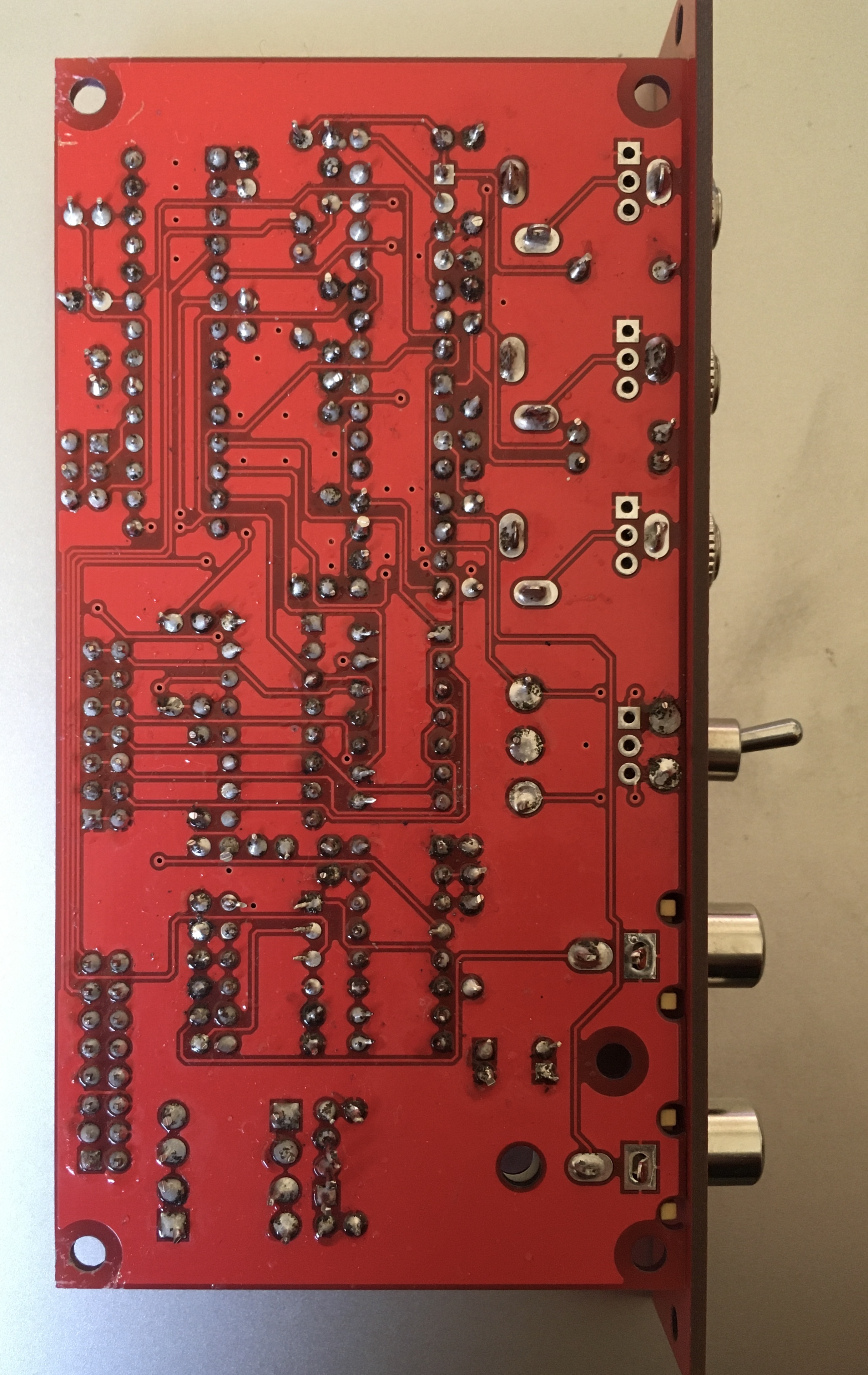
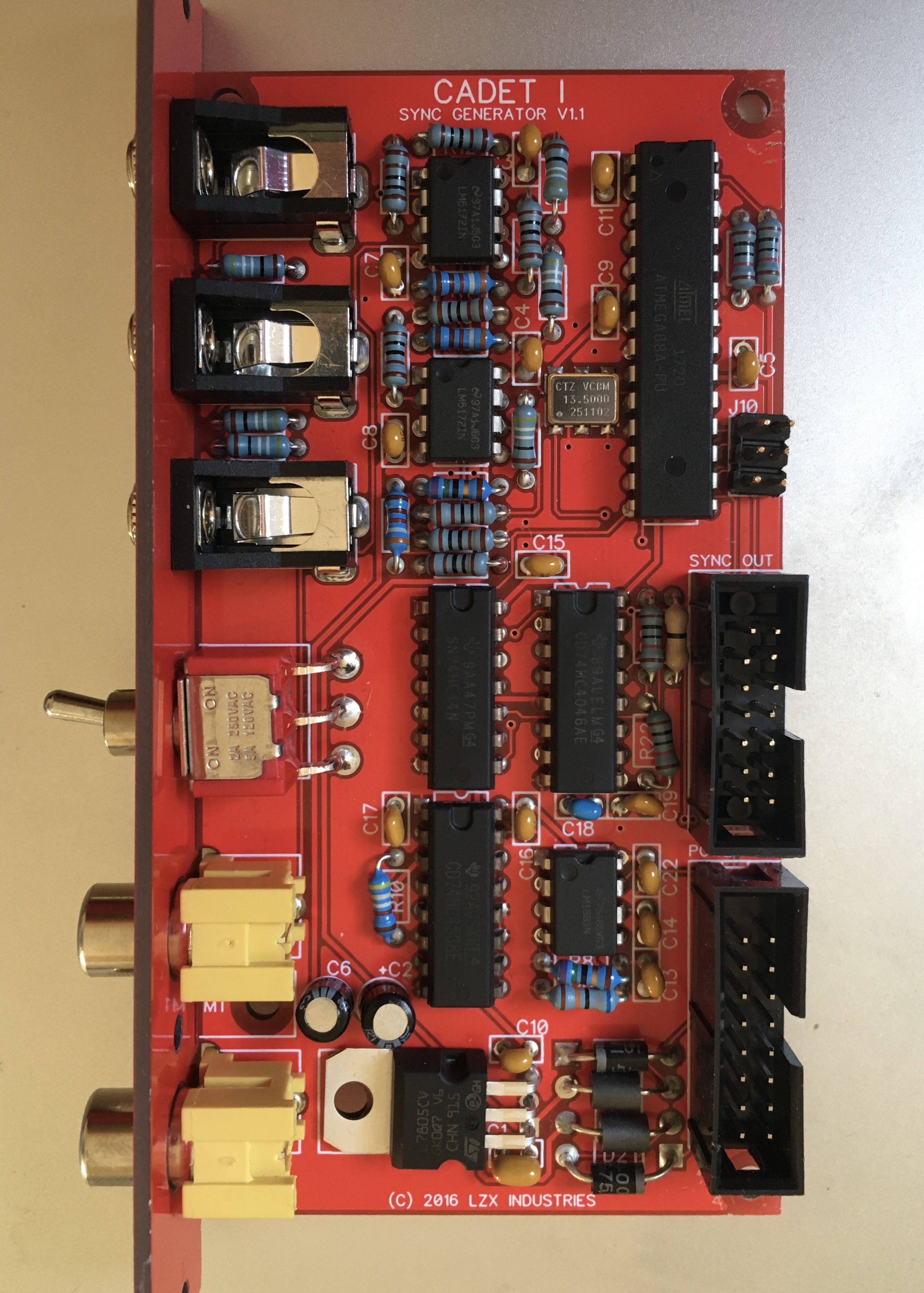
Here’s the Cadet I: I was getting into the hang of soldering with this one and also worry I might have applied too much heat to some of the pads.
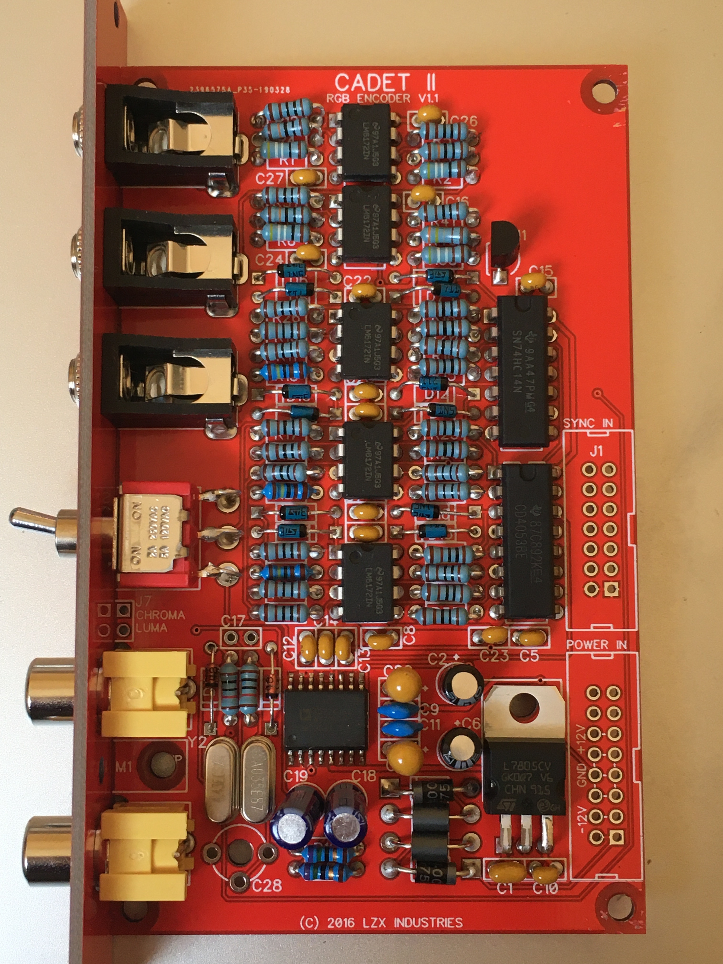
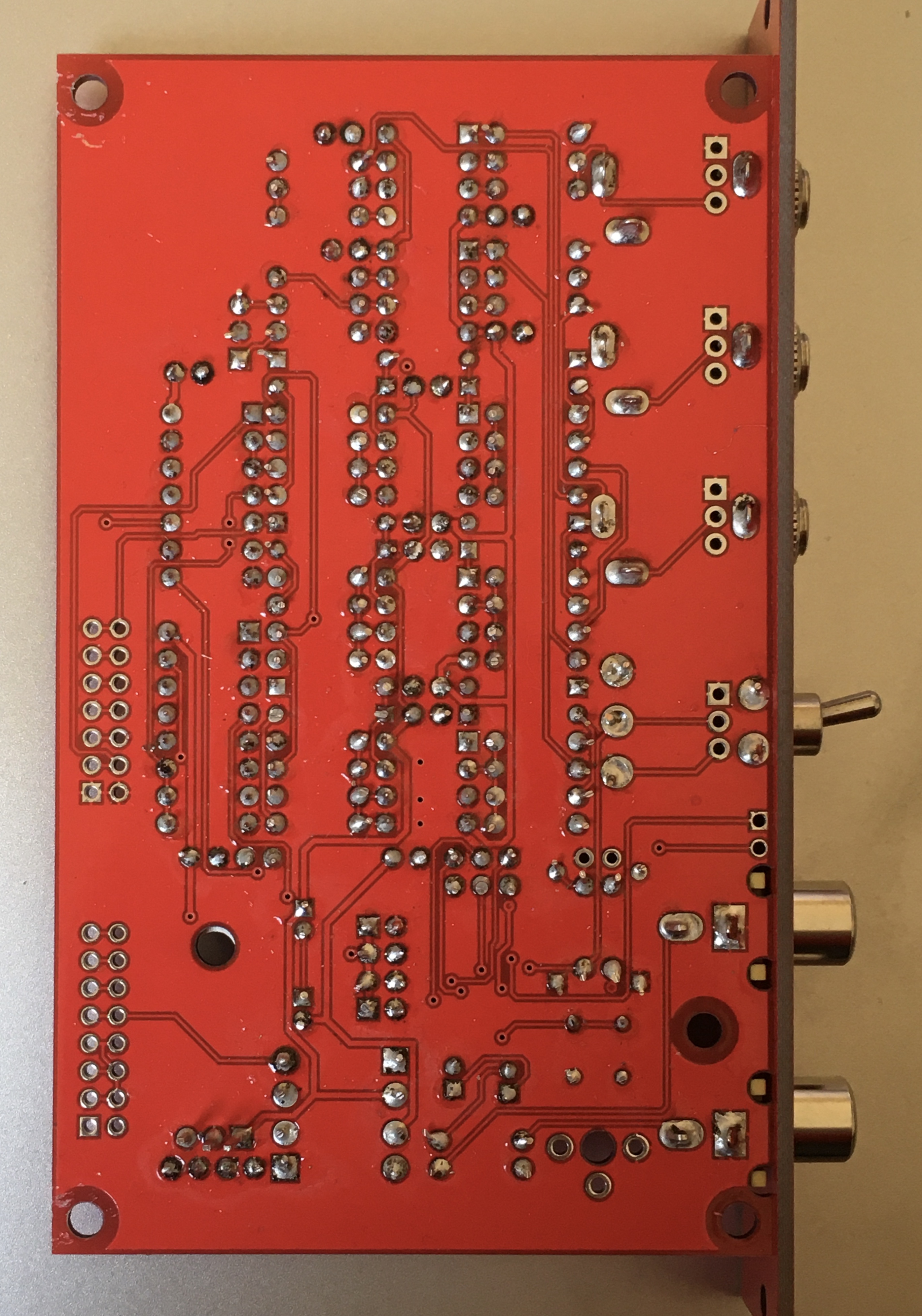
Cadet II:
#6 — VisibleSignals · 2020-03-08
Cadet I: your soldering isn’t too bad! Here is my feedback:
- It looks like some of the component leads could use a bit more trimming - do you have side-cutters suitable for that? I bought these from Thonk recently and they’re good: https://www.thonk.co.uk/shop/side-cutters/
- Due to photo parallax error it looks like the pins on the 5V regulator and C1/C10 might be shorted, and a few other places on the board. Can you please check every solder point closely? I use a magnifying lens with a LED light ring - something like this (but shop around and read the reviews, some are better than others and this Jaycar one isn’t the bestest): https://www.jaycar.com.au/led-illuminated-desktop-magnifier/p/QM3552
- I’m not a fan of the “bend leads over before soldering to hold the components in place” approach (although most people are). Some of your leads appear to bend over so far that they might be shorting against the ground plane if the protective red coating has been scratched off (but it’s probably just photo parallax error again). For example, pin 1 of the 7414 IC. It’s a long shot, but I’d suggest close visual inspection or using a good set of side-cutters (again!) to trim them down to make sure.
- Your solder joints appear to have a fair bit of flux on or in them. I’m no expert there but I prefer to use solder with a little bit less flux, or heat the joint up a bit to get it to burn off. I’ve heard some fluxes are corrosive on component leads in the long term. After you clean it with IPA it’d be worth another inspection.
- Check the power conditioning capacitors on the component side of the board for shorts due to too much solder running through while you were soldering them on. My eyes aren’t the best so I’d use a hand-held magnifier or a microscope like this one: https://www.banggood.com/Mustool-G600-Digital-Portable-1-600X-3_6MP-Microscope-Continuous-Magnifier-with-4_3inch-HD-OLED-Display-p-1119592.html
On to the Cadet II:
- Basically all the same comments as for the Cadet I.
When you say that the rails “buzz” between -12V and ground - what setting do you have your multimeter on? Try using a resistance setting and look at exactly what the resistance actually is. If it’s less than 1K then it’s definitely no good. Next question: are you measuring on the -12V input pin on the power connector, or a -12V pin on component? There is a diode and a ferrite bead between the power connector and the -12V rail going to the components, so knowing where the short is will help narrow down where the problem might be.
#7 — Agawell · 2020-03-09
+1 for what Aladan said
trimming the leads as short as possible (there shouldn’t really be any lead left visible just the cone of the solder, or as near as damn it) and then checking for shorts again seems like the best idea
I don’t like the look of the right side of the IC bottom middle of the cadet1- so I’d look at this area especially
As for bending leads to keep components in place - I find that straightening one lead, soldering and cutting that and then straightening, soldering and cutting the other lead works for me - I usually do batches of a dozen or so
careful with the ipa when you get it - i’m not sure, but I’d try to avoid contact with the panel components if i were you
and as for a bench power supply - I just use a frequency central power supply that is cheap and easy to fix if I manage to kill it - mind you it’s the wall warts that fail first most - and they are more than 10€ each - so better not to draw too much power from them or short them out