DIY Component Output
Category: Unknown · Tags: — · Posts: 49
#1 — rempesm · 2020-03-28
I use Cadet modules for I/O on my system and recently added S-Video output to my Cadet II in place of the PAL/NTSC switch which has worked well.
I’d like to move on up to component output and after researching a bit, I think I’ve found a schematic I could reasonably adapt to add component to Cadet II. I know just enough about electronics to get into trouble so I wanted to ask if anyone had some pointers before I whip up a protoboard.
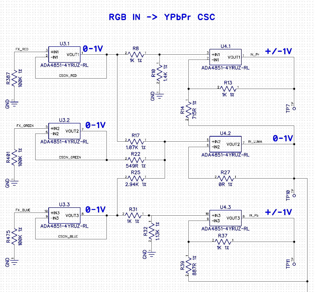
Would I be able to simply tap the Cadet II’s RGB lines that go into pins 6-8 on the AD724 before C12, C13 & C14 and put them into the RGB to YPbPr schematic below starting at the non-inverting input pins of the 3 LM6172s (skipping the input 75 ohm resistors and CD4053 stage)?
For sync insertion onto the Y channel thru Q4, could I tap the CSync pin from the Cadet II’s sync header instead of having the LM1881 in there?
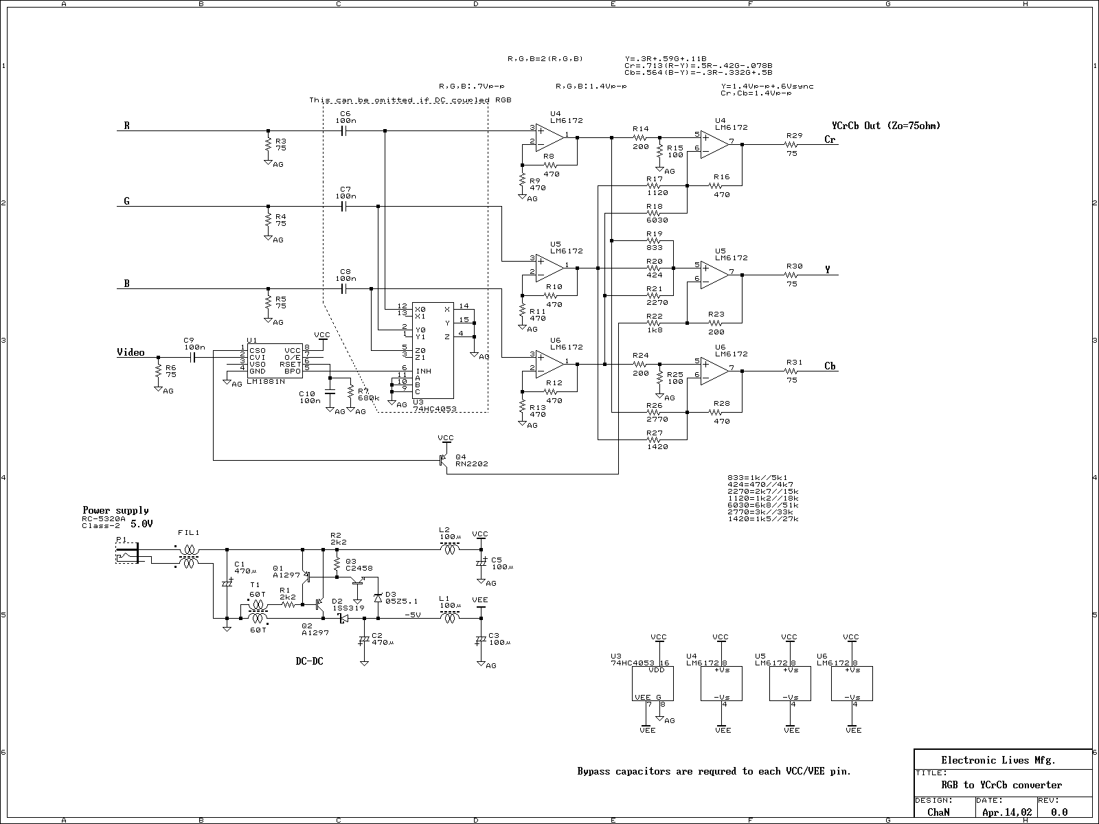
raw.githubusercontent.comhttps://raw.githubusercontent.com/lzxindustries/documentation/master/Cadet%20II%20RGB%20Encoder/Cadet%20II%20RGB%20Encoder%20Schematics.pdfhttps://raw.githubusercontent.com/lzxindustries/documentation/master/Cadet%20II%20RGB%20Encoder/Cadet%20II%20RGB%20Encoder%20Schematics.pdf78.49 KB
Link: Cadet%20II%20RGB%20Encoder%20Schematics.pdf
#2 — joem · 2020-03-29
I’m not 100% certain, but I think what you’re proposing will work (as long as the rgb-to-ypbpr schematic is good). I think it’s definitely worth a try to see how well it works. The only thing I can foresee maybe being an issue is the gain on the leftmost LM6172’s in the rgb-to-ypbpr, but that’s only because I’m not quite sure what level is coming out of the black and white level clippers in the Cadet2. Though based on the input specs in the AD724 datasheet, it seems like it should be the 0.7p-p level mentioned in the rgb-to-ypbpr schematic, so it’s probably exactly right! And even if the gain were a little off, that’d be easy enough to fix by changing the relevant resistors there.
Out of curiosity, are you planning on making a separate LZX-to-YPbPr module out of this? Or is it going to be an expansion to the Cadet2?
#3 — rempesm · 2020-03-29
Wonderful, I’m glad it doesn’t look like I’m completely off base here. I’ll try to solder something up soon to see if it works and share that here.
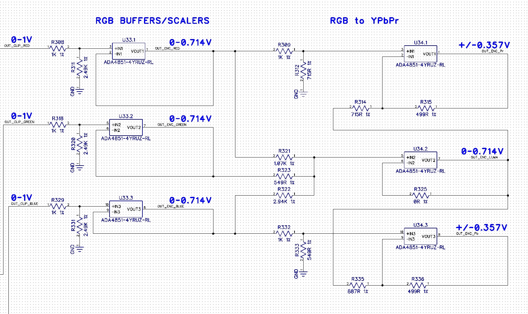
I noticed that they noted the voltage level on the RGB to YPbPr schematic and from Lars’ response on this thread about the Cadet II clipper circuit, it seems to pretty much match up with the expected voltage level.
Hey Aladan! > There are a few ways to do a black/white level clipper circuit. This method, of using two sets of rectifier circuits in series was one we came up with early on. > First off, this type of rectifier circuit (wideband opamp with schottky diodes) is very accurate all the way down to 0V. The point of a precision rectifier circuit is to split the signal into two – negative portions and positive portions. > In the first opamp, the input signal is biased up by CLIPREF and inverted. What th…>
My initial idea was to tack this circuit onto my Cadet II and install the YPbPr jacks in an adjacent 4HP blank or on a 1U row right below it. If this turns out to be right (or if it’s too noisy on protoboard), I’d be up for working with someone who knows PCB layout better than me to produce a 8HP layout with YPbPr built into it.
#4 — VisibleSignals · 2020-03-29
I also think you’re on the right track. Lars’ 0-1V clipper is one of my favourite circuits, it’s so incredibly useful! You will most likely find this works OK on breadboard - I have made lots of circuits like this and they’ve generally worked just fine. The best way to find out the answers to all your questions is to try it out! It’s fun and nothing beats practical learning.
REMEMBER TO DECOUPLE THE OP-AMP POWER SUPPLY PINS

#5 — rempesm · 2020-03-29
Good reminder, thank you! Look forward to sharing what I find out.
#6 — Analogmonster · 2020-04-05
Let me know when you have tested the circuit, I will be up for designing the PCB
#7 — rempesm · 2020-04-05
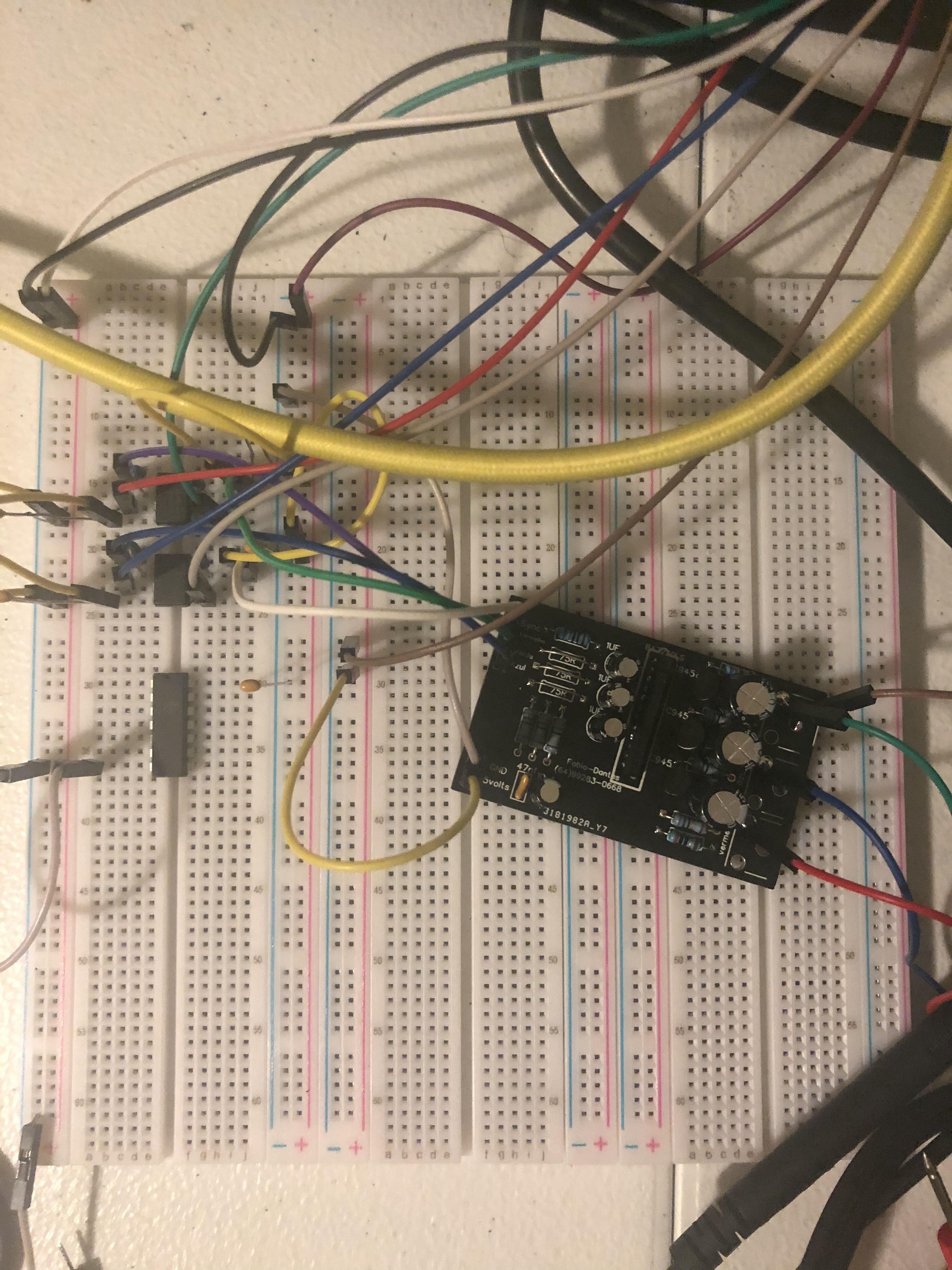
Awesome, appreciate the offer! I got it mostly working on the breadboard yesterday so I anticipate it won’t take too long to iron out the kinks.
Currently all three of the component outputs are sending a valid signal and sync is working but the colors look a little off and there’s a small horizontal smear at the top of the screen. I’m going to throw it onto a stripboard to see if that helps at all and will post an update from there.
#8 — Analogmonster · 2020-04-07
Had a quick study of the cadet II schematic again and a reread of the posts here. Where are you tapping CSync from? Sync signals come into the header and are buffered by inverter U7. If you are taking your RGB from pins 6-8 of AD724, the blanking signal has been inverted twice. You need to take Csync after U7 too otherwise the blanking signal will be slightly behind where it should be. U7.4 output is pin 8. This might be the cause of your issue
#9 — rempesm · 2020-04-07
Ah, that makes more sense–thanks! I went ahead and swapped where I was tapping CSYNC from pin 14 of the sync header over to pin 8 of U7 and that did help clear up most of the horizontal smear I had at the top of the screen.
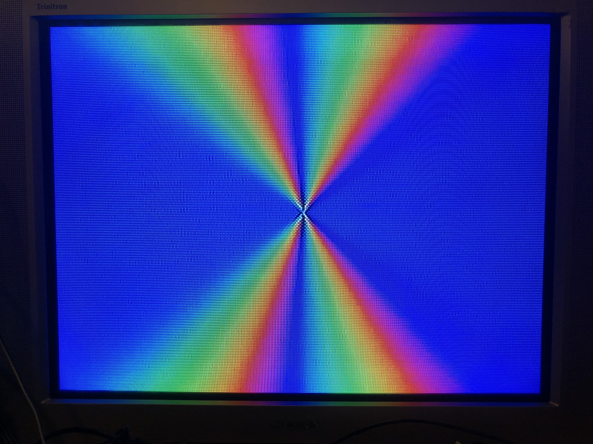
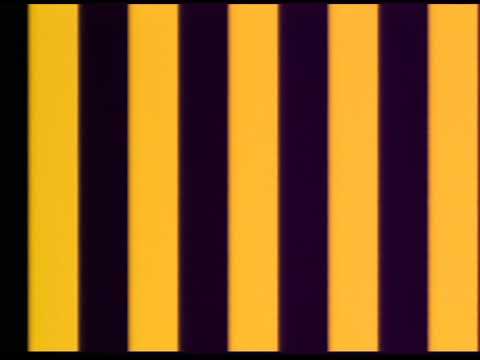
The color is still looking funky, though. Here’s a quick photo from the Cadet II composite output vs. the component output with the same patch. I’m not certain if the wavy lines are the result of breadboard noise or an error with my layout.
I did find another RGB to YUV schematic online but it uses MAX4451s that I don’t have on hand. Not certain if LM6172 is a drop-in replacement for it or requires tweaking.
#10 — Analogmonster · 2020-04-07
I will have more of a think about this, but I think that may be a timing issue also. I zoomed in closely to the second image. There is a pixel that is too bright at regular intervals.
That second circuit, maybe I am blind but where is the sync signal injected?
#11 — gzifcak · 2020-04-07
That photo looks like it’s missing green from the output but its in there somewhere because it’s bright enough to suggest that you’re getting Y. What is your output going to? It’s way easier to just buffer the clipped and blanked RGB lines (and add sync to green if you need), bypass the NTSC encoder and then buffer the outputs if your next input can take RGB. I did this and put a switch to send sync to all three outputs so it could also be used as 3 monochrome outs.
The Cr calculation at the top of the rgb2yuv schematic are at odds with the one at https://en.wikipedia.org/wiki/YCbCr (scroll to ITU-R BT.601 conversion) but it’s not off by enough to do what’s happening in your photo. I built a syncless converter with eurorack input and output impedances using the basic topology from that schematic but doing the math from scratch and it worked well, so I’m guessing it’s a build error, flakey breadboard, or something wrong with the sync insertion into Y.
#12 — VisibleSignals · 2020-04-07
I agree with @gzifcak about the absence of green. The small amount of green smearing could easily be related to that - an unwired input picking up stray signal electromagnetically or similar.
MAX4451 op-amps would be near enough to interchangeable (they are a lower voltage part than the LM6172 though, so the reverse doesn’t apply). I’d experiment with resistor values and/or do your own calcs like gzifcak did.
The curvy dots might be from a switch mode power supply or some other nearby oscillator? Maybe try swapping to a linear supply if you have one, but that’s just a guess, something to check out. Try disconnecting/re-connecting the Cr and Cb inputs to see if you can work out which signal line it is on, that might give you some more info to work with.
#13 — rempesm · 2020-04-19
It’s definitely not quite right on the Y connection.
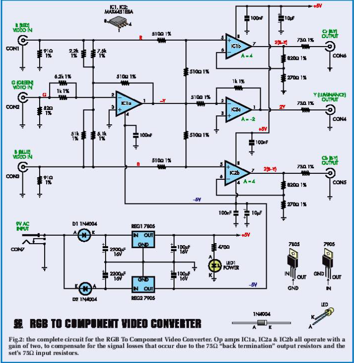
You’re spot on about the second circuit not having sync injected. Here’s a fix I found later:
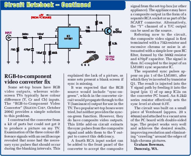
I’d imagine you could just run the sync from pin 8 of Cadet II’s U7 to pin 2 of IC2A in the above schematic.
#14 — Analogmonster · 2020-04-20
I don’t own a display that accepts component in here. Need something for hooking up some old games consoles to the new TV anyway, so I am buying a cheap component to HDMI converter box. This means I can build the same circuit as you at home and help figure this out. I want to make PCBs of these so need to test anyway.
The second circuit has the resistor scaling within margin of error of the ITU-R BT.601 conversion, I would base it off that circuit plus its fix. I am 99% certain you will need Q1 and its 3 resistors between pin 8 of Cadet II’s U7 to pin 2 of IC2A. The fix sums an inverted Y with an inverted sync in an inverting opamp, giving you non-inverted sync+Y. I think without Q1, you will get inverted sync+Y but I haven’t looked at the LZX sync bus with a scope yet. Values of the 3 resistors may need to change.
#15 — Analogmonster · 2020-06-26
Thank you for the poke, I am up for this just not the greatest communicator. I am actually pretty far advanced with this, I have a schematic and a PCB layed out already just haven’t done anything on breadboard yet. I plan for an S-video jack on the PCB too. I might get round to some breadboard experiments in the next day or so.
I spoke a little soon about the resistor scaling. I have calculated correct values. I also think the gain of the 3 amplifiers to the right need to be unity (if I am right then R14, R16, R17, R21, R22 should all be 510r).
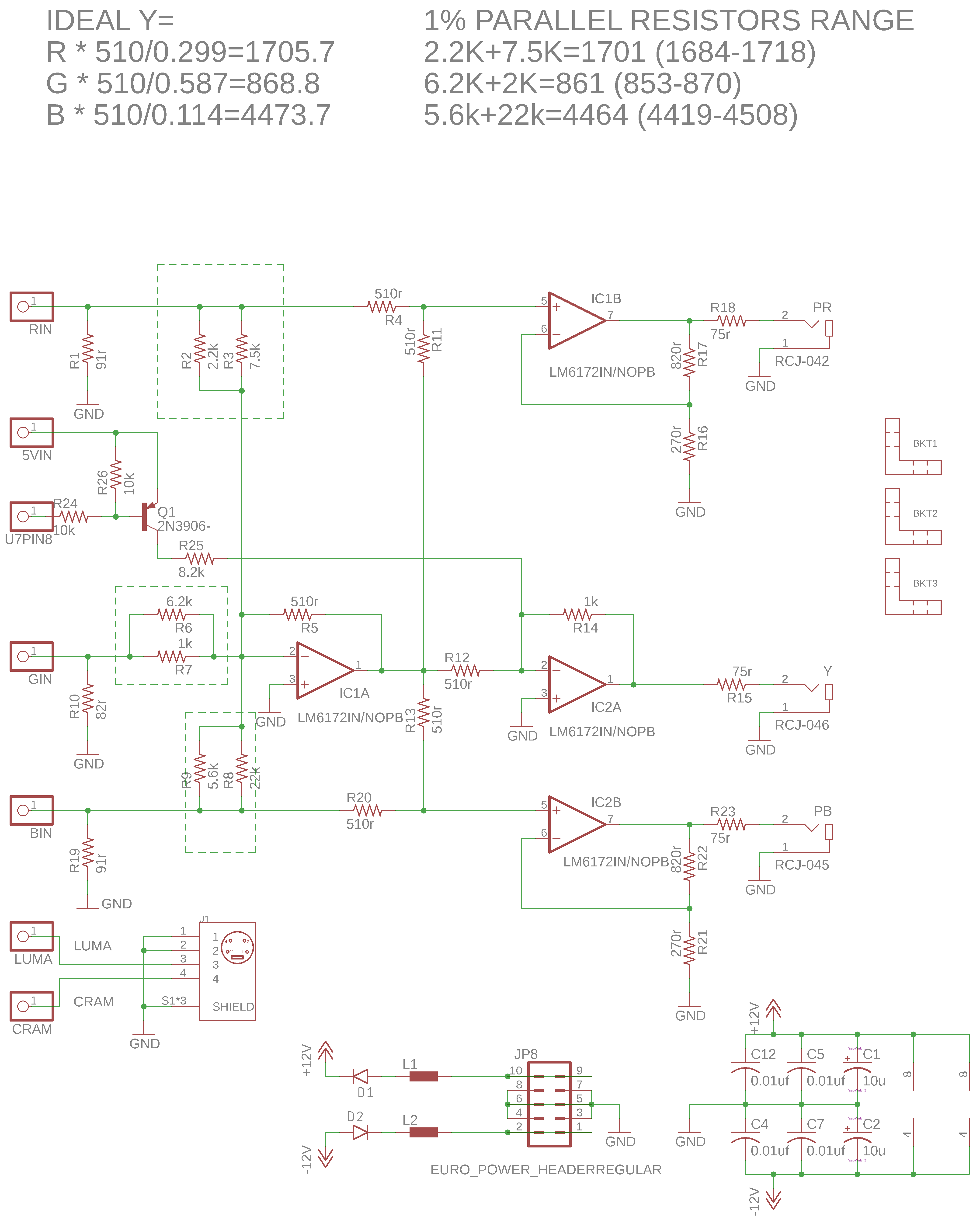
#16 — Analogmonster · 2020-06-26
Oh yeah, also R1, R10 and R19 are just taken from the other schematic and likely not needed here. And if we change the gain of the 3 amplifiers to unity then R25 will probably need to be halved
#17 — reverselandfill · 2020-06-26
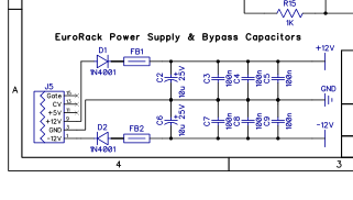
are your 1n4001 diodes reversed?
#18 — Analogmonster · 2020-06-26
It is so hot here today I had to do a sanity check, but no those 1n4001 diodes are pointing in the right direction
#19 — reverselandfill · 2020-06-26
ah wait. this is confusing (it’s hot here too). thats why I normally put the diodes on right side.
like this.
#20 — rempesm · 2020-06-27
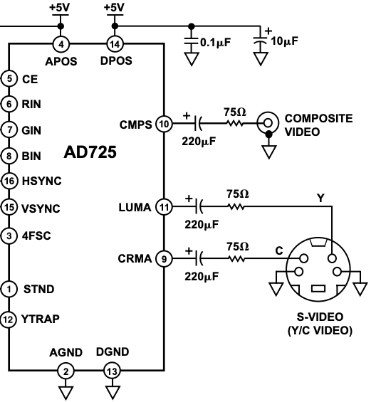
Fantastic progress, thanks for sharing! For the S-Video output, you’ll need to add a 220uF cap and a 75 ohm resistor between the pads and the connector.
From the AD725 datasheet:
I should still have all the parts to breadboard this when they arrive so will post when I try that out.
#21 — rempesm · 2020-06-27
Also, looking at the datasheet, do each of the RGB pins that are tapped before going into the AD725 need to be buffered before going into the rest of the YPbPr circuitry?
“If a separate RGB monitor is also to be used, it is not possible to simply connect it to the R, G and B signals. The monitor provides a termination that would double terminate these signals. The R, G, and B signals should be buffered by three amplifiers with high input impedances. These should be configured for a gain of two, which is normalized by the divide by two termination scheme used for the RGB monitor.”
#22 — Analogmonster · 2020-06-30
reverselandfill wrote:
ah wait. this is confusing (it’s hot here too). thats why I normally put the diodes on right side.>>>> like this.>>
Sorry about that, just poor schematic drawing. Inputs on the left outputs on the right!
#23 — Analogmonster · 2020-06-30
rempesm wrote:
Also, looking at the > datasheet> , do each of the RGB pins that are tapped before going into the AD725 need to be buffered before going into the rest of the YPbPr circuitry?
“If a separate RGB monitor is also to be used, it is not possible to simply connect it to the R, G and B signals. The monitor provides a termination that would double terminate these signals. The R, G, and B signals should be buffered by three amplifiers with high input impedances. These should be configured for a gain of two, which is normalized by the divide by two termination scheme used for the RGB monitor.”
Nice find. I suspect we will be fine here, our op amps are providing the buffering and termination. But the configured for a gain of two part is useful - it tells me the gain of the three ampifiers to the right should remain a gain of 2 as in the schematic. I will add the s-video caps and resistors.
I am knee deep in trying to hand solder SMD LEDs to aluminium PCBs (a complete PITA I do not recommend, even with a microscope and a hotplate to help) but when I have my bench a little clearer I will get the breadboard out
#24 — rempesm · 2020-08-16
Lars shared this in the Video Circuits Facebook group

#25 — Fox · 2020-09-03
I am really interested in Component video too, so I’ll be keeping an eye on this thread.
ANy updates?
Aside, I found these: https://www.mouser.com/datasheet/2/670/rcj_32xxx-1153246.pdf https://www.mouser.com/datasheet/2/393/pjran3x1u__x_series_cd-476138.pdf
The first one is three of the RCJ-04x’s in a custom holder with screw holes, so the extra Keystone mounts would be necessary. I have not looked at the height difference yet.
The second one is a little different than the RJ-04x’s but with an insertion switch. They are also a few mm higher.
Each of these comes in RGB color.
#26 — Fox · 2020-09-06
I found a new schematic that someone has made using a dedicated IC rather than op amps: https://www.sega-16.com/forum/showthread.php?22237-New-RGB-to-Component-converter-design-using-the-BA7230LS&p=699574&viewfull=1#post699574
Problem is, the chip is obsolete and has no replacement. They’re on ebay, but who knows if they are legit.
#27 — rempesm · 2020-09-07
Nice find! I nabbed a few off of eBay that are supposedly NOS but we’ll see when they show up. That IC seems to do a lot of other interesting things I’d like to poke at once I get YPbPr out working.
CSync can be pulled from the sync bus and buffered with inverters like in the Cadet Encoder. 2N3904s will probably be fine to replace the C945 transistors which seem to be obsolete as well.
#28 — rempesm · 2020-09-07
I also found this PCB looking for more info on the BA7230LS which seems to mostly match the schematic from your link. Getting a few boards printed now to try it out.
https://easyeda.com/fabio14789/BA7230LS_componet-0b928d2e6a0d465c9bdb215668e4a447
#29 — Fox · 2020-09-07
rempesm wrote:
Nice find! I nabbed a few off of eBay that are supposedly NOS but we’ll see when they show up. That IC seems to do a lot of other interesting things I’d like to poke at once I get YPbPr out working.
CSync can be pulled from the sync bus and buffered with inverters like in the Cadet Encoder. 2N3904s will probably be fine to replace the C945 transistors which seem to be obsolete as well.
Cool, let us know if the ebay parts work.
The C945 has internal resistors, so while a modern replacement should work, you’l need to bias it with external resistors.
In that same thread, there is a link to an OSHpark project another user uploaded.
#30 — rempesm · 2020-09-13
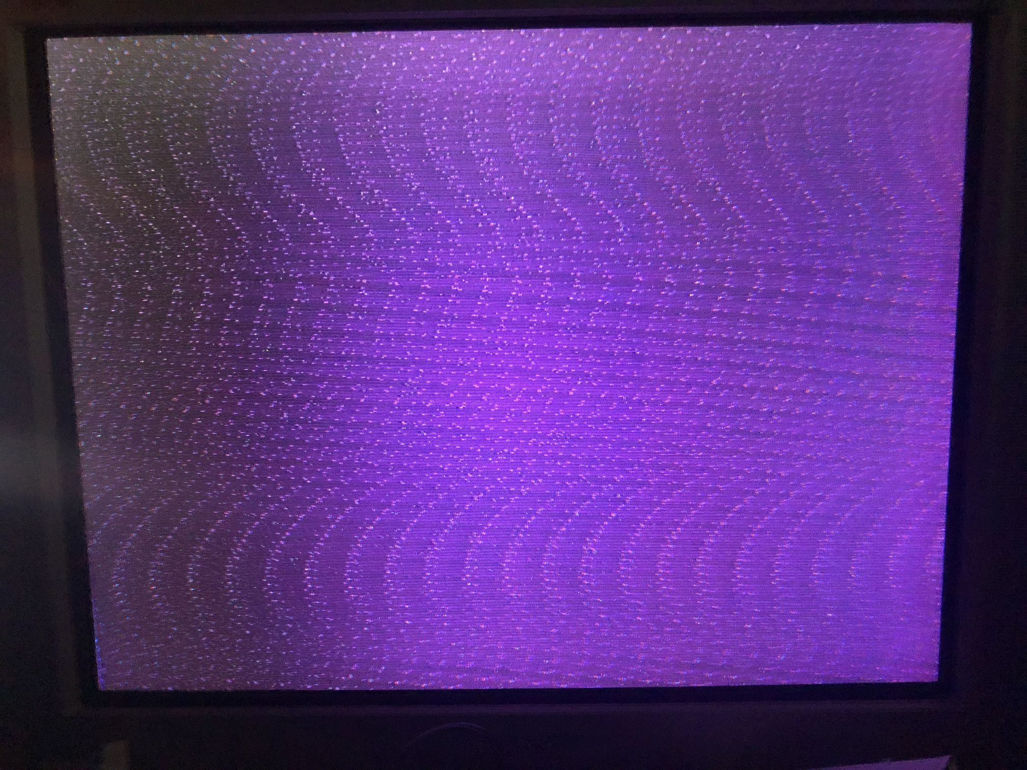
The parts/PCBs showed up today but I couldn’t get anything other than faint purple nonsense on my CRT’s YPbPr input after wiring it up. I ended up getting some BA7230LS ICs and C945s from UT Source which looked legit to me.
RGB, Sync from U7.4, +5V, +/-12V, and GND are being pulled off of the Cadet II.
I found another thread that ran with this design a bit further which ditches the transistors for a THS7374. Also seems to handle sync in a different way as well.


https://www.aussiearcade.com/forum/arcade/arcade-technical-and-repair-questions/monitor-and-chassis-repair-help/99015-pc-rgb-to-component-converter-tv-hack/page5Dead monitor? something dosent look right on the screen? monitor repair questions here.
Link: [PC RGB to component converter & TV hack -
    Aussie Arcade](PC RGB to component converter & TV hack -

    Aussie Arcade)
Github with gerbers is here: https://github.com/dekkit/RGB-to-Component-Transcoder
I ordered some boards and will report back when they come in.
#31 — Fox · 2020-09-13
Can you take a picture of the
rempesm wrote:
faint purple nonsense
And do you have an oscope?
#32 — rempesm · 2020-09-14
I was taking a bunch of scope shots to reply to this and realized partway through that the PCB has the C945 transistor pinout wrong. I also wasn’t getting anything on pin 17 (B-Y) and 18 (R-Y) of the BA7230LS but pin 16 (Y) was putting out something so it didn’t seem like the IC was completely faulty.
I replaced the C945s with the leads swapped and that did it! Full color YPbPr output but with some unstable jitter sweeping through a PR’s full range. Looking at the sync implementation in the Aussie Arcade link (Sync injected right at the Y jack thru a 1.2k resistor), I just ran the output of Cadet Encoder’s U7.4 with a 499r resistor directly into the tip of the Y jack and the frame became completely stable.
I just happened to have a 499r resistor handy and I really have no idea about the correct calculations here. Using a lower value resistance just blew the frame out (full white) and higher resistances seemed to ruin sync. Can anyone point me in the direction of the magical resistor values I should use here?
Here’s a clip fading in the RGB channels on CC with vertical bars from PR. YPbPr output from BA7230LS → Intensity Shuttle TB:
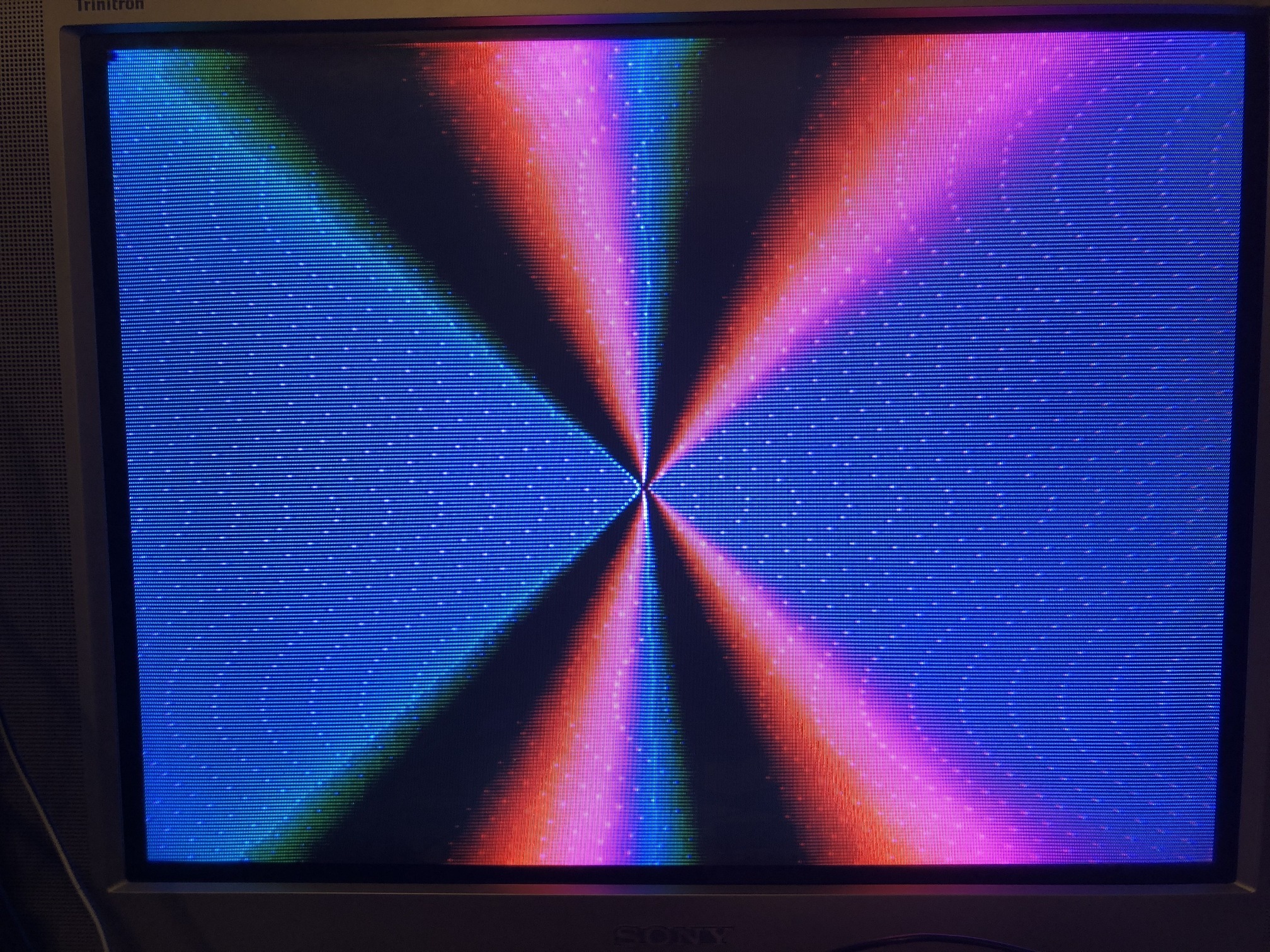
https://www.youtube.com/watch?v=iUj-2ooROKcOn my CRT I can see obvious purple scrolling noise (overexposed example below) whenever my output is black and the capture card seems a bit purply with some random infrequent frame drops, too. I’m guessing I have the sync insertion resistor or mixing wrong.
I have the other PCBs I posted about on the way so I’ll just build one of those up next to try. It’s at least one less obsolete part and the evidence of success seems higher on that PCB than in the other threads. Thought this was promising to see the IC actually works and apart from the purple jitter lines / sync issue, looks pretty good so far!
#33 — Fox · 2020-09-14
A great start! Looks like you’re getting to your goal fast.
The purple is very interesting. What makes purple? Is it safe to assume there could be a tiny positive voltage offset on two or three of the outputs which causes black to appear purple?
#34 — rempesm · 2020-09-14
It makes sense that an offset on both Pb or Pr could cause purple but the effect seemed not as apparent when I removed Sync from Y. I don’t know how that would affect Pb/Pr for where Sync was injected after the colorspace conversion.
I’m just going to wait for the new boards using the THS7374 to come in rather than debugging this one which already has layout errors.
#35 — Fox · 2020-09-14
rempesm wrote:
I’m just going to wait for the new boards using the THS7374 to come in rather than debugging this one which already has layout errors.
I Like the idea of a replacement for those old transistors, especially since the pcb from Fabio uses unusual resistor values. (EDIT: I was looking at the inputs and outputs backwards but still uncommon values) The board just doesn’t align very closely to the example in the BA7230’s datasheet or other schematics I have looked at. From comments on that forum, it may be a good idea to include a dedicated voltage regulator just for the BA and THS chips; separate from the Cadet II’s 7805 for lower noise.
#36 — Fox · 2020-09-15
I would like to see your circuit in action using an RGB signal with sync-on-green. Remove the sync resistor you describe here:
rempesm wrote:
I replaced the C945s with the leads swapped and that did it! Full color YPbPr output but with some unstable jitter sweeping through a PR’s full range. Looking at the sync implementation in the Aussie Arcade link (Sync injected right at the Y jack thru a 1.2k resistor), I just ran the output of Cadet Encoder’s U7.4 with a 499r resistor directly into the tip of the Y jack and the frame became completely stable.
Do you have anything that outputs RGsB? I know you’re done toying with that pcb, but I am curious.
#37 — rempesm · 2020-09-15
I have some spare 7805s so I’ll experiment with a second 5V regulator when the new PCBs arrive to see if that helps.
#38 — rempesm · 2020-09-15
Yes, I’ve got some Extron VSC 700s which can output RGsB in addition to a few other color space/sync options. I’ll see if I can get anything out of it sometime this week.
#39 — Fox · 2020-09-16
I am up way too late, but I just noticed that S-video Y and Component Y are the same thing. Yes, no?
And the AD724 creates an acceptable Y signal which should have sync already. Definitely worth plugging into your tele.
#40 — rempesm · 2020-09-16
I get interesting results with this.
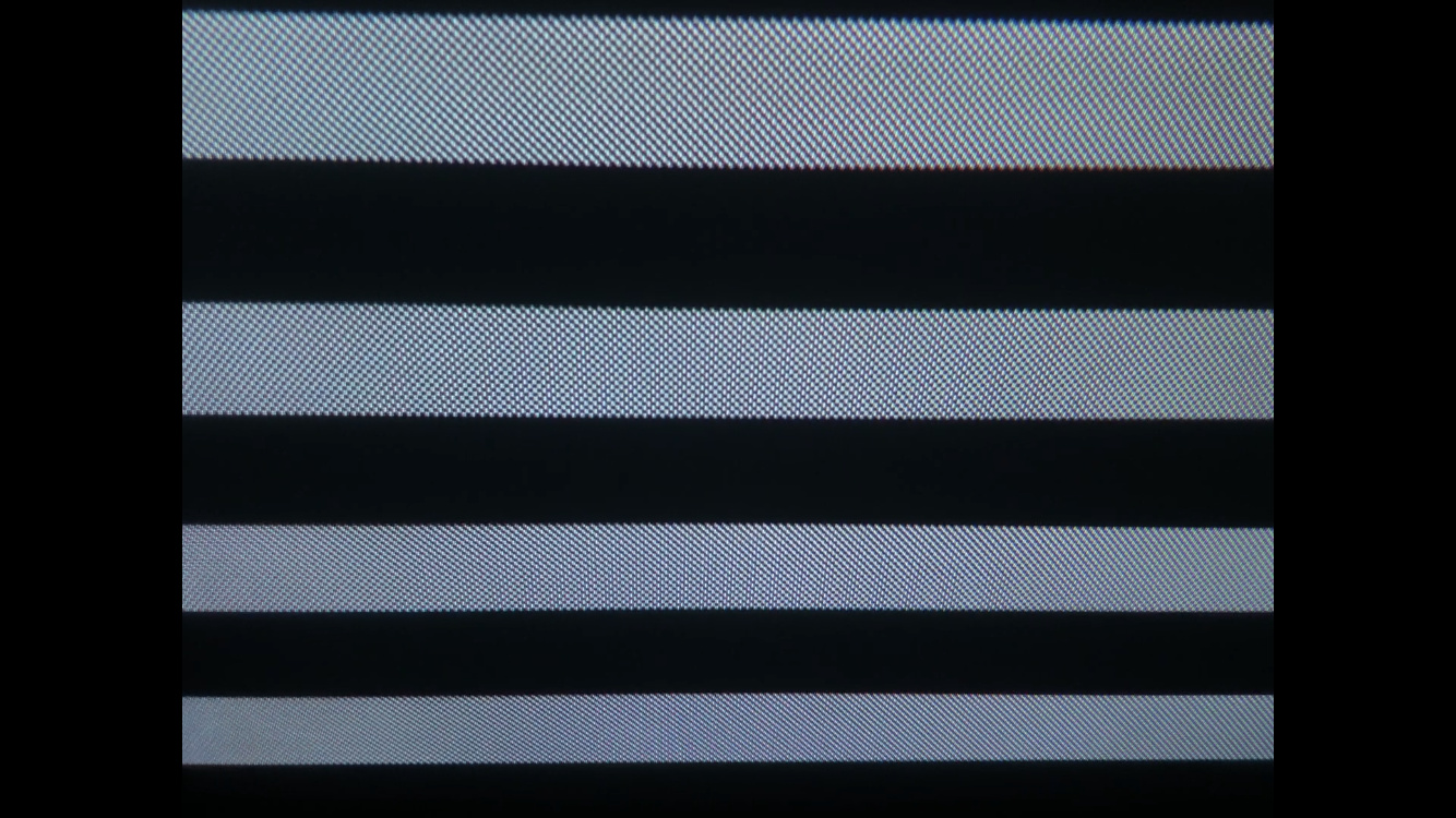
Plugging only the Y (thru a 75r resistor and 220uF cap) into the YPbPr connector gives a stable B&W image as expected. Sorry, these pictures are a bit overexposed but black levels look right to me on my CRT. PR Horizontal bars -> CC -> RGB Encoder.
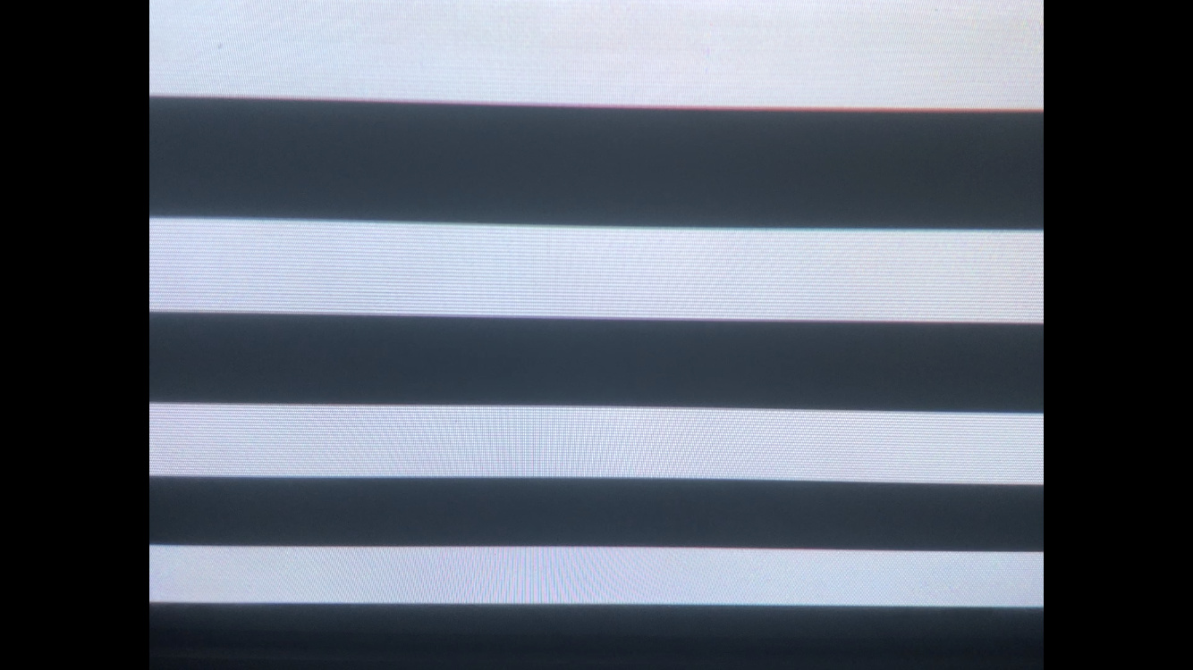
However, if I turn down the levels of any of the individual RGB channels on CC with only Y going out from the Encoder, I get a stable diagonal pattern that scrolls horizontally to the left overlaid on anything not at 0V. The checkerboard effect is just bad photography on my part–the diagonal lines point from upper left / lower right.
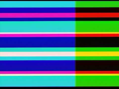
Plugging Pb and Pr from the BA7230LS in, everything looks stable when it’s a fully white signal as above. As soon as I start attenuating one of the RGB signals, the scrolling diagonal pattern appears again. The colors track properly.
If I add/remove the individual buffered RGB jumpers from the AD724 going into the BA7230LS while keeping the RGB knobs fully CW on CC, the colors look pretty close to what I’d expect–maybe a bit brighter but the patterns don’t appear.
When I have a completely black image, I can still see a little bit of purple with YPbPr all plugged in. If I remove Pb and Pr, I can see very faint scrolling horizontal bars. It’s not anywhere near as noticeable as when taking the Y with the mixed in sync from the BA7230LS and doesn’t have that wavy dot pattern at all. Could just be noise/offsets that’ll go away with not having this on a breadboard.
#41 — rempesm · 2020-09-16
Oops, just kidding–the S-Video splitter I was using was wired weird and had C coming through somehow.
Used a different splitter where it was definitely only Y coming through and now it looks great.
I’ll do some more tests shortly and post some clips.
#42 — VisibleSignals · 2020-09-16
I must admit I haven’t been following the technical details of this thread closely, but if overall luma is affecting your sync situation then the underlying problem could have something to do with your composite signal’s effective average DC offset (a white screen is basically a positive DC offset, minus sync etc). Something something grounding something something black level restoration something something DC decoupling. Wow, that’s about the vaguest I think I’ve ever been in my whole life… sorry

You would very likely benefit from some detailed scope work to determine exactly what’s going on and get some more info.
#43 — rempesm · 2020-09-16
No that’s totally fair considering how vague my descriptions are compared to providing actual measurements with a scope. All good reminders on what I should be checking while breadboarding this up.
Right after I posted that, I realized I was accidentally using a S-Video adapter that merged Y/C in a RCA jack which happens to look identical to another adapter I have that only pulls Y out. Using just Y completely got rid of the diagonal line issue I was describing above.
In any case, the YPbPr output now looks pretty clean apart from a small but still perceptible amount of noise on black which could be the breadboard or cheap cables or maybe just my CRT!
Comparing the dot crawl and overall quality I was getting on composite with YPbPr output is a night and day difference–so much sharper. Will post some captures soon. Thanks for the idea on using that signal @Fox.
#44 — Fox · 2020-09-16
VisibleSignals wrote:
I must admit I haven’t been following the technical details of this thread closely,
We had discussed technical details a bit further in DMs as well, but I guess the brief version of what I suspect has happened is that the sync injection stage creates an offset when sync is high. To get around this we need to use an open collector transistor connected to a negative voltage with an appropriate resistor which will drop Y below 0 during sync, but be high Z when sync is high. That is assuming we continue with the BA7230LS option.
If we do though, I plan on drawing a circuit to inject sync properly but I first have to decide what negative voltage to use and calculate the passive components from there. We could just use -12v since it is available, but we were already discussing using a dedicated +5v vreg for further noise isolation so why not use an additional -5v or -3.3v regulator too?
Buuuuut, we already have an acceptable Y with sync from the AD724 so we may be able to simplify the circuit so much further by doing the B-Y and R-Y operations.
rempesm wrote:
In any case, the YPbPr output now looks pretty clean apart from a small but still perceptible amount of noise on black which could be the breadboard or cheap cables or maybe just my CRT!
Comparing the dot crawl and overall quality I was getting on composite with YPbPr output is a night and day difference–so much sharper. Will post some captures soon. Thanks for the idea on using that signal > @Fox> .
Glad it got worked out. I know that we can continue to simplify and improve the circuit with a working prototype. I’ve been learning a lot from all of this reading.
#45 — Fox · 2020-09-16
rempesm wrote:
However, if I turn down the levels of any of the individual RGB channels on CC with only Y going out from the Encoder, I get a stable diagonal pattern that scrolls horizontally to the left overlaid on anything not at 0V. The checkerboard effect is just bad photography on my part–the diagonal lines point from upper left / lower right.
I just read something interesting on the YPbPr wikipedia page:
Since YPbPr is backwards compatible with the luminance portion of composite video even with just component video decoding one can still use composite video via this input, but only luma information will be displayed, along with the > > chroma dots> > ."
I think that explains the scrolling checkerboard you described when you had chroma mixed in with luma, although this is irrelevant to the final goal.
#46 — rempesm · 2020-09-16
I tried this by putting just the Y plug into the composite out and it gave the exact same diagonal line pattern as yesterday–good to know that’s chroma interference if I see that again!
#47 — Fox · 2020-09-17
Comparing Fabio’s board with Dek’s, I find it hard to believe a fab house even printed Fabio’s. There are several vias within vias. The BA7’s datasheet also demands users tie unused inputs pins to ground via a 1uF capacitor which Dek’s board luckily does. Pins 3, 4, 5 and 20 were left floating, and while the datasheet doesn’t elaborate on possible negative effects, it’s usually drift, self oscillation and noise.
Bodging some caps on these pins might help with the noise on black if you still feel like bothering with the first board.
#48 — rempesm · 2020-09-20
I did some captures to test the difference between composite, S-Video, and YPbPr as well as putting them through a Retrotink 2x for an HDMI out, all going into an Intensity Shuttle.
Just for the YPbPr outputs:
When I run the YPbPr output directly into the Shuttle, I get this weird strobing effect that scrolls downwards.
Color output:
https://www.youtube.com/watch?v=fsMCTmJizRMBlack output. You can still see the strobing faintly if you look closely. It’s more obvious on my computer monitor while capturing so YouTube might be squashing it:

https://www.youtube.com/watch?v=EnpzpCFDnDMIf I run the YPbPr output into the Retrotink 2x and then into the Shuttle’s HDMI input, the strobing almost completely disappears and there’s very little noticeable noise. Probably can still be improved.
Color output:
https://www.youtube.com/watch?v=b9APB2rt5O4Black output:

https://www.youtube.com/watch?v=YNDSOBLZfZII’m not certain how this is changing anything other than just transcoding the 480i signal into an HDMI compatible signal. Maybe I’m getting reflections somewhere and the Retrotink filters them out?
I put some 1uF caps on those pins and didn’t notice any immediate difference in quality on my CRT but forgot to capture test footage.
Looking forward to getting this built with the new PCBs when they come in next week.
#49 — Fox · 2020-09-20
rempesm wrote:
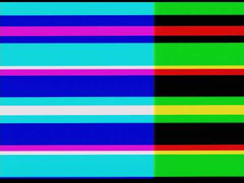
When I run the YPbPr output directly into the Shuttle, I get this weird strobing effect that scrolls downwards.
I can hardly see it because of youtube’s compression. But I can see some effect that isn’t present in the second color video. I can’t imagine what it could be due to. To me it almost looks like some fluctuation on the brightness signal and even then it is most notable on cyan and blue. Covering the left half of my screen, its virtually gone from the green/black stripes.
rempesm wrote:
Black output. You can still see the strobing faintly if you look closely. It’s more obvious on my computer monitor while capturing so YouTube might be squashing it:
Again I assume this is because of youtube’s compression, but the video is perfectly black on my laptop screen.
rempesm wrote:
I put some 1uF caps on those pins and didn’t notice any immediate difference in quality on my CRT but forgot to capture test footage.
Ok. Improvements are probably too subtle to see, but still recommended either way. Always good to cover all bases.