VGA - Eurorack interface project (I'm looking for feedback)
Category: Unknown · Tags: eurorack · Posts: 10
#1 — Pxltr2033 · 2020-04-19
Hi, it’s my first euro project and I don’t know if I did anything wrong.
#2 — VisibleSignals · 2020-04-19
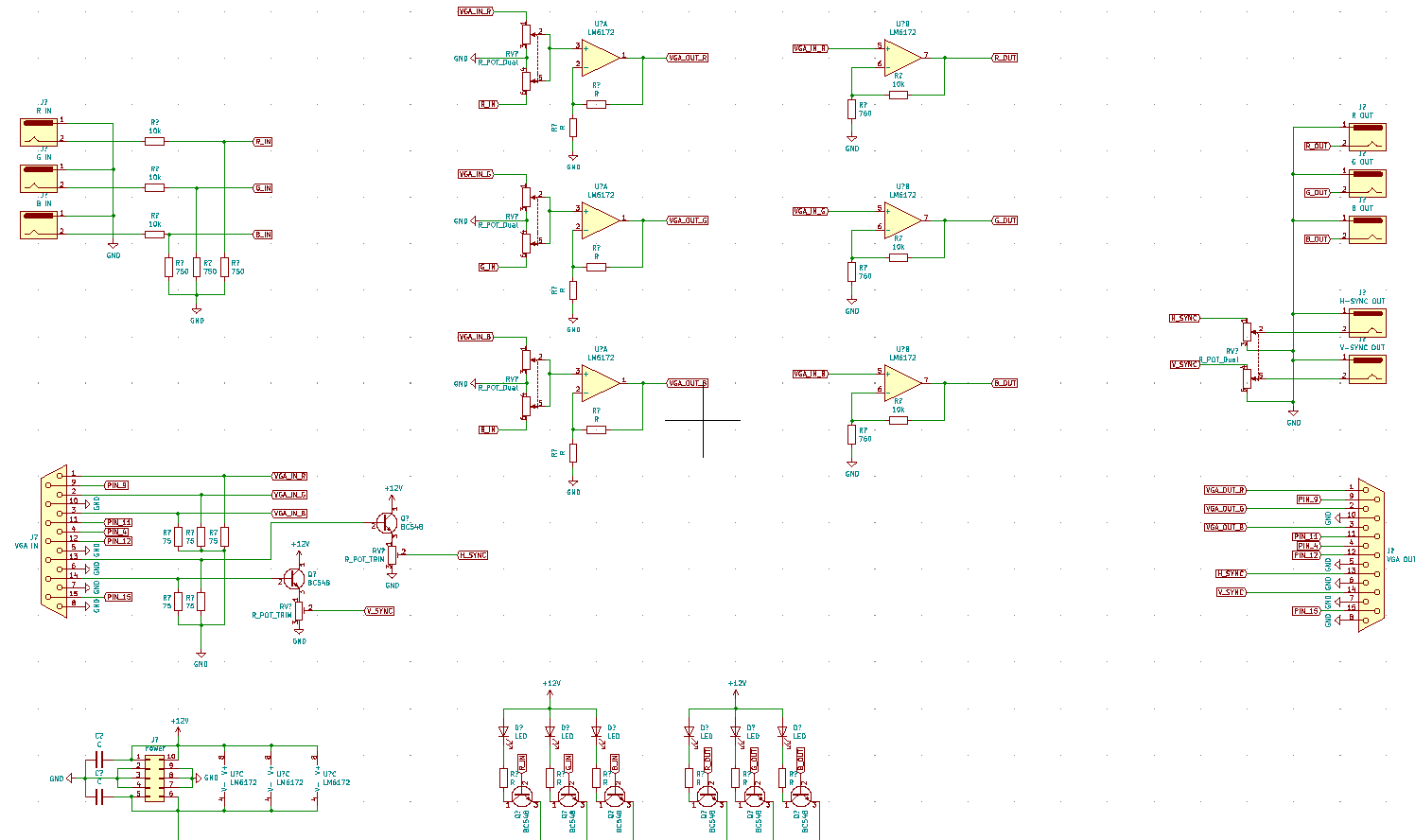
I think you should definitely build this on breadboard first, to confirm the design works the way you think it will. For example the R_IN circuit is currently configured as a 10K/750R voltage divider, giving you only 7% of the input signal being passed through - very likely not what you want. Also I’m not sure the voltage dividers/non-inverting mixers will work quite the way you would typically want them to (two signals with variable resistors into a non-inverting op-amp input doesn’t give you summing or a linear response like an inverting op-amp summer circuit would). Always a good idea to prototype!
#3 — Pxltr2033 · 2020-04-20
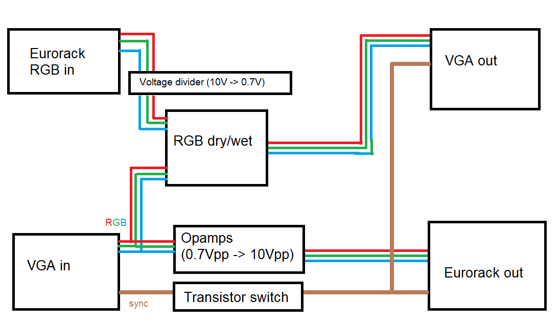
VGA operates on 0.7Vpp and I dont expect input voltage to be higher than 10Vpp, so that’s exactly what I want
#4 — VisibleSignals · 2020-04-20
Fair enough, that makes sense - and I should have seen that in your block diagram. I’m used to LZX standards, where voltages are typically 0-1V for video synthesis.
#5 — Genlok · 2020-04-23
Cool idea. I wish VGA was more supported in the video modular world.
Is this intended for use with an LZX system? Will it sync to other modules?
#6 — Pxltr2033 · 2020-04-24
nah, they’re too expensive
#7 — spar · 2020-04-24
if you’re just doing stuff with vga, i’ve had good luck mixing the rgb channels with dirty mixers to get different colors combinations.
#8 — joem · 2020-04-25
If you’re just mixing the color channels from a VGA signal, the mixer circuit in the “dirty mixer” is just a passive mixer… nothing dirty about it since there’s no sync involved.
#9 — Marizu · 2020-04-26
I originally started trying to build a VGA based system. I built a couple or basic ramp based oscillators and I injected images from a camera, through an old box that I had for video gaming (Composite > VGA). When I used that box, it would generate the timing signals, which would be passed through. Otherwise, timing would be generated by a CHA/V.
It seemed like the monitors started displaying horizontal imagery as soon as they detected a signal even if it was outside the display window that the incoming video was being displayed in.
This meant that when I added an oscillator into a signal path that also contained an incoming camera image, that image was displayed in a smaller ‘window’ that was disconnected from the left of the screen.
Remove the oscillator and it went back to full screen. At that point, I realised that I was going to have to add a lot more circuitry and add a more complex output stage. When I looked into the number of op-amps that I would need to use, the Cadets didn’t look so expensive after all, so I went LZX.
Best of luck with this!
#10 — Pxltr2033 · 2020-04-26
yeah, but I don’t want to make full video system. Only this module and maybe sync generator.
Thanks for reply!