Simple video mixer project
Category: Unknown · Tags: — · Posts: 29
#1 — reverselandfill · 2020-05-13
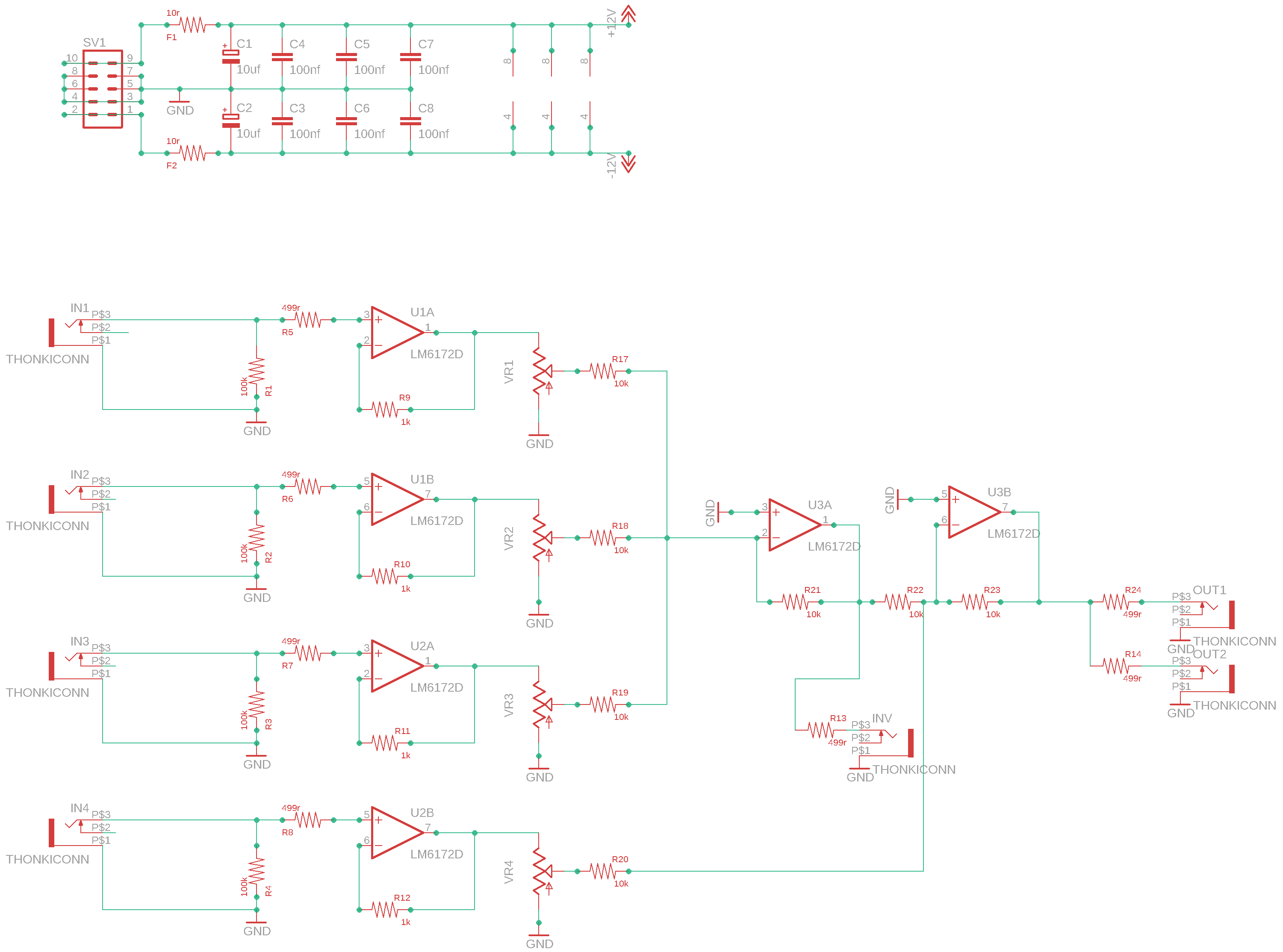
Ok. I had a layout based on the LZX / L.Larsen design of the Summing mixer.
The basic design of the Summing mixer already has a place in my custom video synth, but
I want to add some features, and make it suitable for the Eurorack format
Maybe a simple filter . I don’t know yet. I was looking at an Allpass filter for phase shifting and possible interesting feedback effect… Suggestions are welcome!
current layout & schematic features:
4 channel mixer
3 normal inputs with attenuators
1 inverted input with attenuator
3 outputs
2x normal output
1x inverted output
Sandwiched panel & pcb. No wiring, though-hole design.
Current schematic:
(the inverted output need some work I think. )
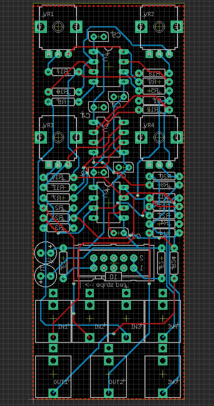
The layout for the pcb is mostly done. I have some room left…
#2 — joem · 2020-05-14
One neat thing that the MHzxER has is two switchable inputs per channel. I kind of wish I had one of those, but your matrix mixer and the cadet fader have been fulfilling all my mixer needs these days, so I never ended up building a MHzxER.
#3 — reverselandfill · 2020-05-14
as a performance option. yeah, I get it.
#4 — reverselandfill · 2020-09-08
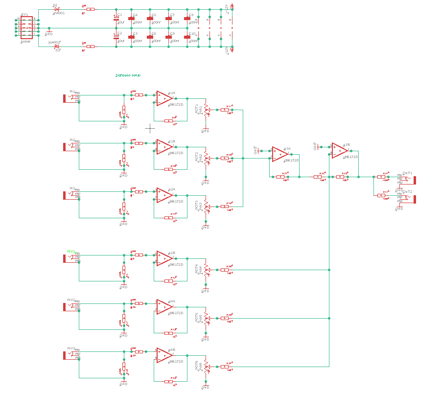
Working on this again. I was playing with assymetrical shapes and patterns. this summing mixer is perfect for it. especially with more inputs and outputs (to do feedback routing)
It now has 3 normal inputs, 3 inverted inputs, 2 outputs
(6 pots, 8 jacks, 8HP)
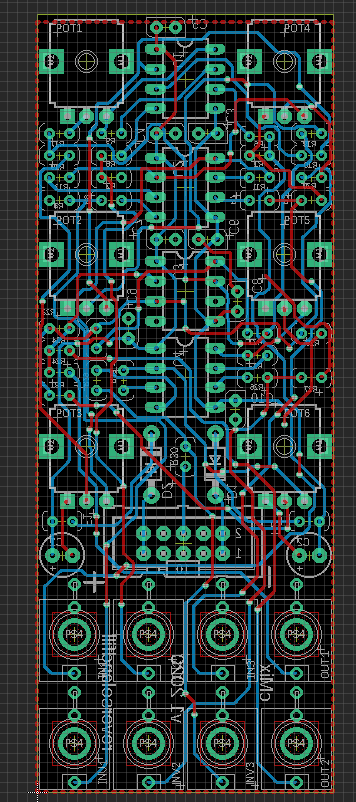
The layout is pretty tight, with vertical resistors to get it to fit!
current schematic & layout:
#5 — transistorcat · 2020-09-08
I think the main input i missed for the matrix mixer was a “thru” input (so it could be chained), but that seems less relevant here.
It’s going to be hard with the space constraints, but having the inverters go from positive to negative rather than 0-negative would allow you to use it as a 6-channel general mixer, and is also useful for modulation signals.
This of course sacrifices the ability to easily zero out the negative inputs.
#6 — reverselandfill · 2020-09-08
now that you say this, I am wondering is x3 normal inputs and 3x inverted inputs would be better .
makes sense in my head.
But the 4 normal channels give good results for pattern making… mmmh… choices.
Anyway, I wanted this project to be fairly simple. so maybe I’ll try not to let the feature creep monster get too close.
#7 — transistorcat · 2020-09-08
I mean, if they all (or all but one) normal to 0, you don’t really need them to be easy to zero and you could have them all be attenuverters
#8 — reverselandfill · 2020-09-08
mmh. I don’t really know how to do this. do you have an example?
you mean that each channel could be inverting or not , right? (the pots as attenuverters)
That would be a cool addition.
#9 — transistorcat · 2020-09-08
Generally they work by subtracting an attenuated negative 2x input signal to the input signal, so that they cancel out at 1/2 attenuation.
This link shows both the basic circuit as well as a technique to flatten the response close to the zero-point in the middle.

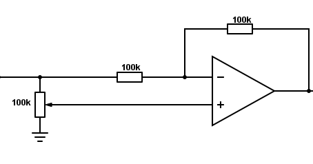
https://kassu2000.blogspot.com/2018/04/precision-attenuverter-mixer.htmlThe word attenuverter , a combination of attenuator and inverter, has become pretty standard in the modular synth world. The attenuverter d...
Link: Precision attenuverter / mixer
#10 — rempesm · 2020-09-09
Attenuverting mixers are awesome but having a wider effective resolution on a pot for precisely dialing in a mix is nice, too. That layout above looks good to me in 8HP.
I’d be interested in seeing something like the Matrix Mixer expanded to an attenuverting version (second a thru input!). More options for video rate mixer modules seems useful.
#11 — reverselandfill · 2020-09-09
I changed the pcb into a 3x normal 3x inverted mixer , this made more sense to me in terms of complex mixing ideas.
now to design the panel

I’ll test the attenuverting options for another project.
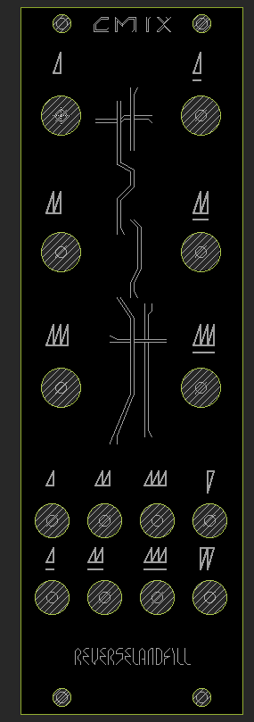
#12 — reverselandfill · 2020-09-09
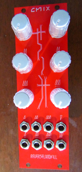
preliminary panel design: (it will be a red panel, just like the rest)
#13 — reverselandfill · 2020-09-15
the design is ready. I’ll order some PCBs soon!
#14 — rempesm · 2020-09-15
Excellent! I’d be down to snag a few of these from you once the build is confirmed.
#15 — meudiademorte · 2020-09-15
Also really interested!
#16 — reverselandfill · 2020-09-20
I’m wondering how to make a matrix mixer out of an attenuverting mixer.
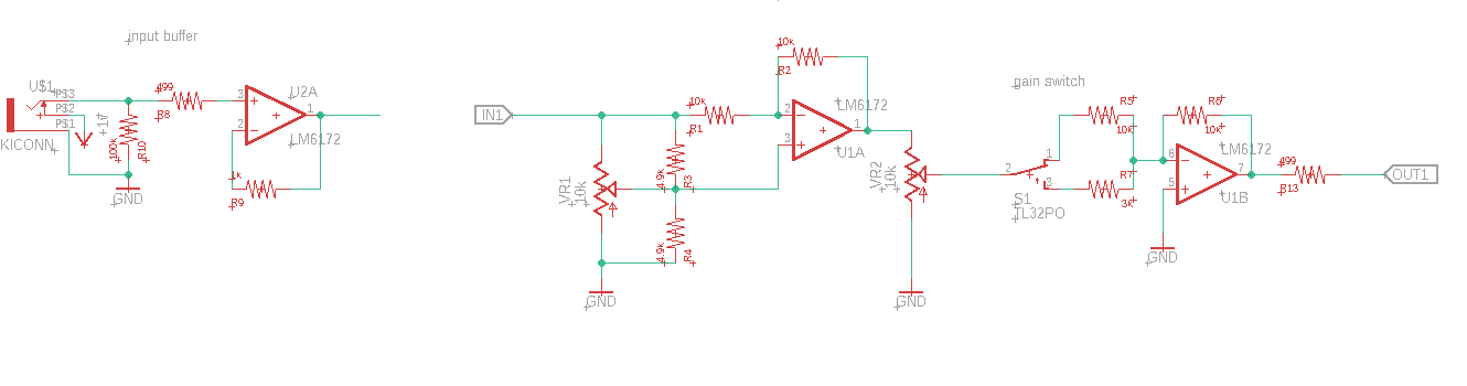
I think I can’t sum the input signals at the “IN1” net. so it must be after. (?)
So the input summing stages all must have 2 or 3 opamps to setup the signal, right?
Can I sum the inverted signal just after U1A?
#17 — transistorcat · 2020-09-21
I think i could get it down to ~one amp per input and two per output, but i’m not convinced i’d be happy with the result.
(Buffer all inputs, add all inputs in an inverting summer, feed that into another summer together with the matrix)
Alternately, you typically won’t need attenuversion in every matrix point and can get most of the benefit by having just one attenuverter per input and then have those feeding the matrix inputs?
#18 — Fox · 2020-09-21
Take a look at the input buffer used in Cadet III. That should save on 6172’s.
#19 — reverselandfill · 2020-09-21
Sorry about my unclear question.
I wanted to know at what stage I could sum the signals.
(I’m not worried about the amount of opamps)
#20 — transistorcat · 2020-09-21
In that case, the answer is “yes”. (Right after U1A)
#21 — reverselandfill · 2020-09-21
I was thinking of an expanded update for the matrix mixer. 3x3 attenuverted pots + a set of overall gain control for each channel + gain amount switches
So you wouldn’t need an inverted section, because each channel can be inverted or not.
I hope the middle point or zero is easy to set though. the overall gain might help with that a little.
What was it that was said about chaining inputs?
#22 — reverselandfill · 2020-09-22
more on topic: the CMIX is ordered.
8HP panel
3 normal ins with pots
3 inverted ins with pots
2 outs
Some mods are possible for keying effects (like the Matrix mixer), but I have added no
dedicated MODpoints as the pcb is tightly packed. so (there is) no space left!
(on the pcb I mean, not space in general)

#24 — reverselandfill · 2020-09-22
thanks, that is what I meant. edited the sentence for ultra clarity!
#25 — reverselandfill · 2020-09-30
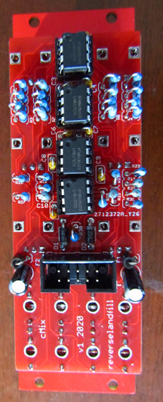
The pcb’s are in! now to test … soldering iron engaged
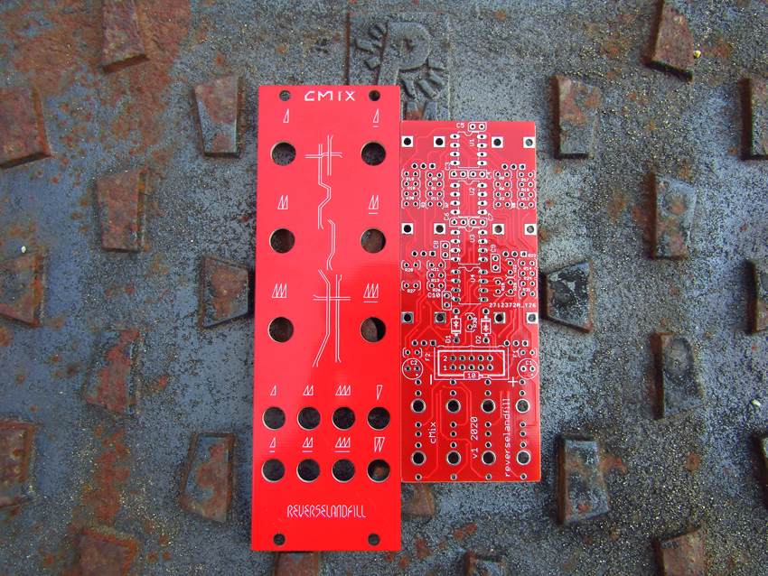
#26 — reverselandfill · 2020-09-30
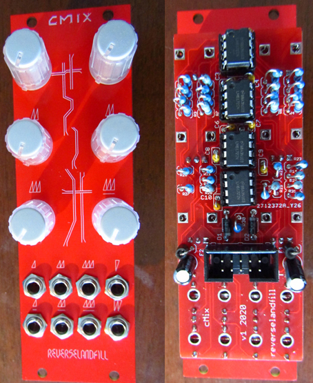
and it works!
I’ll setup an order thread !
#27 — Robbertunist · 2020-09-30
Fantastic news👏🏼
Good work @reverselandfill

#28 — reverselandfill · 2020-10-01
Bom and Schematic are here for download:

https://www.reverselandfill.org/diy/cmix-a-6-channel-video-mixer/Link: CMIX – a 6 channel video mixer – Reverselandfill
CMIX BOM v1 2020Resistorsvaluedetailsamountr1, r2, r3, r4, r27, r30100k6r5, r6, r7, r8, r14, r24, r26, r29499r8r9, r10, r11, r12, r13, r151k6r17, r18, r19, r20, r21, r22, r23, r28, r3110k9Ferrite beadsf1, f22Diodesd1, d21n4001reverse power protection2Capacitorsc1, c210uF>16v electrolythic2c3, c4, c5, c6, c7, c8, c9, c10100nFCeramic, 2.5mm8ICu1, u2, u3, u48pin socketoptional4u1, u2, u3, u4LM61724PowerSV110pinshrouded header1power cable10pin to 16pinkeyed headers1HardwarePotsb10kvertical 9mm Alpha6JacksThonkiconn8Knobs6M3 screwsfor panel mounting4Build tips
Use this order for placing the components:
- IC sockets
- 100nF caps (the kit uses vertical mounted types)
- resistors
- diodes
- ferrite beads
- power header
- polarised 10uF caps
- pots & jacks
#29 — syntonie · 2020-10-13
Just got my pcb set yesterday, many thanks @reverselandfill!
Here is a quick test, shapes are generated using CMIX (H ramp, V ramp, 3x Cadet VCO, 1x Castle VCO), then sent to VU002 for doubling, the 4 outputs goes to Matrix Mixer, then to RGB encoder, and further processed in composite using CBV002.


#30 — reverselandfill · 2020-10-20
Resistor placements to help you build the CMIX while I continue to write the build manual
see also here
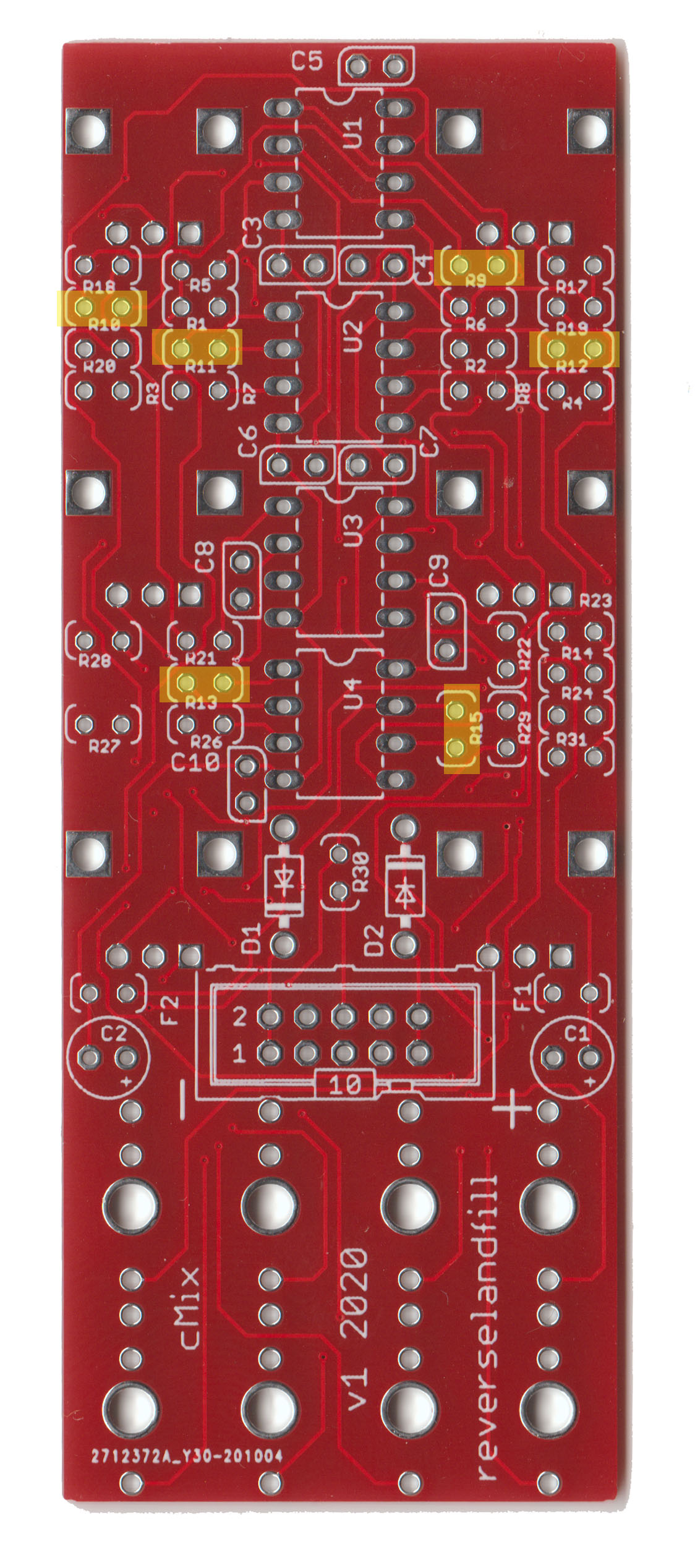
1k
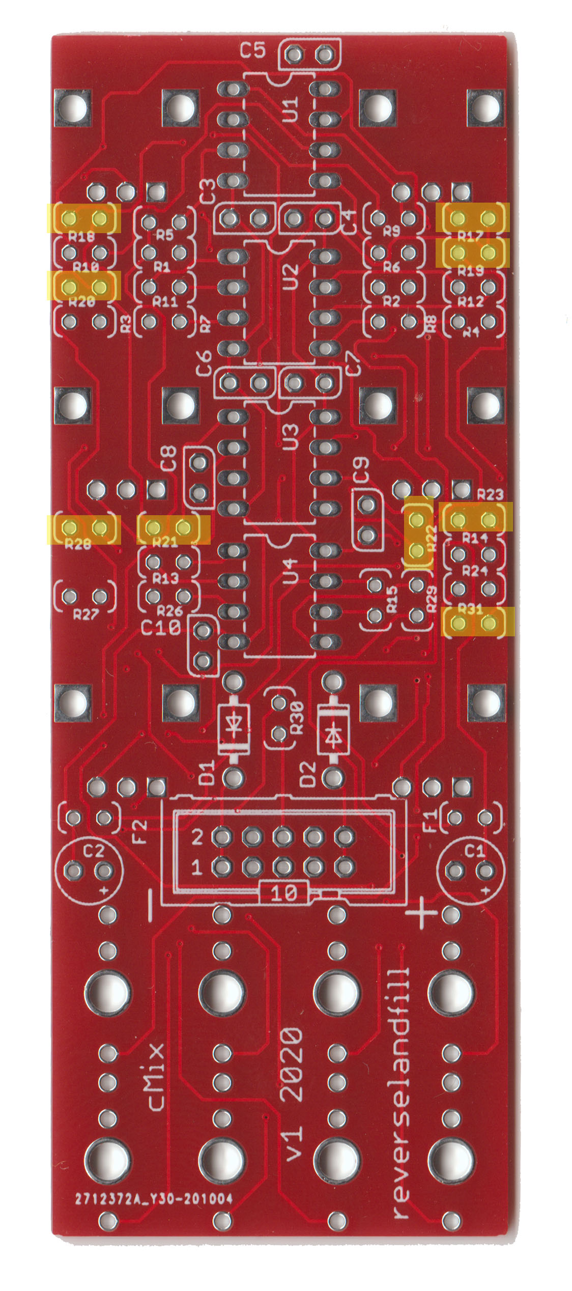
10k
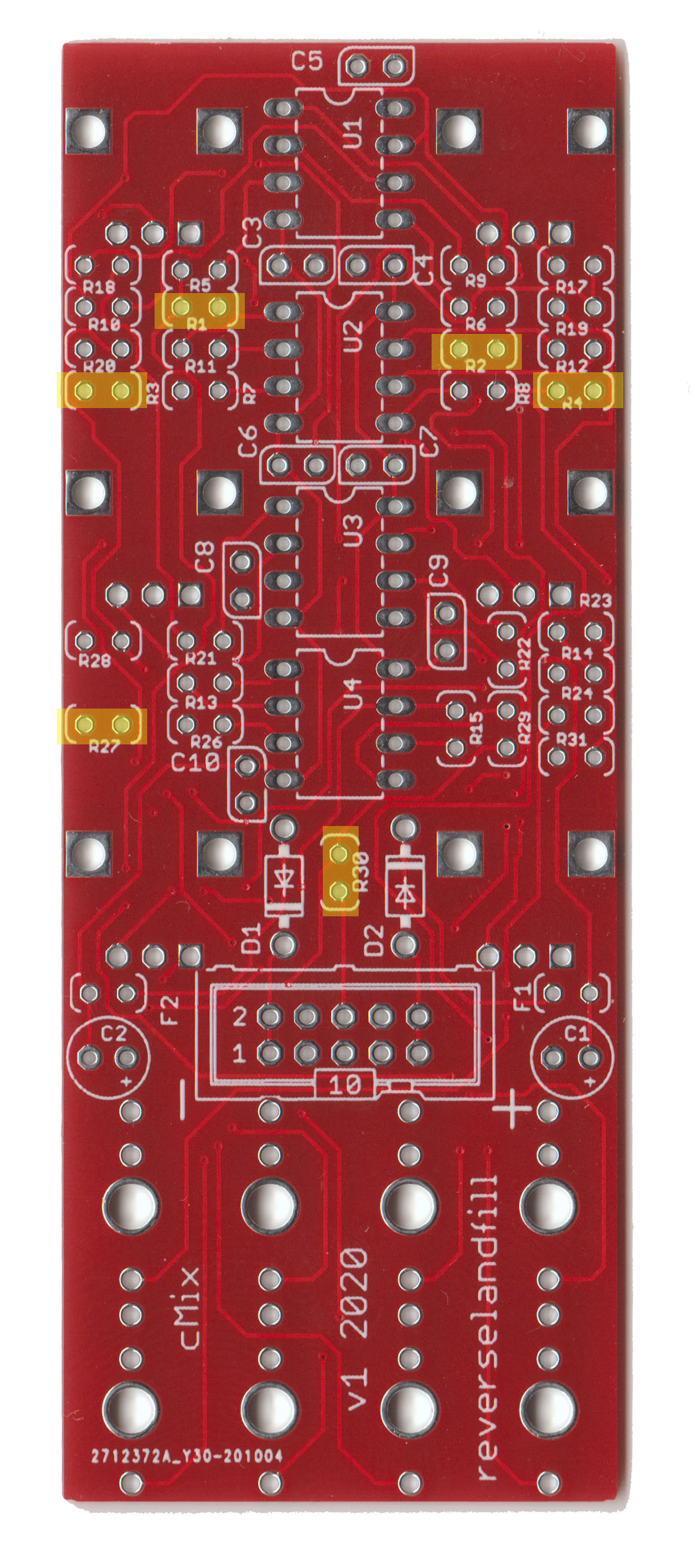
100k
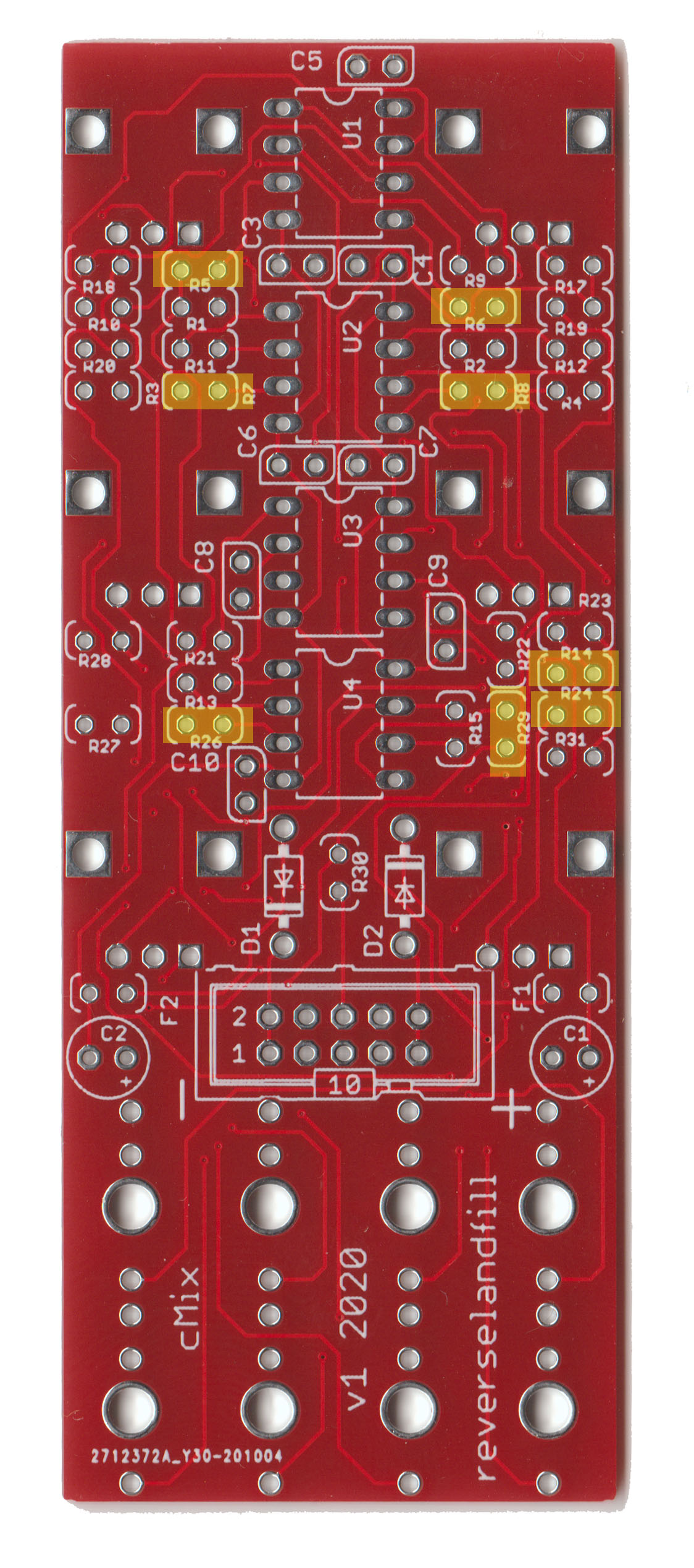
499r