Cadet Modding hints and tips
Category: Unknown · Tags: cadet · Posts: 37
#1 — reverselandfill · 2018-08-02
Hi
I thought, lets start a discusstion about modding the Cadet modules!
-Squarewave output on the VCO : there is a SQ pad on the PCB (and an extra Triangle output. J3 and J5)
-There is a Chroma output on the Encoder. not sure what this does…
-Encoder Cadet
to get the same results as showed in this clip: http://www.youtube.com/watch?v=FpOEtm9aX0M
solder the encoder jacks in this way:
connect the red tip to the switch pin of the green jack.
connect the green tip to the switch pin of the blue jack.
Now the colors are cascaded downward. Maybe I’ll add toggle switches too.
-this one is not really a mod, but useful patching technique:
The Processor module can also be used to slow the frequency of a VCO.
Simply connect the output of the Processor to the CV input of the VCO.\
Now you can get a much slower rate!
You can still use the input of the processor to get more modulation done.
Other tips I got from Lars:
(1) The C8 hard key circuit can be adapted to provide a pulse width modulation CV and output. Just send the triangle wave into the key input and threshold becomes pulse-width.
(2) There is a Square output on the C9 circuit. You can output it directly or use it with the triangle to drive a sawtooth waveshaper circuit.
If you patch the squarewave and triangle wave into a Fader module (CV in and ch1 in, you get a Sawtooth wave too. (only half though)
#2 — pbalj · 2018-08-03
maybe the chroma out is to do s-video Y-C
#3 — JonasBers · 2018-08-03
It is, according to the data sheet anyway. You need to add caps to them though. I broke mine out to the front panel.
#4 — creatorlars · 2018-08-04
Yeah, the Luma/Chroma signals are for connecting to an S-Video jack. (AD724 datasheet shows the whole circuit.) Here’s a nifty tip… you could use the Luma signal as a rear RCA sync distribution output, in case you wanted to use Cadet 1 to drive LZX modules that require rear sync in over RCA.
For the squarewave out on the VCO, I think this is just the 5V TTL level signal. Just note that if you want to send it to a jack, you need a 3.92K/1K resistor divider and a video opamp buffer (as you see on outputs throughout all the Cadet schematics.) If not all that, at least an output resistor (499R-1K.)
You can use Cadet boards like a toolkit to build larger ideas. For example, you can get the square root of the triangle wave output from C9 by using a C10 multiplier to multiply the signal by itself! That creates an expo waveform (the basis for star wipes). If you subtract the expo waveform from the original signal at double the gain (using a C7 board) you get a parabola waveform, which is the basis for circle wipes. If you then use a crossfader (C6) to fade between the parabola and the expo, you get triangle (diamond wipes) again in the center of the crossfade. And that’s how you’d patch up half of the Shapechanger module’s gamma shaper.

#5 — reverselandfill · 2018-08-05
If I read the schematic correctly, the SQ out already has a buffer (U20.2) & 499r output resistor. (?)
correct me if I’m wrong.
I’m going to try the suggested patches! Maybe I’ll make a dedicated panel
#6 — creatorlars · 2018-08-06
You’re right! And yes, let me know if I can help.
#7 — reverselandfill · 2018-09-28
hint from Lars about getting component video into a Cadet system:
You would need to modify the secondary units to share the sync signals generated by the first, but you could definitely use 3x Cadet IIIs to get component video (YPbPr and RGsB) into your Cadet rig!>>>> Visual Cortex has YPbPr input (there is an internal analog YPbPr to YRGB colorspace converter.)
This is great news!
Question: is it possible to get more video sources into the system? (I mean 2 camera inputs?)
#8 — Agawell · 2018-09-28
You need a tbc for that…
#9 — creatorlars · 2018-09-28
Yes, if both cameras are synchronized (which requires cameras with genlock input capability) then you can just use 2x Cadet III input. Or you can find an external time base corrector/frame synchronizer with genlock.
#10 — reverselandfill · 2018-10-14
Another question: Is is useful / possible to have multiple RGB Encoders in one rack?
I was thinking about layering a feedback path with synthesis
#11 — luix · 2018-10-15
Oh yes its totally posible, it just need sync as far I know so you will have to dupe that signal.
Im starting to think that would be a nice to build/design SYNC buses for large DIY cases because using ribbon cables for sync signals when you havre lots of modules (like 9Us of cadets) can cause problems I guess?
I have 3 x Cadet VCOs, 2 x Cadet Ramps and I dont have any problems but maybe with 10 or 15 sybc dependant modules would be too much for ribbon cables to keep the signal clean
#12 — reverselandfill · 2018-10-15
yeah I was thinking about this too. I already have a lot of VCO’s.
DIYing those male ribbon cables is a bit of a hassle. I’d rather have a board.
ha. I even tried to convert my DIY power busboards for sync, but that did not work because the ground layer
covers pins 3-8. in retrospect that was a big duh.
Maybe I do a run of boards, if enough people would want one.
How much positions would suffice?
My power busboard has 9 shrouded headers. see here:my site
The pcb size: 16.5 x 4.2 x 1.2 cm
I could make a larger pcb. but that is more expensive. the pcb’s are easily expandable by connecting faston cables.
#13 — transistorcat · 2019-01-30
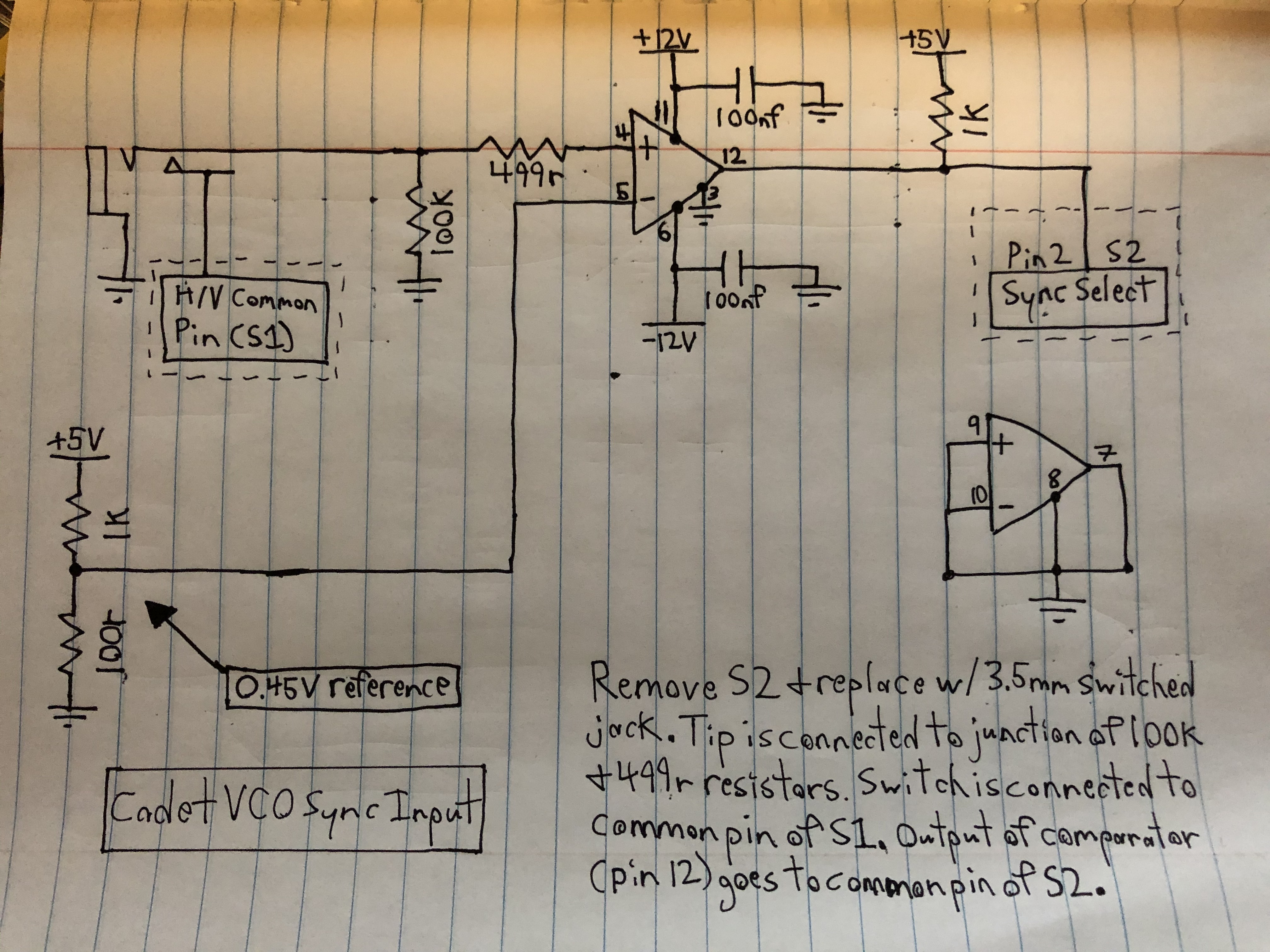
@creatorlars On the early cadet mockups i’ve seen the oscs seem to have a separate sync input
Did this go away due to panel space, or is there some technical issue preventing me from say, connecting a jack -> coupling cap + pulldown -> inverter to the switch where the +5 goes today?
#14 — creatorlars · 2019-01-30
The Cadet VCO has never had separate sync input as far as I remember, so you should be able to add one if you want. For “LZX spec”, you would use a comparator with threshold at 0.5V rather than a transistor, since it needs to be able to sync from 1V signals. LM319 is a good option in this context.
#15 — luix · 2019-01-30
I’m gonna propose/try to do another mod to my VCO/Ramps Cadets regarding the SYNC, in order to use less cables
The mod is simple to JUMPWIRE the HSYNC and VSYNC from the video sync header, to be connected directly to the CV/GATE bus channels from the power header.
In that way Cadets will be compatible with VisualCortex without the extra sync connector.
The bus that @reverselandfill desgined is amazing btw

#16 — luix · 2019-01-30
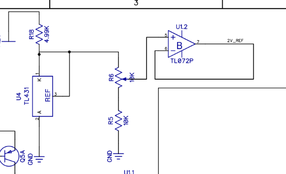
Another one… to replace the pedestal trimmer on the Cadet VCO, with a wire potentiometer into the panel to have (not CVable) but control over that parameter.
Its 10k trimmer R6 on the first page of the CadetVCO Schematic
#17 — cinema.av · 2019-01-30
I’ve always been curious about replacing the trimmers on ramps with actual pots so you could scale the output in realtime. But why do that if you already have something like the TVP or the single cadet processor.
#18 — reverselandfill · 2019-01-30
yeah, that is a useful mod. The trimmer has much control !
Another VCO one I was thinking about:
replace the H/V (and maybe the sync/unsynced) switch with a CD4066. I’m not sure if it gives good results , but if I flip the switch fast manually, it looks cool. I wonder what the effect would be to use audio / video rate
It would be better to use a 74HC series equivalent. and maybe a buffer / comparator on the inlet?
#19 — pbalj · 2019-01-30
the sync on the sync buss is 5v, whereas the sync on the power buss is 1v.
#20 — creatorlars · 2019-01-31
For the VCO, one “super build” option would be to combine the C9 board with other cadets to add extra functions…
- Add C7 mixer + C10 multiplier on the triangle output and you have a Prismatic Ray core with offset and voltage controlled gain/inversion!
- Add C8 hard keyer on triangle output for voltage controlled PWM output.
- Gamma shaping can be done with the C10 or C9 boards, by using them as a squaring circuit. If you mult the input signal to CV + IN simultaneously, and input is 1V scale, you now have an exponential waveshaper.
In some of the above cases you may omit certain pots or jacks and just hardwire connections. All of the circuits exist in function blocks in the Cadet lineup to make a mega VCO with PWM, AM, multiple waveshapes, offset, etc.
#21 — transistorcat · 2019-01-31
The mockup@thonk seems to disagree

Anyways, thanks for the info
#23 — luix · 2019-01-31
ohhh got it, didn’t know the levels were diff. cheers Phil
#24 — creatorlars · 2019-01-31
Yeah, looks like initially we were going to require H/V sync be patched directly each time. We decided to have the switch instead.
#25 — luix · 2019-04-08
Cadet “Pedestal” mod… its not the same pedestal like in Prismatic Ray but you can control (kinda) the gradient (+ pwm?) of your Cadet VCO.
#26 — rempesm · 2020-05-23
I used one of these switched pots for the pedestal mod in place of the H/V switch so I can still sync the oscillator and change the oscillator’s range. That switched pot is a little bit too big so you have to solder the legs of the other pots and switches where the PCB is flush with the panel’s edge for it to fit.
Really worth breaking that R6 trimmer out along with the square wave output on J3.
#27 — a_green · 2020-06-16
how hard would it be to modify the Scaler for 10V to 1V? I would like to interface my buchla modules with the Cadet series.
#29 — a_green · 2020-06-16
totally, yeah, I am currently using attenuators. Wasn’t sure if it was as easy as, say, halfing the values of the resistors used without choosing different op amps.
#30 — VisibleSignals · 2020-06-16
This should be quite achievable. Looking at the schematic, R4/R1 (etc) is a voltage divider which divides the input voltage, but it also acts as a termination to ground for the input signal (which will generally be driven from the output op-amp of another module through 499R) so the resistor value calculations are more complex than they at first appear (and probably why some of the BOM and schematic values differ). Your best bet is going to be experimentation - I suggest you solder in some single pin sockets (e.g. https://www.taydaelectronics.com/30-pin-dip-sip-ic-sockets-adaptor-solder-type-single-row.html) for the resistors and then you can easily try different values until you find one that works the way you want. If you don’t have a range of resistors already then grab a “resistor assortment pack” for a few dollars. Stick to values similar to those specified for the 5V->1V version, and either increase R1 or decrease R4. Informed trial and error is a great way to learn DIY!
Definitely no need to change the op-amps.
#31 — pbalj · 2020-06-17
R1 and R4 set the attenuation. R11 and R12 set the gain. R30 and R31 set the offset voltage.
For calculations, look up non-inverting opamp amplifiers.
#32 — Fuzzy_Pause · 2020-06-25
Just finished building a set of cadet modules.
(As an aside big thank you to everyone posting here!! Browsing this forum has been incredibly helpful both for the building process and in starting to understand the wonky world of video synthesis!).
Playing with the oscillators I do wish they were just a tad slower at their slowest setting. Based on the schematics it looks like R2 is the resistor to play with, is that right?
#33 — rempesm · 2020-06-26
First thing to try is plugging a DC offset, e.g. from a Cadet Processor, into the CV input or mixing it with your other modulation. When vertically synced, my VCOs usually show about 1 bar with the Frequency knob fully CCW and with a DC offset from Processor, I can get it to go as slow as ~1/4 - 1/2 of a bar. Horizontally synced (EDIT: oops, unsynced), I’ve been able to get down to some somewhat slow pulsing LFOs.
I haven’t tried modding that resistor but it seems like a reasonable place to start experimenting! You could just install some pin headers in its place and substitute values close to 16.5k on either side to see what the effect is. Let us know what you find out!
#34 — Fuzzy_Pause · 2020-06-28
Thanks for the reply!
I’ve played around with using the the processors to get extra range out of the oscillators but was thinking It’d be nice to free the processors up for other duties. Though as I’m getting to know this system I find that I often run modulating voltages through a processor anyway so maybe it’s not such a loss.
But, curiosity will probably get the better of me & it seems too fun to poke around in the circuit to not! I’ll report back with any findings.
#35 — Fuzzy_Pause · 2020-06-30
Looks like R2 will change the maximum frequency of the oscillator, but not the minimum. Using a lower value will increase the maximum frequency and vice-versa. It could of course be that it’s changing both but the effect is much more pronounced in the higher frequencies…
Either way though I don’t think this is the solution I’m looking for - the range of the oscillators feels pretty right, I was mostly looking to get the lowest frequency (without any modulation) to sit a little below one cycle.
Back to the schematics

#36 — reverselandfill · 2020-07-04
you could make a simple adjustable voltage source design to mod the CV input of the VCO
#37 — rempesm · 2020-07-14
Thanks for the pointer on this! I put this together on breadboard today and it works great.
I probably should have been less lazy and set the voltage divider to exactly 0.5V but it seemed close enough with the resistors I had on hand.
#38 — jestern · 2024-01-19
As far as I understood so far the mods allow PWM only on the triangle wave (via Pedestal MOD or Cadet 8), is that correct? is there any way to get Sine out somehow?
#39 — rempesm · 2024-01-20
You’d need a separate triangle to sine shaper. There’s some good starting points here: