Color Chords schematic for diy?
Category: Unknown · Tags: — · Posts: 8
#1 — warpigs666 · 2020-07-27
Hi. Is there a schematic / pcb option for the Color Chords? Haven’t had any luck finding one to purchase outright and wondering about diy options. I really like the design.
#2 — rempesm · 2020-07-27
It’s not available as a DIY option but it doesn’t look like a super complicated circuit. Looking at the PCB quickly, it’s just 6 quad op amps (ADA4851-4), 12 transistors and a bunch of resistors/caps set up in a particular order.
If you’re after a matrix mixer in general, Reverselandfill’s Matrix Mixer is a good option that’s readily available to DIY although it doesn’t do the priority based subtraction that Color Chords does.
#3 — warpigs666 · 2020-07-27
I’ve been looking at that Reverselandfill matrix mixer. I do really like the priority based subtraction though.
#4 — sean · 2020-07-27
If I recall correctly, the intention was that some Color Chords functionality was going to be replicated in an upcoming Automata series instrument.
(Not that that helps you now, obviously.)
#5 — reverselandfill · 2020-07-27
what is this “priority based subtraction” ?
#6 — wednesdayayay · 2020-07-27


https://lzxindustries.net/LZX Industries designs and manufactures creative instruments for the arts of video synthesis, analog image processing and visual art installations.
Link: LZX Industries - video instruments for video artists
the opacity controls in the associate 3 patches video it shows how that works/looks
I haven’t messed too much with your matrix mixer yet (need to sort a good power supply for the second case the 4ms row power gives me some crackles) but I think it might be similar to how your invert input works except instead of an input over all three there are manual controls per layer
#7 — rempesm · 2020-07-27
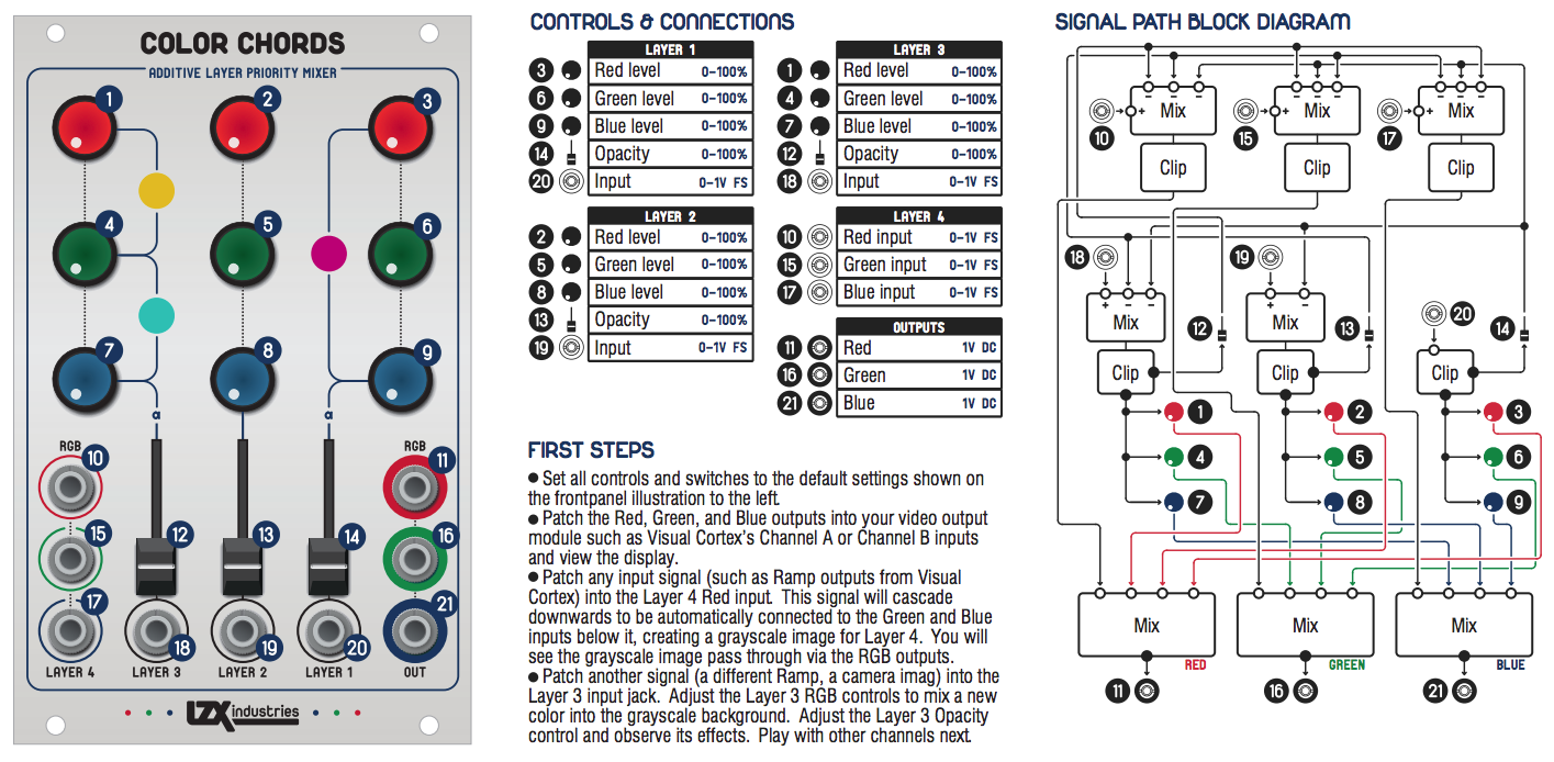
I remember Lars explaining how each layer is subtracted from each other in a particular order but I can’t seem to find that quote now. This graphic that was released awhile back might shed a little light, though:
#8 — wednesdayayay · 2020-07-27
you can see from the signal path diagram that it starts with
layer 1 (B) subtracts from layers 2 (G) ,3 ® ,4 (RGB)
layer 2 (G) subtracts from layers 3 ® ,4 (RGB)
layer 3 ® subtracts from layer 4 (RGB)
layer 4 is not subtracted from anything
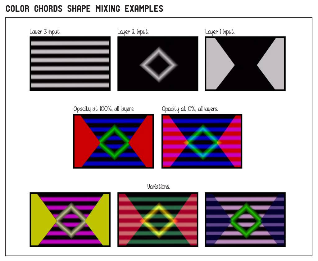
so you can see that layer 1 sits on top of the mix if the opacity controls are all at 100%
it really makes shape layers pop from each other