Matrix mixer expanded edition
Category: Unknown · Tags: — · Posts: 57
#1 — reverselandfill · 2020-09-25
OK. I’m finalizing the design for the expanded edition.
Current features:
Each of the 3 columns has:
3 normal channels
1 inverted channel
switchable gain setting for the normal channels and the inverted channels
6 inputs jacks, 3 output jacks
15 potmeters total
HP: unclear as for now. bigger than 14HP
There are 3 potmeters that control overall gain (currently only the normal channels, not the inverted)
I might change this and add a attenuverted channel instead of the inverted one. I think I can then set the overall gain with one pot for all these channels
I might be tempted to make all channel’s attenuverters. but this may not be ideal for zeroing out certain channels.
Are there features you want added?
There was some talk about chaining. please give a detailed setup idea.
#2 — wednesdayayay · 2020-09-25
I love that each channel will have its own inverted input!
is there any kind of normalization between the inverted channels? So if you plugged a key into inverted R input would it cascade across to the others?
I’m not really worried one way or another about attenuverters.
The overall gain pots seems like a nice added bonus
RGB pre patching?slightly different take on chaining
it could be really interesting to have a system for pre patching RGB signal chains between modules behind the rack.
So if you have a matrix mixer module and an output module with this pre patching setup you would have a cable behind the front panels connecting them together. So if you patched a RGB video from visual cortex into the matrix mixer it would automatically go to the output module even with nothing patched on the front panel. However if you patched with the matrix outs this normalization would be broken.
How I'm using chainingRGB out from Memory Palace > Polar fringe > your matrix mixer > visual cortex channel
this allows me to get the positive and negative keys from the PF while also passing through the original unprocessed signal. I do some coloring with your mixer and then send to the cortex for compositing vs another channel
it is helpful to reduce the amount of multing that has to happen in a system.
I would have to mult the RGB signal off before sending it around otherwise.
so for a matrix mixer it would have a set of pass thru RGB outputs
I 100% get it for the polar fringe. I could see it being nice for a matrix mixer but not essential.
#3 — bentoncbainbridge · 2020-09-25
Ooo! exciting news…
Martijn, do you have a rough sketch of the panel? It helps me to wrap my head around the options. My initial reaction is that I’d prefer attenuverter channels to the overall, post-mix RGB gain.
#4 — reverselandfill · 2020-09-25
wednesdayayay wrote:
is there any kind of normalization between the inverted channels? So if you plugged a key into inverted R input would it cascade across to the others?
yes, that is possible. good that you mention it

wednesdayayay wrote:
pre patching RGB
I don’t know how to achieve this, as my output module does not have inputs on the back. does a VC has this?
wednesdayayay wrote:
reduce the amount of multing
So you’d want 2 sets of outputs , 6 instead of 3?
I can buffer these, or give them a resistor at least.
There is more space on the panel, so this could be possible
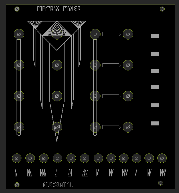
bentoncbainbridge wrote:
a rough sketch of the panel
something like this. note that this design is very preliminary.
I’m still deciding on the type of switches (low height slide switches would be preferrable)
and the pots / jacks / switches location, width of the panel etc.
#5 — reverselandfill · 2020-09-25
Oh yeah, I also added a 1v reference input to the jacks
to do matte color mixing.
The previous Matrix mixer design was capable of doing this, but a 1v ref voltage will make it more precise. I have to think about the normalisation of this feature.
option 1: jack 1 copies the 1v to the next input. when a jack is inserted, the 1v is removed from the whole chain
option 2: each jack has a jumper to set it to 1v or previous input normalisation.
#6 — wednesdayayay · 2020-09-25
reverselandfill wrote:
I don’t know how to achieve this, as my output module does not have inputs on the back. does a VC has this?
the visual cortex expander kind of does this but it outputs RGB on the back (it has solder points there isn’t a header installed).
the difference is the expander doesn’t work if it isn’t plugged in to the cortex.
but if instead of a cortex expander those RGB signals got sent to the matrix mixer you could patch with “nothing” plugged into the front panel.
the idea just popped into my head while I was reading this thread
it could make for an extremely tidy system. I know with the expander you have to have it sit right next to the visual cortex or else there is some potential noise that creeps in so maybe this is just a pipe dream.
I’m mostly just thinking out loud with this idea
with chaining modules if it had 6 outs that could be neat
“channel 1” would be the regular output that is processed through the module
“channel 2” would be an unprocessed copy of whatever comes in at the input
this could be useful for that wonderful parallel processing that really makes video work sing!
#7 — reverselandfill · 2020-09-29
wednesdayayay wrote:
with chaining modules if it had 6 outs that could be neat
With chaining I think of connecting several modules together.
If I add 3 outputs that copy the input signal, I have to rethink the normalisation option…
bentoncbainbridge wrote:
attenuverter channels to the overall, post-mix RGB gain.
What is the user case for this?
Is it useful to set the whole 3 channel mix to -1v?
I see this mixer as a possible output module, so a voltage of 1 to 0 to -1 is not really usable.
Normally one would only use 0-1v , right? (or maybe a bit higher to get some clipping / softkeying)
#8 — bentoncbainbridge · 2020-09-29
bentoncbainbridge wrote:
I’d prefer attenuverter channels to the overall, post-mix RGB gain
let me rephrase that:
“Rather than a post-mix RGB gain, I’d rather have attenuverters on the 6 inputs”
I hope that’s clear?
In other words, for me the downstream RGB gain pots are redundant, and less useful than attenuverters. The downstream post-mix RGB gain pots remind me of the LZX Color Encoder and the inverted channel reminds me of the first edition of the Video Blending Matrix. With attenuverters for each input, you don’t really need either the invert channels nor the post-mix gain.
#9 — reverselandfill · 2020-09-29
ok. but if you have attenuverters on all channels, you do not need the ‘inverted channels’
so 3x3 matrix with attenuverters = 9 attenuverters
I have to think on this.
I rather like the idea to have downstream gain , but maybe that’s just me

It would act as a macro control for color mixing / feedback settings\
#10 — ringer · 2020-10-02
Hi Martijn, any idea when the pcb’s will be ready?
#11 — reverselandfill · 2020-10-03
not yet, as I am still figuring out the feature set.
but I expect somewhere next month
#12 — bentoncbainbridge · 2020-10-04
ok. but if you have attenuverters on all channels, you do not need the ‘inverted channels’
correct, all channels could be attenuverted, making the dedicated invert channels unnecessary
downstream gain
personally, for my work flow I would balance all the input channel levels with the 9 individual attenuverters. in your example, the feedback input levels can already be controlled if every channel has an attenuverter.
for downstream color tweaking, I usually prefer ‘proc amp’ style controls (brightness/contrast/hue/gain) or something much more sophisticated like R/G/B and Gain for separate luminance bands (as with the Videotek SDC-101) or even software based color correction tools (Look-Up Tables in VDMX, Red Giant filters, etc.)
However, I love the idea of one downstream master attenuverter knob to affect all 3 channels, in order to fade to black or white like the Roland V4
#13 — reverselandfill · 2020-10-08
I did a simulation in Falstad. looks like this works.
the only thing I am not sure about is the effectiveness of the global gain pot, as it might be difficult to set it to zero (because of the both positive and negative input) - should this be an attenuverter too?)
I have to test the gain switches, which are now located before the non-inverting amplifier.
and should I add some sort of clipping? max voltage is now +9v if all pots are up and the switch is set to 3x amp
#14 — transistorcat · 2020-10-08
Might i suggest some sort of “soft” clipping past ±1V?
This would make no difference as long as you stay inside the limits but would be an interesting effect you can access by intentionally going outside the limits (e.g. by turning on 3x on an already full-scale signal)
#15 — reverselandfill · 2020-10-08
thanks for your reply. yes , you might suggest! I’m learning a lot while designing this
what kinds of soft clipping are there?
diodes?The 3x gain has cool effects, but more is not useful
#16 — transistorcat · 2020-10-08
I think most approaches have some sort of amp with a resistor in parallel with antiparallel diodes in the feedback network. I can’t find a good example right here/now, but i can try to sketch something after work
#17 — reverselandfill · 2020-10-08
hard clipping:
#18 — transistorcat · 2020-10-09
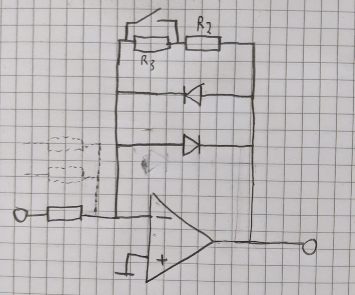
Yesterday turned out busier than planned, but something along these lines should work:
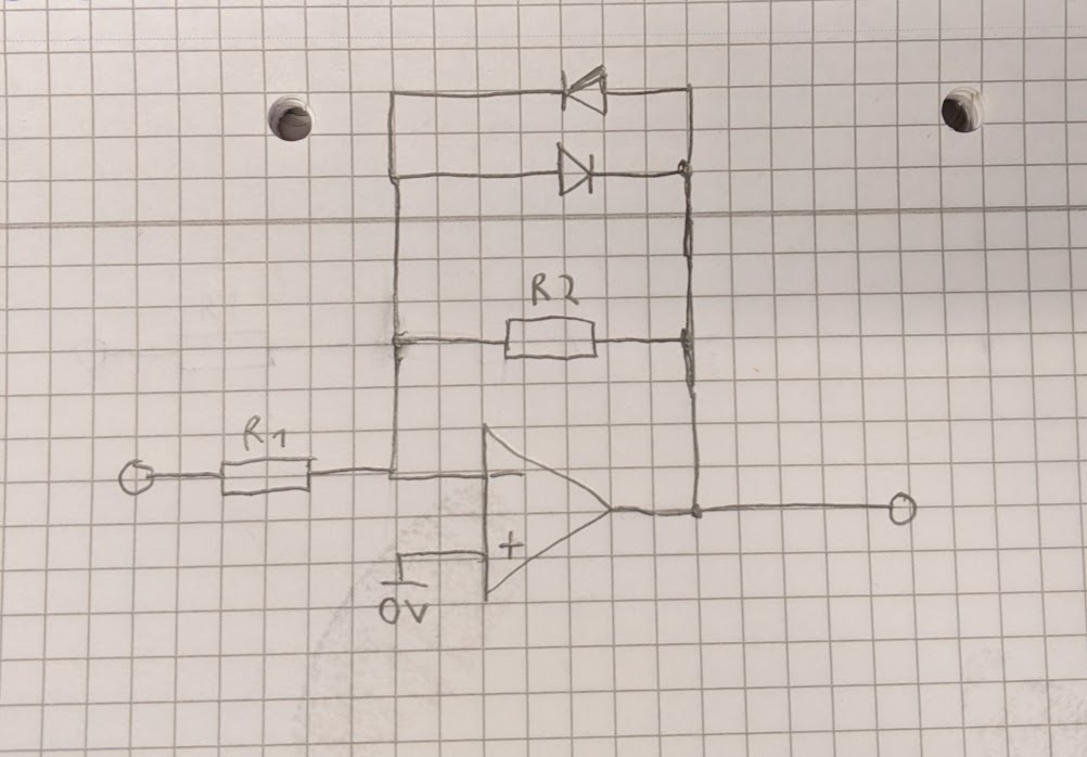
The general idea is that at low output voltages R2 dominates the response giving a mostly linear output, but as the feedback current reaches into the milliamp range the diodes will increasingly absorb a larger portion.
#19 — transistorcat · 2020-10-09
This circuit is inflexible in clamp level since it is a property of the diodes, so you’d have to have another amp at the output to adapt it.
Alternately, i think you can get it to have a decent response clipping at around 1V by using two sets of antiparallel diodes in series instead of just one.
The ratio of R2 to R1 sets the gain in the linear segment, and their absolute sizes should change the “softness” of the clip
Edit: My brain is broken today - but on second thought i’m pretty sure the absolute sizes just shifts the cut-off rather than affect its shape.
#20 — reverselandfill · 2020-10-09
I’ll test it in the simulation.
So if I understand correctly: this should be placed as 2nd stage in the matrix mixer? (after the summing resistors).
or not?
example:
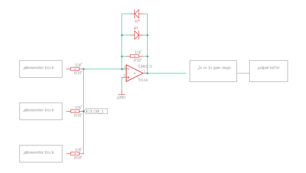
#21 — transistorcat · 2020-10-09
That would work, but i for some reason thought the 3x/1x stage would be pre-mix.
If this is to still make sense, the 3x/1x switch would have to manipulate R2 (R39 in your schematic) otherwise the clipping will provide no help in the 3x case.
I have not tested or simulated this specific circuit, but apart from that it looks good
#22 — reverselandfill · 2020-10-09
The 3x soft key function gives the extra effect. Lars said they use this in their modules too.
Maybe I did not understand this correctly. There are some clipping blocks in those modules.
Color Chords example:
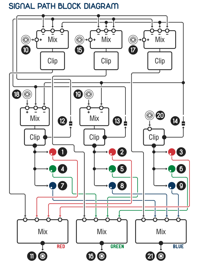
I just want to make sure there is no 9v situation possible, so that is why I placed the soft clip portion there (where the max voltage would be +3v)
But I’m really in new waters here, so correct me if I’m wrong!
For the 3x / 1x switch I have to choose a location where I don’t have to switch between too many resistors (so after the mixing stage) so I can use a simple switch (spdt or dpdt) to change the whole ‘column’ at once.
This could in theory also be at the first mixing stage.
#23 — transistorcat · 2020-10-09
Someone else might be able to chime in on exactly what the LZX designs do, but i think what we want is for the gain to be pre clip.
This should be possible by having the switch switch between R2 values which is possible with a SPDT or even SPST
#24 — reverselandfill · 2020-10-09
ok. I’ll try some setups in the simulator.
#25 — VisibleSignals · 2020-10-09
The Cadet II encoder has a brilliant clipper circuit that I have re-used in a few of my designs. It’s definitely worth spending the time to wrap your head around its subtleties and cleverness.
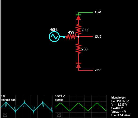
#26 — reverselandfill · 2020-10-13
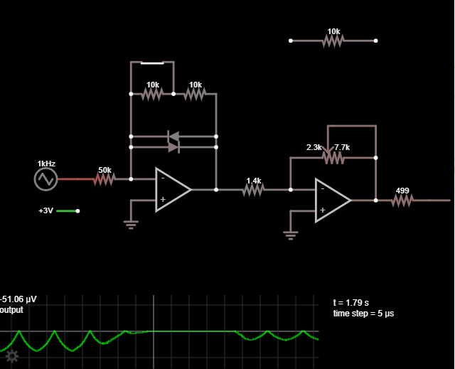
here is a simulation. it clips the top , but not the bottom of the waveform.
#27 — transistorcat · 2020-10-13
I still think the cadet precision clippers are a bit overkill for this application, but the problem you’re seeing is because you are measuring the output at the wrong node
#28 — reverselandfill · 2020-10-13
ha, you are correct.
this is better, but I can’t seen to get the right clipping settings for a ‘max state’ of the matrix mixer, as in 9 volt. even 3 volt is turning the waveform in a squarewave
#29 — reverselandfill · 2020-10-13
I’m going to try your suggestion, and think about it some more.
#30 — transistorcat · 2020-10-13
It’s going to need some tweaking, but i really like the idea of being able to overdrive the mixer and then attenuating it just a bit back down to get some nice soft nonlinearity.
As long as the parameters are right it would still be (mostly) linear from 0-1V for a more clinical standard case. (while still keeping the output from going too far outside the limit)
#31 — reverselandfill · 2020-10-13
This seems to work (with the gain switch), I not math whizz: I do not seem to be able to get into the 1v range.
note: Not sure if the switch config is correct yet. was this what you meant?
edit: this one is a bit better.
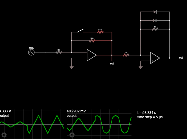
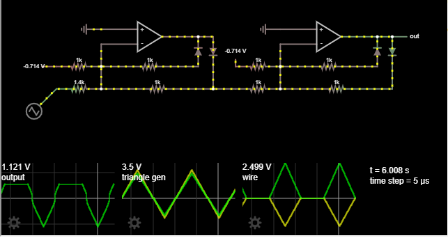
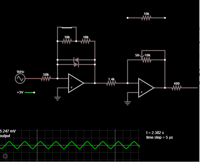
#32 — reverselandfill · 2020-10-13
with an extra gainstage at the end. this works pretty good in most scenarios. but I have the feeling this method is not optimal, I mean, it might be possible to use less opamps.
but it has interesting waveshaping options when using the attenuverters.
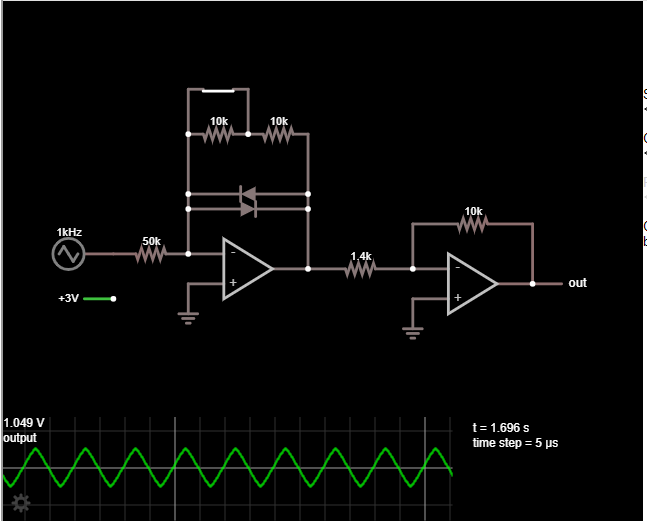
#33 — transistorcat · 2020-10-13
I was thinking pretty much this
You could also have them parallel like in your example, but that mostly just complicates the math.
#34 — reverselandfill · 2020-10-13
ah, that is clever! I will simulate it, to see what this does to the waveshapes and levels
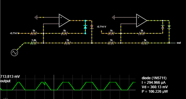
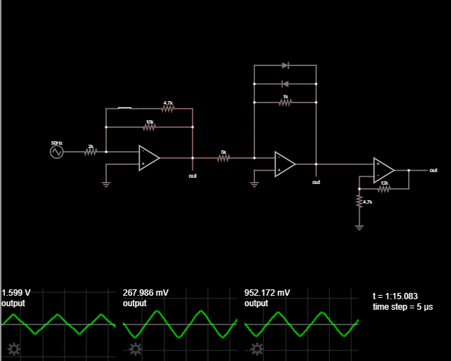
#35 — reverselandfill · 2020-10-13
this works. the ranges are a bit fiddly. but workable I think. playing with the values a bit more…
now I have to see where I put the gain pot. it was supposed to go where the 1.4k resistor is now. but that won’t work I guess. mmmmh
#36 — transistorcat · 2020-10-13
I’m not sure if the master gain being post-limit is such a bad thing, as that would allow you to attenuate after the soft clip?
#37 — reverselandfill · 2020-10-13
edit: nevermind - this looks good
I hope this can close it enough - 10k pot
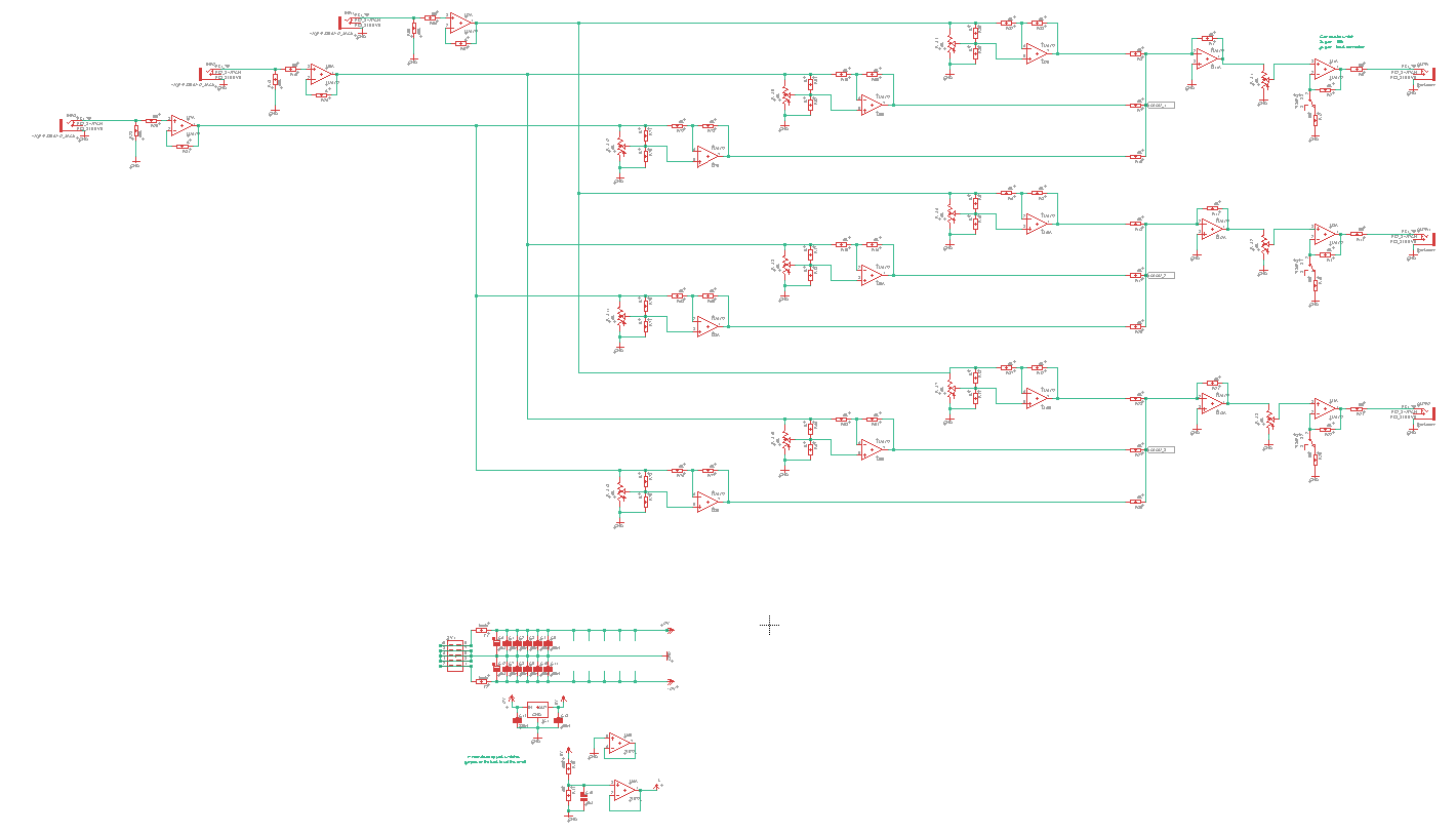
#38 — reverselandfill · 2020-10-14
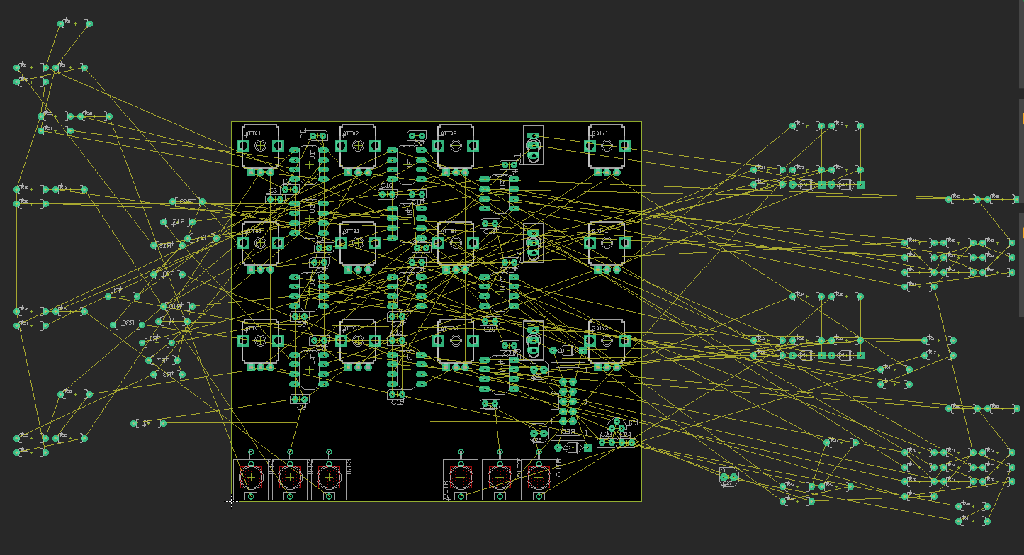
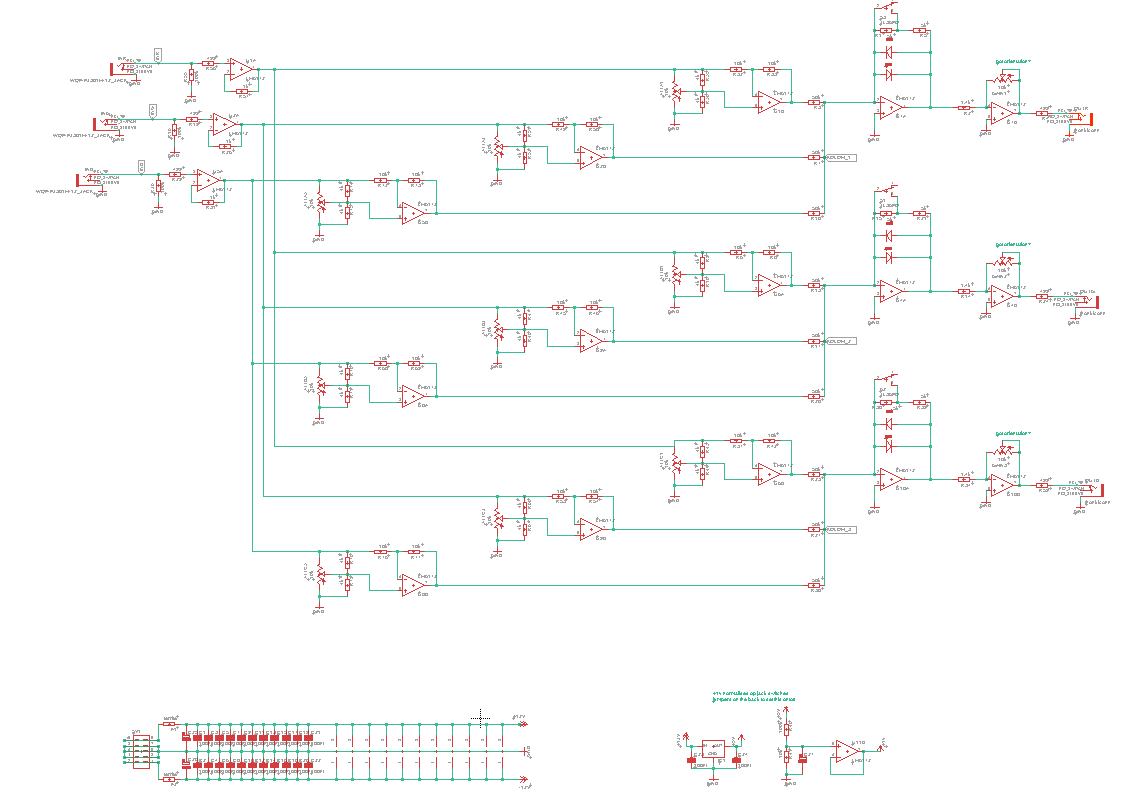
layout check.
Let’s see if I can fit this all one one PCB
#39 — reverselandfill · 2020-10-14
Jack connection ideas:
A: there are 3 inputs, I can give them ‘direct multiple outputs’ , which save you patching time.
The ‘direct multiples’ would just be connected to the input jacks. like regular multiples
I have to see if I can work something out with the normalization, as I wanted to connect +1v to the switch of the 3 input jacks, for matte color outs
B: the output jacks. I can make multiples here too. for easy patching
like this:
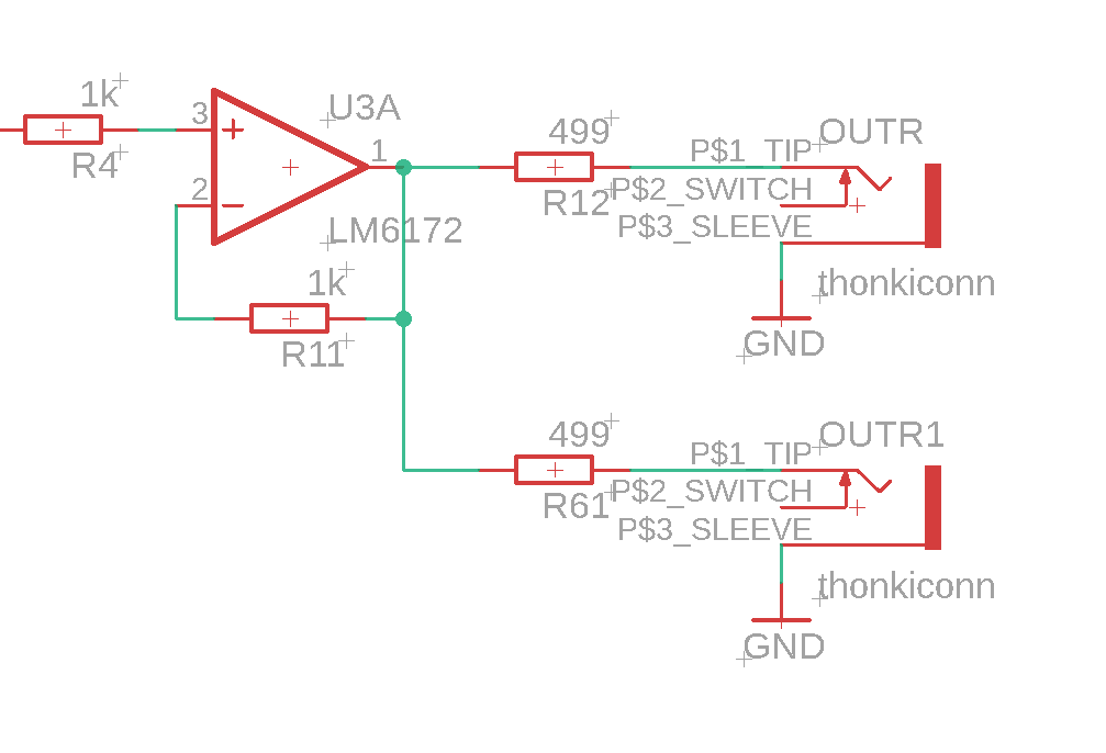
this would mean that there would be 12 jacks.
#40 — transistorcat · 2020-10-14
a) I don’t think the final set of amps are needed, the output of the last variable gain stage is already a strong driver.
b) Any specific reason why the pot in the final gain stage is in the feedback loop rather than just scaling the input to ground before the amp?
c) Rather than having multiple outputs, could we have unity gain inputs for each of the colors?
Otherwise, this is starting to look good
#41 — reverselandfill · 2020-10-14
a) ok, I was uncertain about that. …soo many opamps
b) when I try that in the simulation, I can’t get it to work properly . There has to be some amplification else the signal is too weak (300 to 500mA)
c) do you mean, 3x jacks straight into the clipping stage, bypassing the attenuverters?
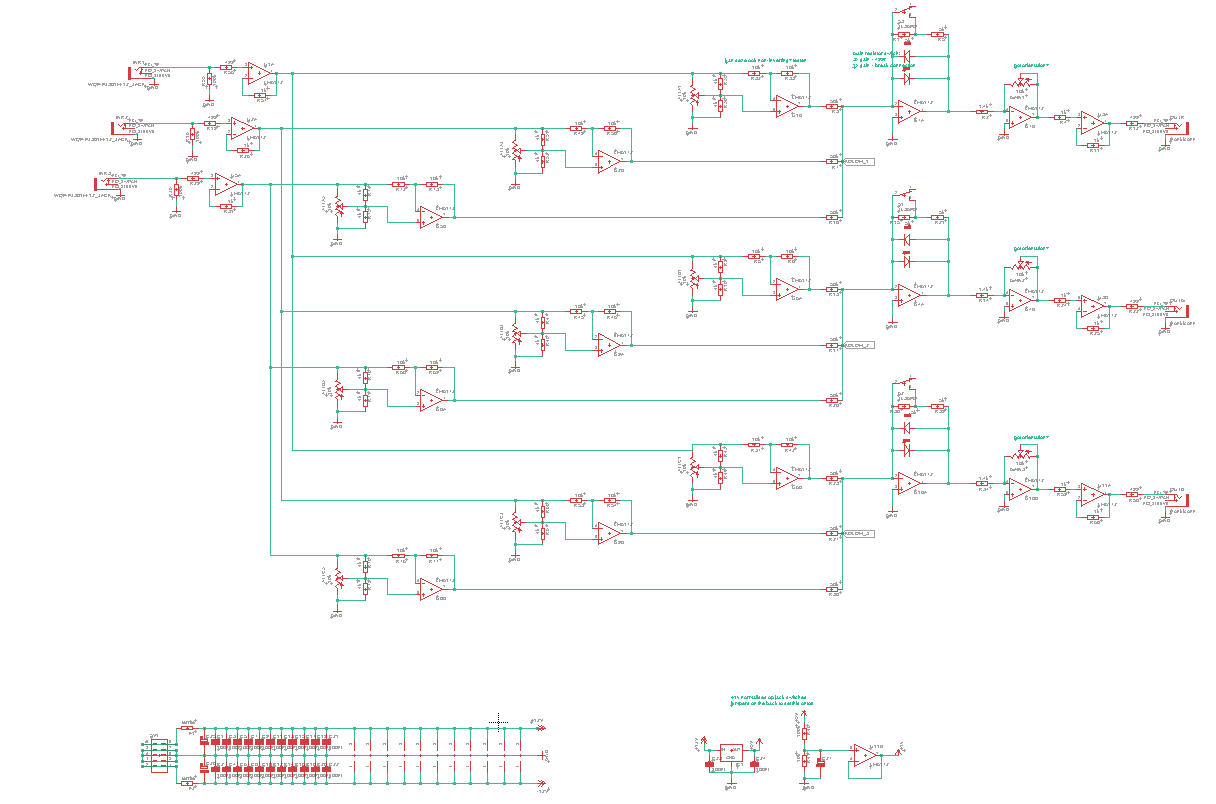
#42 — reverselandfill · 2020-10-14
update
#43 — Robbertunist · 2020-10-14
It’s great to see the progress on your matrix mixer @reverselandfill & especially to see the skill sharing dialogue between you @transistorcat

Regarding the pcb layout, my only suggestion would be to use the Analog Devices ADA4851-4 IC, its 4 op amps for about $2.50 and would substantially reduce the cost of a complete DIY through-hole version when compared to the price of the LM6172. The ADA4851-4 is an smt component but maybe if can be mounted/fitted at the factory where the PCB will be produced. Just a suggestion, nothing more.
#44 — Robbertunist · 2020-10-14
Here’s a link to the datasheet.
https://www.alldatasheet.com/view.jsp?Searchword=ADA4851-4YRUZ-RLLink: ADA4851-4YRUZ-RL Datasheet, PDF - Alldatasheet
#45 — Robbertunist · 2020-10-14
@reverselandfill, the resolution is quite low on the screenshot so I can’t read the fine print. I count 19 op amps, are they all LM6172s?
#46 — reverselandfill · 2020-10-14
there are 10 opamps in the latest version (dual LM6172’s)
I’ll check the ADA4851. They are 1,89 euro when you buy +100 at Mouser.
That is pretty cheap. runs on ±5v . ±12v? not sure is this is possible/ or needed.
What do you think @transistorcat?
SMD might be necessary, because of the amount of parts . I was already considering this.
#47 — Fox · 2020-10-14
Looks like JLC has both 6172’s and 4851’s in stock for some auto-populated boards. Thats who I use for smt boards.
#48 — reverselandfill · 2020-10-14
yes me too. might be an option then. Although this would be the first time that I would use pre-populated boards… exiting
#49 — Fox · 2020-10-14
I can help you out if you need. For auto populated boards, you need to create a BOM and Centroid file pertaining to their format and file extensions.
#50 — reverselandfill · 2020-10-14
Thanks for the offer! We’ll see when the moment get there.
I’m unsure as of now if I go that route. (SMD and pre-populated boards)
First things first: getting all the features packed into it
#51 — transistorcat · 2020-10-15
For A) and B):
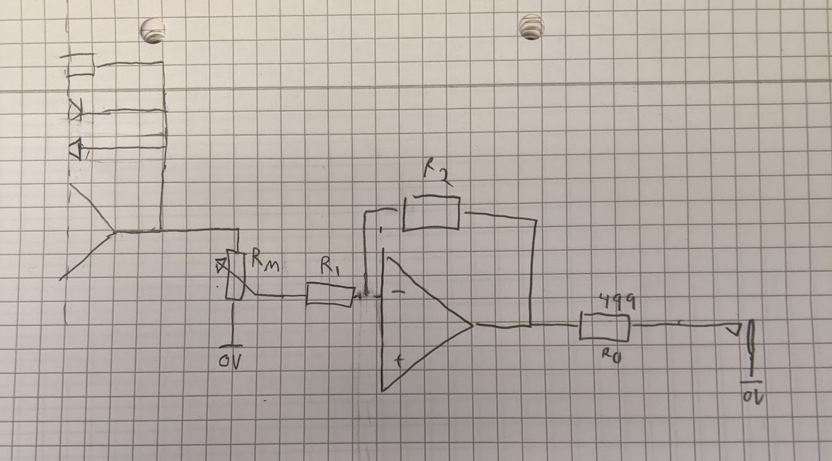
A) This should work, the output is still looking into a strong driver at the same level through the same 499R resistor.
B) This should work, as long as R1 and R2 are at least as large (ideally larger) than Rm.
My guess is that R2 should be ~2x R1 or slightly smaller than that, so having them be e.g.12k and 24k should give ok gain and a linear enough response.
For C) i was thinking like the THRU inputs on the processors, after both the limiter and the master gain.
When i suggested it i was thinking to just sum it into the post-limiter amp (assuming the pot is moved), but that would leave it inverted, i guess.
Pre limit like you suggest might be the best, and that should be possible without requiring any extra amps.
The idea is that if you have a full RGB background, there is currently no way to get it into the mixer without using up all three inputs
wrt. smd i can easily solder anything that doesn’t require reflow (like BGA and QFN) so for me this makes little difference. The lower cost should be weighted against the extra cost/work for the 5V regulators and the required protection diodes on the input, as well as the DIY-friendliness for others around here
#52 — transistorcat · 2020-10-15
If you’re going to be using the ADA4851, the input buffers from LZX Patchable Standard Reference Design Schematics is a very good starting point
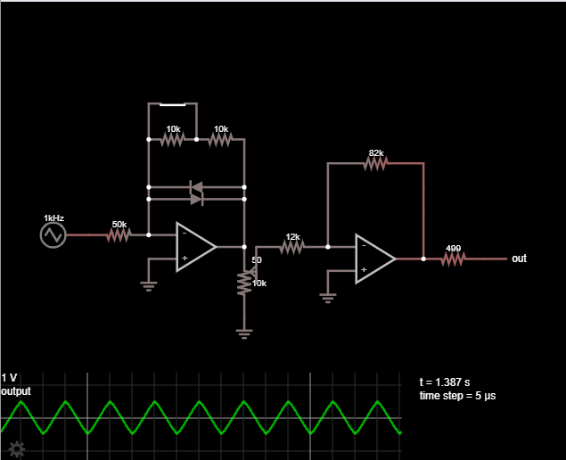
#53 — reverselandfill · 2020-11-07
this looks ok. if I make r2 82k and r1 12k, it comes to 1v output.
The 3x gain switch takes it to 1.2v and has a rounded triangle shape.
if the input voltage is 3v , it becomes a weird sine shape of about 1.7v
The max voltage can be lowered with r2, so I can adjust that value when I get the prototype.
I’ll work on the ext inputs. if I use the SMD opamps, maybe I have some to spare to invert that signal before that last opamp (so that becomes non-inverted)
#54 — reverselandfill · 2021-05-20
I’m reviving this project.
I have to refresh my memory a bit, as this project got quite expansive !
Maybe I’ll do a TH prototype version first (with 10 lm6172’s) to see if it all works
I don’t yet understand how to replace the LM6172 with the ADA4851 in this whole project.
#55 — wednesdayayay · 2021-05-20
very excited to see this moving along again!
#56 — phosphenes · 2021-05-20
What’s the current list of new features?
#57 — reverselandfill · 2021-05-20
3x3 matrix with attenuverting pots per channel
3x gain control per row
3x switches to set the gain to 1x or 3x with diode clipping
3 inputs
3 outputs
1v normalled to RGB channels for matte color mixing
I might add extra inputs and outputs, but I have to see what type of config I will use for that.