3trinsRGB+1c to LZX Adapter PCB
Category: Unknown · Tags: diy · Posts: 72
#1 — jeffbbz · 2020-10-01
So the Gieskes 3trinsRGB+1c to LZX Adapter PCB has been sold out and out of production for a while. What is the best way to go about making one? The page has what looks part of the pcb layout and of course there is a schematic. Is my only choice to learn how to layout a pcb based on the schematic and that picture or does someone have a gerber file they can send me so I can print a pcb? Or an extra adapter PCB I could buy from you?
#2 — Rik_bS · 2020-10-01
It almost looks simple enough to be laid out on perfboard - could this be an option for a DIY kludge?
#3 — vhsdestroyer · 2020-10-01
Or if enough people would like to purchase someone could get 5 to 10 pcbs made…
#4 — rempesm · 2020-10-06
If there’s sufficient interest, I’d be up for laying this out with a few additions to make it a 4HP module (I have my 3trins racked). I was able to snag one of the expander PCBs back when they were available but added a few other simple mods to my 3trins to fill out a 4HP panel.
- Three gate inputs (using LM339/CD4066) tied to the RGB vertical / horizontal range latching buttons
EDIT: oops, forgot I also tied the 4th switch to the vertical adjustment button. Personally don’t use this much since you can’t control the speed or direction of the scrolling but you can get a Diver-ish H/V scrolling of external input video with this
- CV control over brightness
It would be nice to have them all on one proper PCB instead of on bits of stripboard. It would still require a little bit of soldering wires to points on the 3trins’ PCB.
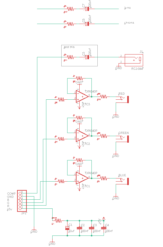
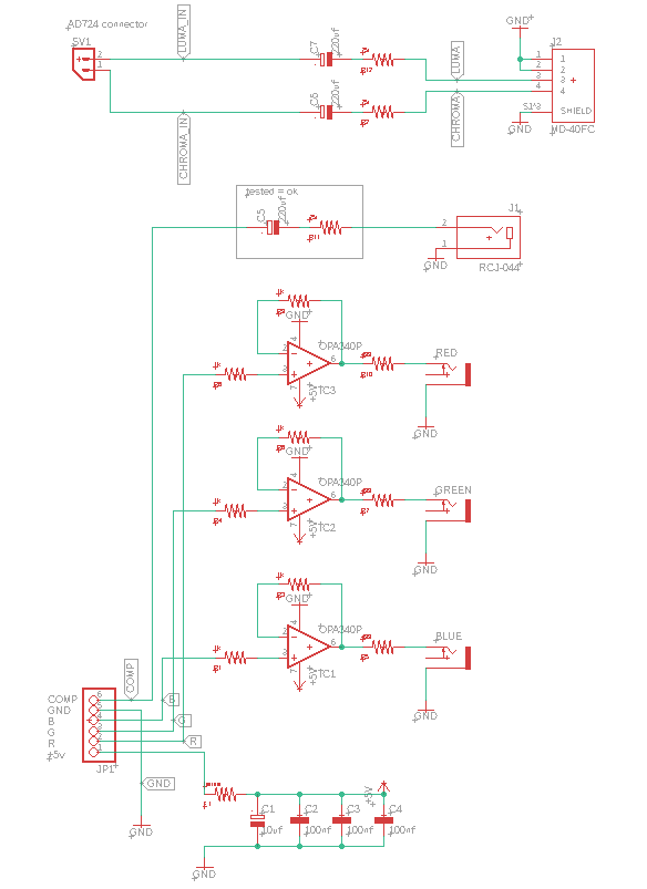
That reminds me I need to try adding a S-Video output to mine at some point. The 3trins uses the same encoder IC as Cadet II (AD724) which just requires a 220uF cap and 75r resistor in series to both the Chroma and Luma pins which are broken out. I added this to my Cadet II and it works great.
#5 — klenkstar · 2020-10-06
I would definitely pick one or two up if someone made some pcbs !
#6 — Driftwood · 2020-10-07
I would also be interested in one.
#7 — Maytoast · 2020-10-07
I’m interested in one if anyone builds it!
#8 — mrfang · 2020-10-16
Someone recently did this:

https://oshpark.com/profiles/OrgiaModeLink: OSH Park ~ Shared Projects
#9 — mrfang · 2020-10-16
OSH Park is the most expensive way to do this though. $17.50 for a board that would cost under $1 elsewhere if someone ordered a few.
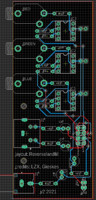
#10 — reverselandfill · 2020-10-24
I might do a run. is an eurorack version preferred or is just a pcb fine?
#11 — reverselandfill · 2020-10-27
I mean, a mountable PCB with an eurorack panel and some kind of cable to the 3trins. (MTA or so)
#12 — reverselandfill · 2020-10-27
basic setup:
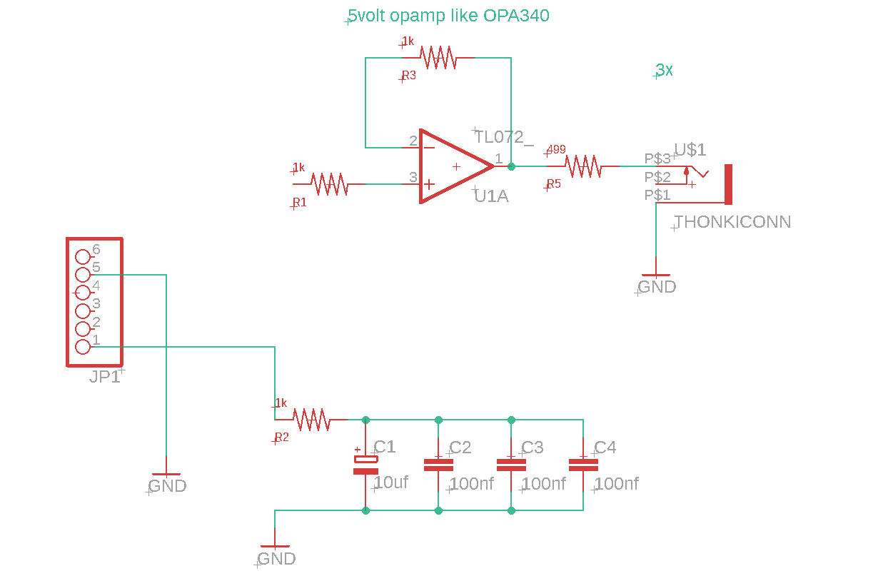
the original pcb has a few DNP resistors connected to +5v
what was the purpose of these? Why did they got cancelled I mean
#13 — VanTa · 2020-10-27
I remember something about the output from 3trins being different for each device. Some output 5v, some 4.2v, etc.
Don’t know if the resistors had to do with that though
#14 — reverselandfill · 2020-10-27
I remember not installing those resistors. my device is at my other home, 1100km away

my trins outputs 3.3v
#15 — VanTa · 2020-10-27
Just checked mine, R1, 5, 6, 10, 11 and 15 are not placed
#16 — reverselandfill · 2020-10-27
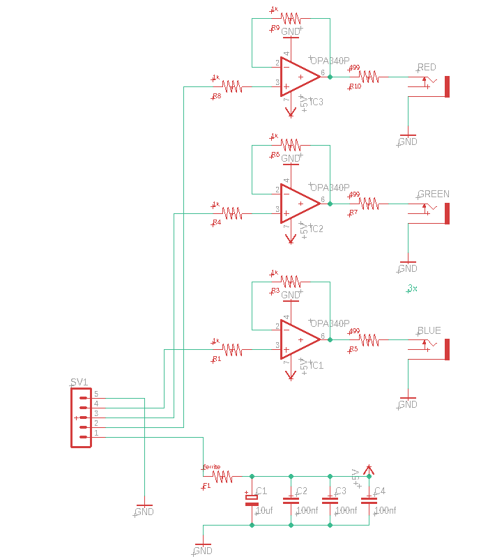
are the opamps OPA340?
I seem to recall that they are different opamps. maybe I am mistaken
#17 — rempesm · 2020-10-28
Yep!
lzxindustries/lzxdocs/blob/master/3trinsRGB+ RGB Output Expander/3trinsRGB+1c RGB Output Expander BOM.csv
Line Item,Quantity,Reference Designators,Manufacturer,Manufacturer P/N,Vendor,Vendor P/N,Description,Value,Package,Part Type,Assembly Location
1,1,-,LZX Industries,LZX-3TA-PCB,LZX Industries,LZX-3TA-PCB,LZX Industries 3trinsRGB+1c RGB Output Expander PCB,-,-,Fabricated,-
2,3,"C2, C3, C4",Vishay / Sprague,1C10Z5U104M050B,Mouser,75-1C10Z5U104M050B,Multilayer Ceramic Capacitors MLCC - Leaded 0.1uF 50volts Z5U 20% 2.5mm L/S,0.1 u,-,Through Hole,PCB Top
3,1,C1,Panasonic,ECE-A1VKS100,Mouser,667-ECE-A1VKS100,Aluminum Electrolytic Capacitors - Leaded 10UF 35V KS RADIAL,10 u,-,Through Hole,PCB Top
4,1,L1,Fair-Rite,2743001111,Mouser,623-2743001111,"EMI Filter Beads, Chips & Arrays 43 BEAD ON LEAD Z=68 OHM @ 100MHz",-,-,Through Hole,PCB Top
5,3,"R3, R8, R13",KOA Speer,MF1/4DCT52R4990F,Mouser,660-MF1/4DCT52R4990F,Metal Film Resistors - Through Hole 1/4W 499 ohm 1% 500 OHM 1%,499R,-,Through Hole,PCB Top
6,6,"R2, R4, R7, R9, R12, R14",KOA Speer,MF1/4DCT52R1001F,Mouser,660-MF1/4DCT52R1001F,Metal Film Resistors - Through Hole 1Kohms 1% 100PPM,1K,-,Through Hole,PCB Top
7,3,"J1, J2, J3",-,-,Thonk,MECH_JK_PJ302M,"Right angled 3.5mm Jack Sockets w/Knurled Nuts, No Washers",-,-,Through Hole,PCB Top
8,3,"U1, U2, U3",Texas Instruments,OPA340PA,Mouser,595-OPA340PA,Operational Amplifiers - Op Amps Single-Supply Rail-to-Rail,-,DIP8,Through Hole,PCB Top
If you rig up a Eurorack power connector, you could run the 3trins off of the +12V rail and then route the +/-12V rails to this expander so you could use LM6172s instead. I’ve run my 3trins off of a Eurorack supply for years and it’s been fine.
#18 — reverselandfill · 2020-11-18
Basic idea. some space on the panel, so maybe something can be added.
like mentioned above.
the things @rempesm posted sound useful, but I don’t have my 3trins here, so I can’t test this now.
in about a month I’m back in NL, so then I do some tests.
the connections to the Trins can be MTA with this pinout header. maybe I move it a bit
#19 — rempesm · 2020-11-18
I’m a fan of the mods I listed above but if this is wired up to the header by the AD724 on the 3trins, I wonder if it would make more sense to include the S-Video output and a second buffered composite output. Less clunky wiring, you get one cleaner output and an easy way to have one composite output for a preview monitor and save the one on the 3trins for easy feedback with a super short RCA cable.
#20 — Fox · 2020-11-18
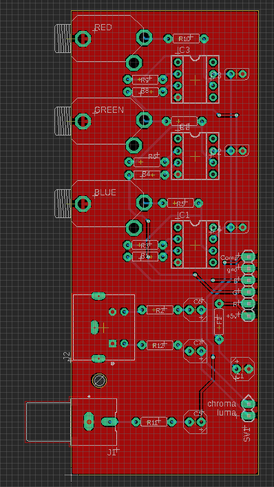
If you’re using OPA340’s, I think your positive and negative power pins are swapped.
#21 — reverselandfill · 2020-11-18
I’ll check this, thanks!
#22 — reverselandfill · 2020-11-18
you were correct. I am so used to separate power pins that this threw me off.
the power pins rotated as I mirrored the part
#23 — jsonpayload · 2021-02-01
@reverselandfill Count me in for one of these!
#24 — reverselandfill · 2021-02-01
I’m quite busy with other projects, but I’ll try to test the MODS and see if I can order these soon
#25 — blabberbytes · 2021-06-08
Would like one of these!
#26 — Fallinggirl · 2021-06-08
I’d like one too

Please
#27 — delray · 2021-06-15
+1 here too please
#28 — reverselandfill · 2021-06-16
So this would be needed for S-Video?
What sockets do you use? (pcb mount 4pin Mini DIN). something like this? 161-2204 Mouser
And the 2nd Composite output. does it need the cap & resistor or is that already covered in the 3trins somewhere?
Those 4066 horizontal / vertical range mods sound good too. I might add those as well (after some testing of coarse!)
I’ll keep the pcb with the OPA340, so that people without Eurorack can use this pcb too.
#29 — reverselandfill · 2021-06-23
I have to make some measurements for the rightangled mini-din connector, and I’ll add a support for that connector.
#30 — rempesm · 2021-06-24
Yes, your S-Video output looks correct now (I think you had the caps and resistor flipped in the last one).
Composite out also looks right and appears like you tested it to be okay too.
Let me know if you need any documentation on the 4066 mod. I would also highly suggest adding the Luma CV input for external composite video. I think it’s just a resistor to one of the points near that pot but I’d have to dig to find it. Would probably be prudent to have diode clamps to prevent over voltages, though.
Great work!
#31 — reverselandfill · 2021-06-24
For the 4066 mod, I think I make another module. something like a collector module of cool mods
(but those that are a bit more complicated to solder to the 3trinsRGB board)this lzx adapter & S-Video output module is still quite easy to do, without much soldering at different locations.
The mini-din connector looks to be centered when mounted , so that would be good news.
I’m a bit unsure on the hole diameter. I think it should be around 10mm or 12mm to get the plug in smoothly. (and so that the rubber arount the plug won’t touch the panel too much)
#32 — rempesm · 2021-06-24
reverselandfill wrote:
For the 4066 mod, I think I make another module. something like a collector module of cool mods
>>>> (but those that are a bit more complicated to solder to the 3trinsRGB board)
Great idea! Even just a 5 input 4HP module (4x gate inputs through a CD4066 in parallel with the tactile switches) and CV input for Luma would be cool.
reverselandfill wrote:
The mini-din connector looks to be centered when mounted , so that would be good news.>>>> I’m a bit unsure on the hole diameter. I think it should be around 10mm or 12mm to get the plug in smoothly. (and so that the rubber arount the plug won’t touch the panel too much)
Can you cut out a square hole in the panel file and get the connector lined up flush on the PCB where they mate? That’s how it is on the Visionary CTBC and all the S-Video cables I have all mate just fine without their sleeves getting in the way.
#33 — reverselandfill · 2021-06-24
rempesm wrote:
square hole
I think so. I started making panels with KiCad recently. It is easier there
Doesn’t LZX uses those vertical mounted mini-din sockets like the CUI MD-40SV?well, it needs some good measuring !
I was looking at this part:
tme.euhttps://www.tme.eu/nl/details/tm0508a_4/mini-din-connectoren/lumberg/tm-0508-a-4/LUMBERG TM 0508 A/4 | Contact; DIN mini; vrouwelijk; PIN: 4; afgeschermd; THT; op PCB - Het produkt is verkrijgbaar in de Transfer Multisort Elektronik. Bekijk onze uitgebreide offerte.
Link: TM 0508 A/4 LUMBERG - Contact | DIN mini; vrouwelijk; PIN: 4; afgeschermd;...
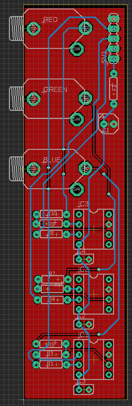
#34 — reverselandfill · 2021-11-27
I ordered a prototype pcb for this project. No panel yet, because that was the main struggle.
(Square vs round holes & positioning)
I’ll try some lasercut panels before I make one in KiCad
#35 — Fallinggirl · 2021-11-28
Can I order the 3Trins lzx plugin from you?
#36 — reverselandfill · 2021-11-28
when it is ready, you can
#37 — Fallinggirl · 2021-12-02
Please keep me updated


#38 — Fallinggirl · 2021-12-02
In fact I might buy a few from you as I am purchasing more 3Trins!
#39 — reverselandfill · 2021-12-02
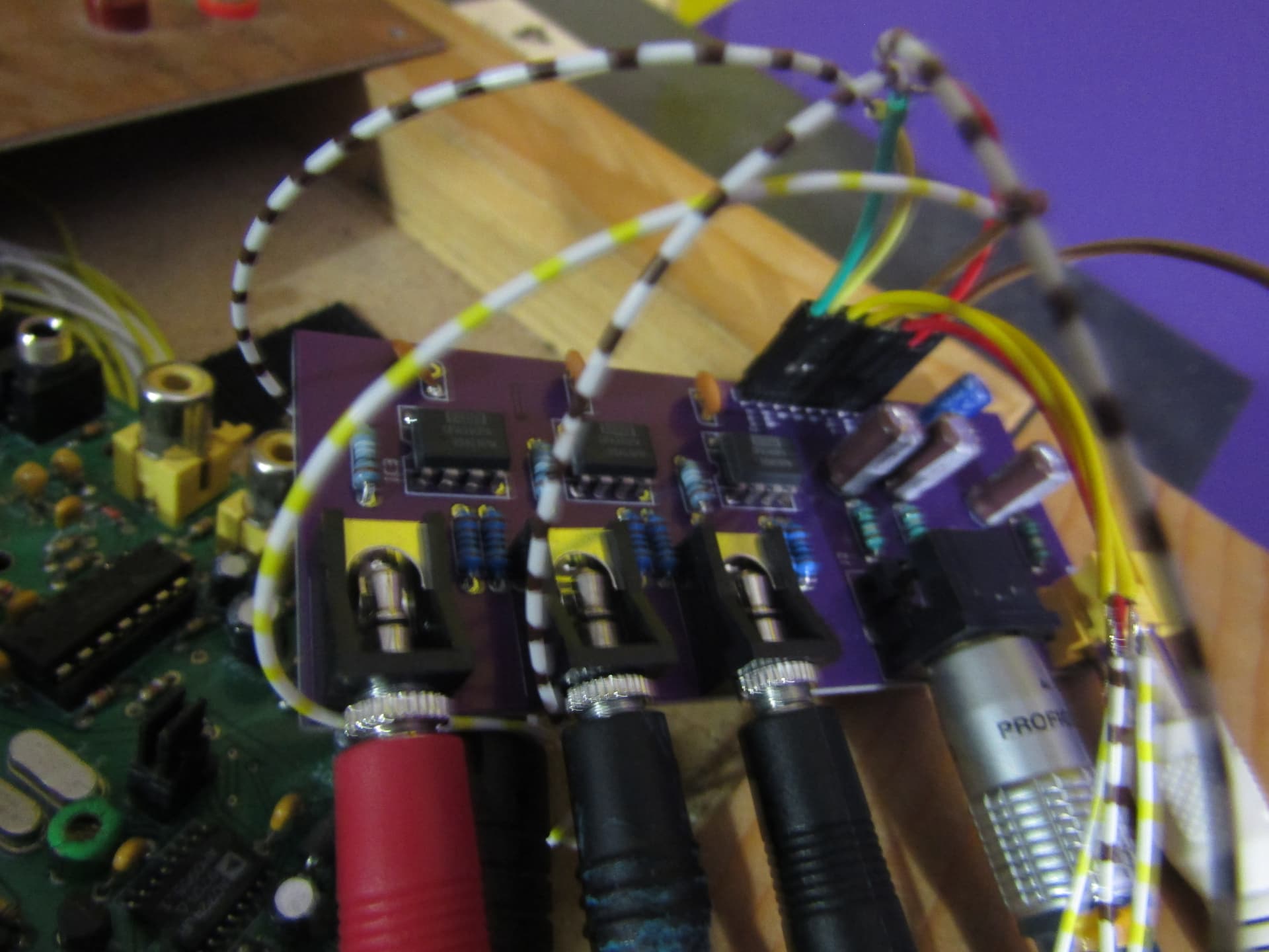
the proto pcbs are in (fast!), so I’ll be testing the pcb this week

#40 — reverselandfill · 2021-12-03
the prototype is tested and it works.
s-video output = OK
Composite output = OK
The LZX jacks can have some scrolling, this can be fixed by plugging in the composite output of the expander to the Sync input on the LZX system.
(I recall that the original plugin had the same issue)
The wire connectors can be a right-angled 8pin boxed header with a flatcable, or MTA
Maybe some other fancy solution. I’ll think about it. suggestions are still welcome
Maybe I can add another composite RCA jack to facilitate this routing, without losing that extra composite output.
I’ll also add a 5v + gnd connector for other future modules, to save some wiring.
#41 — VanTa · 2021-12-03
Flat ribbon cable maybe for the connection? With ground every second pin.
For the buffers maybe trim pots? I remember something about every unit having different voltage outputs, but not sure if that’s relevant here.
#42 — reverselandfill · 2021-12-03
The module is powerd by the 3Trins, so that does not matter, I think.
Maybe I will make 2 header options, so that the user can choose.
Personally I dislike soldering flatcable as the traces are so tiny,
but a such a connector is pretty handy
hmm
#43 — sean · 2021-12-03
reverselandfill wrote:
The LZX jacks can have some scrolling, this can be fixed by plugging in the composite output of the expander to the Sync input on the LZX system.>>>> (I recall that the original plugin had the same issue)
3trins and LZX system def need to be synced, yeah.
FWIW, I usually accomplish that in the reverse direction, syncing the 3trins to LZX output. This way an external signal can still be fed into the LZX system — and used as sync source — without having to go through the 3trins first. Generally, I am just adding the 3trins to get its oscillators, so losing the external input there isn’t an issue at all. (But this also can create some nice feedbacking options as well, processing LZX output thru 3trins.)
#44 — Fallinggirl · 2021-12-04
Please tell me when to send you the money and I’ll buy the 3Trins lzx module from you
#45 — reverselandfill · 2021-12-04
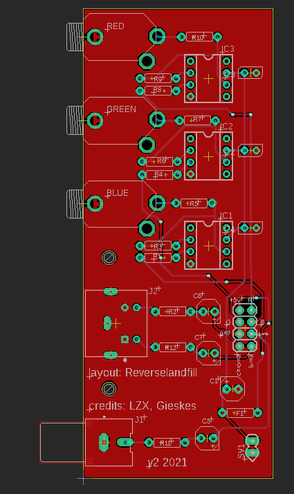
I still need to make the panel

updated pcb with 8pin IDC (right-angled) & 2pin MTA
#46 — leolodreamland · 2022-01-24
how’s it looking this side?
#47 — reverselandfill · 2022-01-24
almost done, I just have to measure out the panel (the hole position of the s-video socket) at the fablab.
The new revision of the pcb has a 8pin header and I have bought the parts for that.
this makes it possible to attach either a flatcabe with connector, or just wires if that is your preference.
I’ll try to go to the Fablab this week and then order the pcbs and panels!
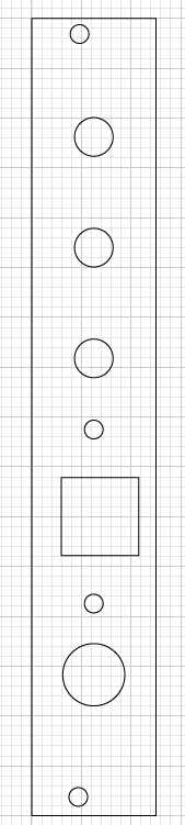
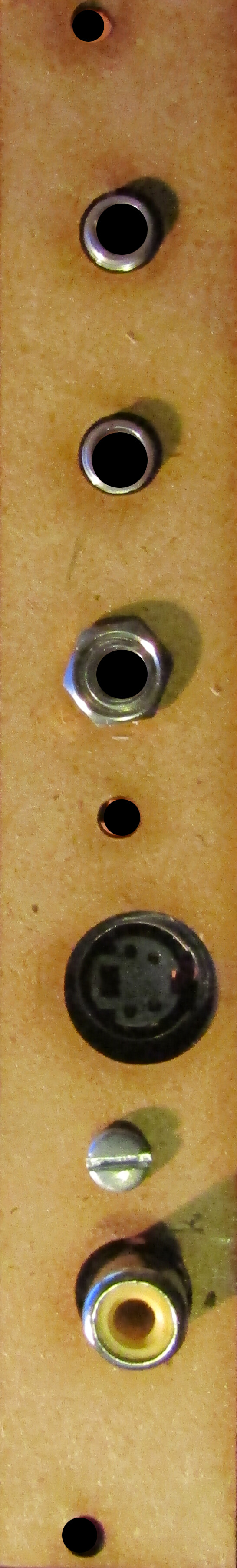
#48 — reverselandfill · 2022-01-25
after some small adjustments, the panel holes are correct.
I’m not going to use a square hole for the s-video connector after all, this round one
works just as good. I’ll go check the diameter of some more s-video cables to see if they all will fit.
#49 — reverselandfill · 2022-02-10
the next (hopefully final) prototype is ordered.
If everything is working, I will have enough for a first run.
new features:
10pin IDC connection header for flatcable connection to the 3TrinsRGB
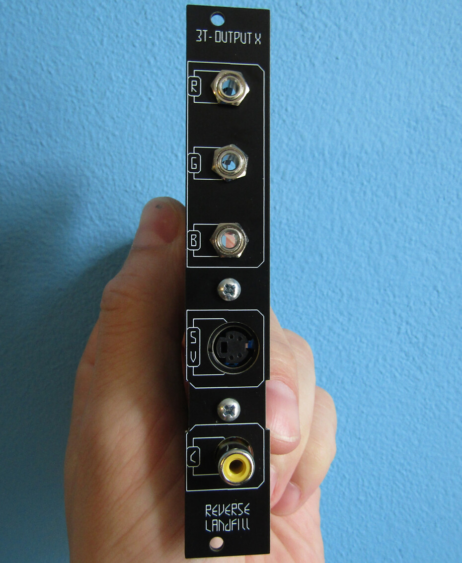
Black panel with correct hole positions
update 25-02:
pcbs are in. panel looks good. I’ll test it and then it will be released!
(can’t reply 3 times in a row)
#50 — rempesm · 2022-02-25
Very cool! Do you have photos of the new panel?
#51 — reverselandfill · 2022-02-25
here:
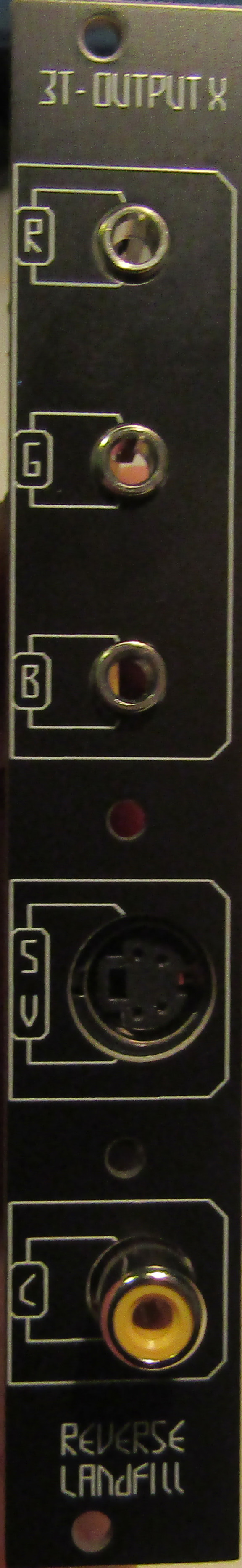
#52 — reverselandfill · 2022-03-12
I think it works fine.
but I’d like to test it with another 3TrinsRGB.
Does anyone want to help me with this?
#53 — Maytoast · 2022-03-13
I’ll love to buy a built one. Don’t mind being a test mule on this.
#54 — mjlong · 2022-03-13
I’d be happy to help, but I’m located in the US. If you can share the pcb design, I could order a board from oshpark. I should have most of the components already on hand…
#55 — VanTa · 2022-03-13
I can help with that. I also have one of the older adapters, so we can compare.
#56 — reverselandfill · 2022-03-13
@VanTa ok I’ll PM you
at the others: thanks, I appreciate your support
#57 — ojorejas · 2022-03-31
Ooh, I just saw this. I’m definitely interested in buying a built one if one is for sale!!
#58 — reverselandfill · 2022-03-31
we are testing it now. I think it will be ready soon
#59 — dr_how · 2022-04-01
Is the output from this PCB at all affected by the Scroll control on the 3trins? On the PCB directly from LZX that I built I had to constantly adjust the Scroll to maintain a steady picture (and that’s just using the oscillators, not the video input).
#60 — reverselandfill · 2022-04-01
on my test setup , when synced to the LZX (expander or 3trinsRGB out → Cadet sync in) , the image is stable.
#61 — vudoppio · 2022-04-15
Very excited about this module! Would it also work to bring routine composite signals into an LZX workflow? Will you make it available on Reverb or Etsy? Thanks!!
#62 — reverselandfill · 2022-04-19
It adds 2 extra outputs (s-video & another composite), and the LZX format RGB outs.
The LZX format outputs can be patched directly into your modules. the composite outputs are handy for routings through your modular & syncing both video synths.
it will be released on my website, Etsy and other sites, along with the updated version of the Triple Comparator.
soon!
#63 — reverselandfill · 2022-05-30
ok, I have a question to you (future users):
The output expander (3T-EXP) has a 8pin cable that connects to the 3TrinsRGB.
I have designed a helper pcb that connects to the pins on the 3trinsRGB and has a 8pin shrouded header, so that you can connect a flatcable from the 3T-EXP to the thelper pcb, and disconnect it if you please.
This cabel has to go from your eurorack case to the 3TrinsRGB.
Scenario 1:
3trinsRGB mounted in an eurorack case.
Connect the cable directly to the 3T-EXP pcb, behind the panel.
Scenario 2:
3trinsRGB situated next to an eurorack case.
Now, the flatcable should be snaked through the 3T-EXP panel in some way.
My proposal is to have a slit on the side of the panel to do just that.
The question is also, what side would be preferred? right, left, or both?

#64 — VanTa · 2022-05-30
Hmmmmm…
I guess both side slit. although somehow left feels more natural. I can’t say why though.
#65 — dr_how · 2022-05-31
I could see left side making sense because the cable will probably connect to the expander pins on the right side of the 3trinsRGB, so to prevent the cable from covering the panel on either the 3trinsRGB or the LZX adapter the slit on the panel would have to be on the left.
#66 — dr_how · 2022-05-31
Also my 3trinsRGB has already been modified with a 6 pin header to work with the original LZX adapter PCB, will that be compatible to work with the 8pin cable for this newer version?
#67 — mjlong · 2022-05-31
My vote would be for a slit on both sides, but I don’t feel particularly strongly about it. Very excited about this—thanks for the update
#68 — reverselandfill · 2022-05-31
the helper pcb has the same pin header as the LZX adapter and adds 2 extra pins.
These need to be wired or connected in some other handy way
I’ll test if I can make the connector con the helper pcb suitable for both the pinheader method and with a screwterminal blockI’ve added 2 slits on the panel (left and right) and adjusted the main pcb by moving the 8pin header next to the slit position. This way you can choose for yourself which way is best. By folding the flatcable to the back of the pcb, if will fit on the left slit.
#69 — reverselandfill · 2022-05-31
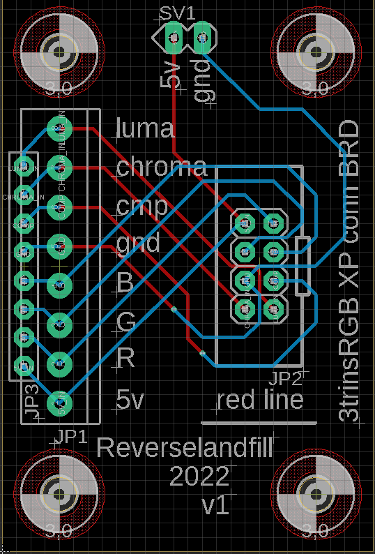
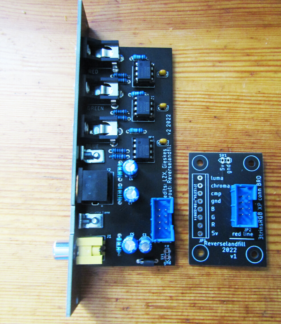
picture of the helper pcb
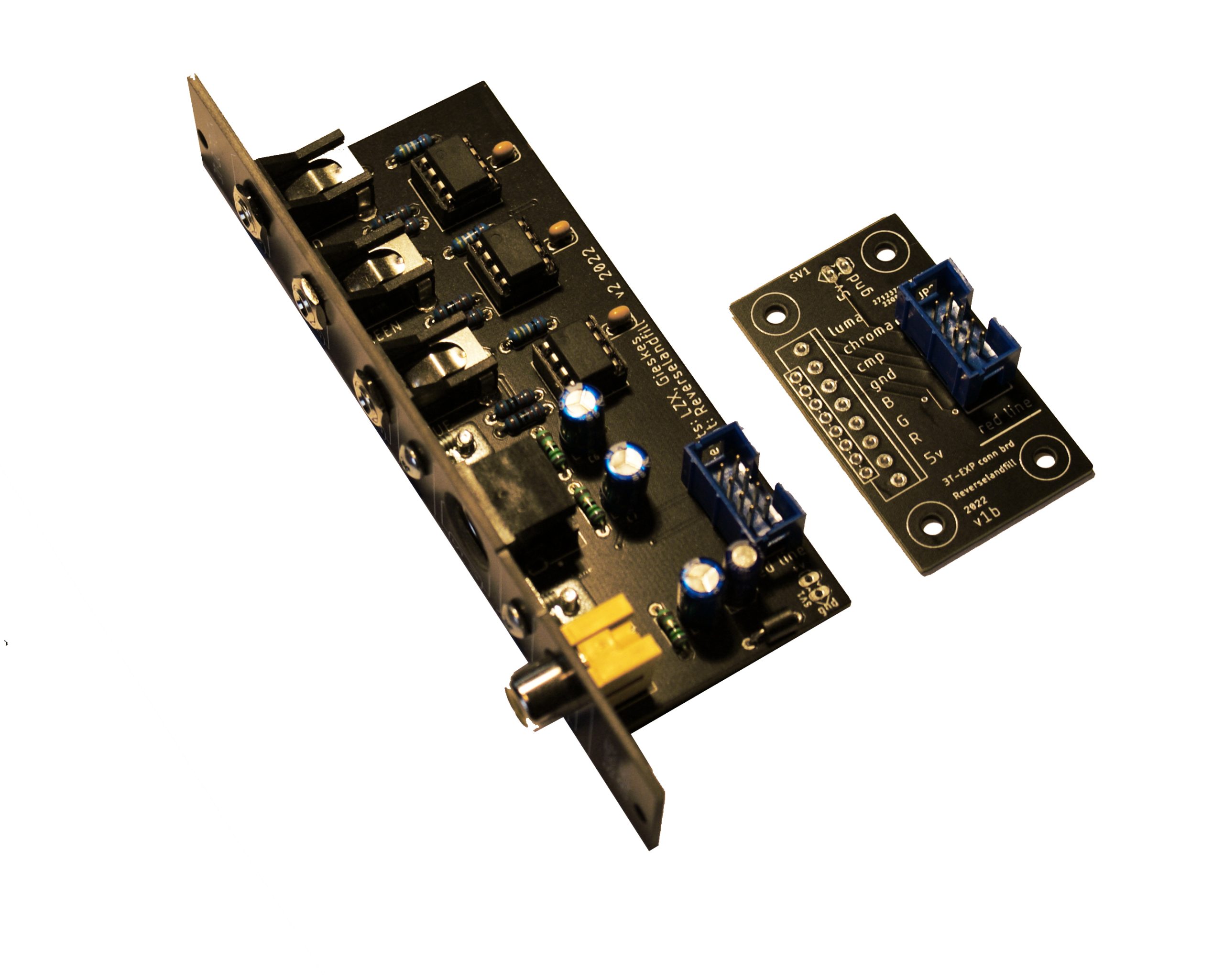
#70 — reverselandfill · 2022-07-29
new version with panel update (flatcable slots on both sides) and connector pcb
I think it is ready to go!
I’ll do a final test and then make an order thread
note: the connector pcb will get an update for people who have pinheaders on the side of their 3TrinsRGB and want to make it disconnectable.
#71 — reverselandfill · 2022-09-28
the pcb set is ready and available now. I’ll make an order thread
I still have to make a buildguide!
#72 — reverselandfill · 2022-12-02

https://www.reverselandfill.org/news/3t-output-x/Link: 3T-OUTPUT X – Reverselandfill