LZX format video Experiment board
Category: Unknown · Tags: — · Posts: 97
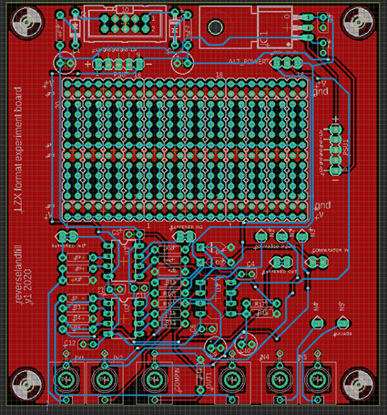
#1 — reverselandfill · 2020-10-03
I was laying out a PCB for some video experiments. While doing this I thought it might be interesting for others, too.
The idea is that you an solder a prototype and connect it easily to the headers with wires or jumpercables. The voltage sources are placed near the rails of the ‘breadboard’ , so you can connect +12v or +5v to them.
The GND rails are pre-connected.
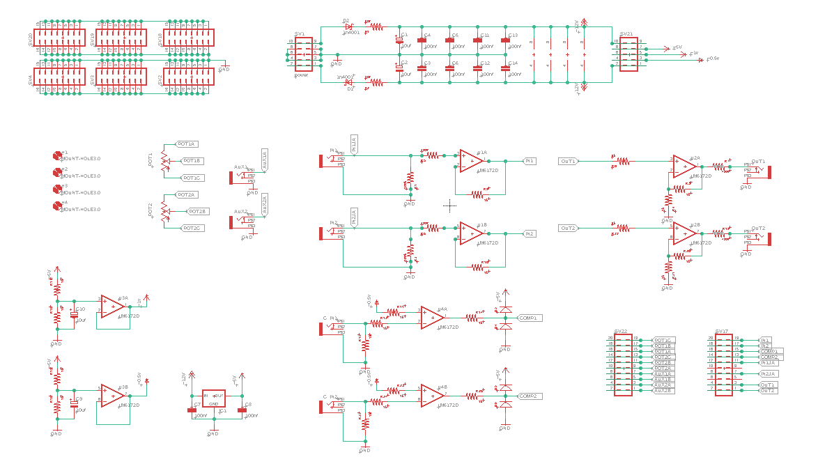
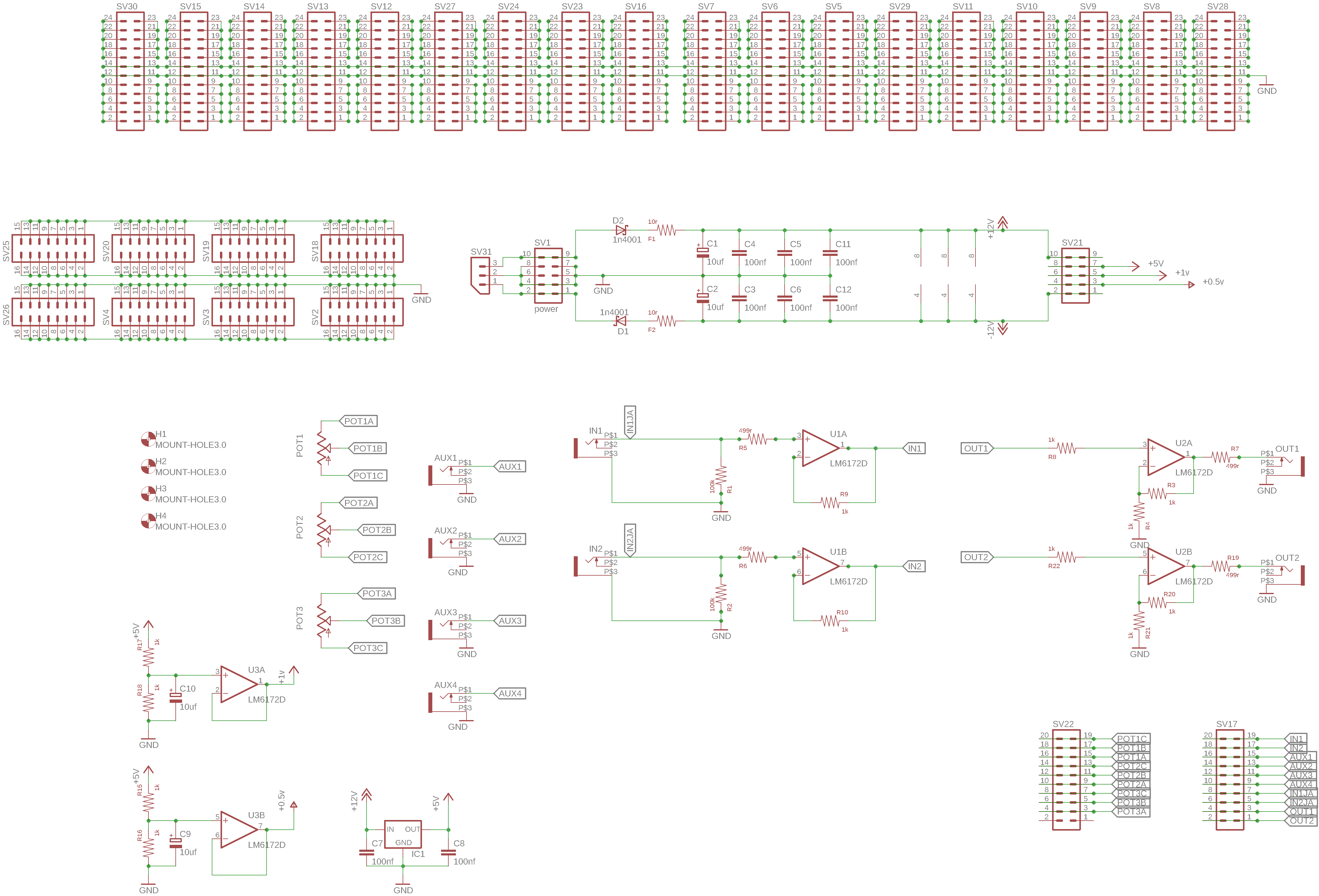
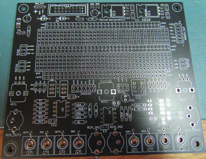
It has these features:
2x input buffer with jack
1x output buffer with jack
1x comparator with jack
2x aux jack
the outs and ins of these have pin headers.
a breadboard style solderpad grid
+0.5v, +1v, +5v, +12v, -12v, GND headers
eurorack power connector
note: the values in the schematic are not yet corrent. I’ll post bigger images later
Any suggestions on additional features?
I was thinking :
an extra comparator (negative high for CMOS reset, maybe)
some potmeters
a big connection header instead of those loose pads
negative voltage sources like -1v ?
#2 — VisibleSignals · 2020-10-03
This is an excellent idea!
Maybe a few 10K linear pots and some switches? I know they’re easy enough to add externally but it would be great to just have them there.
#3 — reverselandfill · 2020-10-03
good idea.
I might make 2 versions, a small and a big board
#4 — Robbertunist · 2020-10-03
This is a really really cool idea for anyone wanting to experiment and prototype new video synth circuits. I’d love one

Like @VisibleSignals suggested, pots & switches would be great for control. Does an actual video input (composite or S-video with decoder) make sense or would it simply be too bulky? I can easily imagine that but it’d be great if I was wrong 
#5 — reverselandfill · 2020-10-03
I think that would not fit. too much electronics envolved.
but maybe for the bigger board. if somebody can help …
#6 — Robbertunist · 2020-10-03
What if the design was a slim module, say 8 HP with two rows of knobs & jacks, with 1 or 2 10pin sockets (same as power) that connect to an external pcb that resemble a breadboard or your design. Then these finished PCBs or prototype circuits could be swapped in and out of a working system.
Damn, now I have to learn Adobe Illustrator to design this panel suggestion as my description is amateurish at best

#7 — joem · 2020-10-04
I’m interested in this! I was just wishing I had something like this the other day.
#8 — pbalj · 2020-10-04
Really like that this is happening! I had a few pcb projects like this, but never finished them. Glad something like it will be available
#9 — reverselandfill · 2020-10-04
yes, that is also an option.
I’ll make some versions of this idea and post 'm here

ideas for now:
version 1: medium size standalone pcb (like the one I posted)
version 2: big size pcb with more stuff and bigger ‘bread’
version 3: eurorack pcb&panel prototype module
version 3 has to be worked out , input & output buffers would be handy.
maybe I can make a ‘standard’ layout that allows the user to choose if an opamp is used us a buffer or comparator , with some clever part placement.
cool!
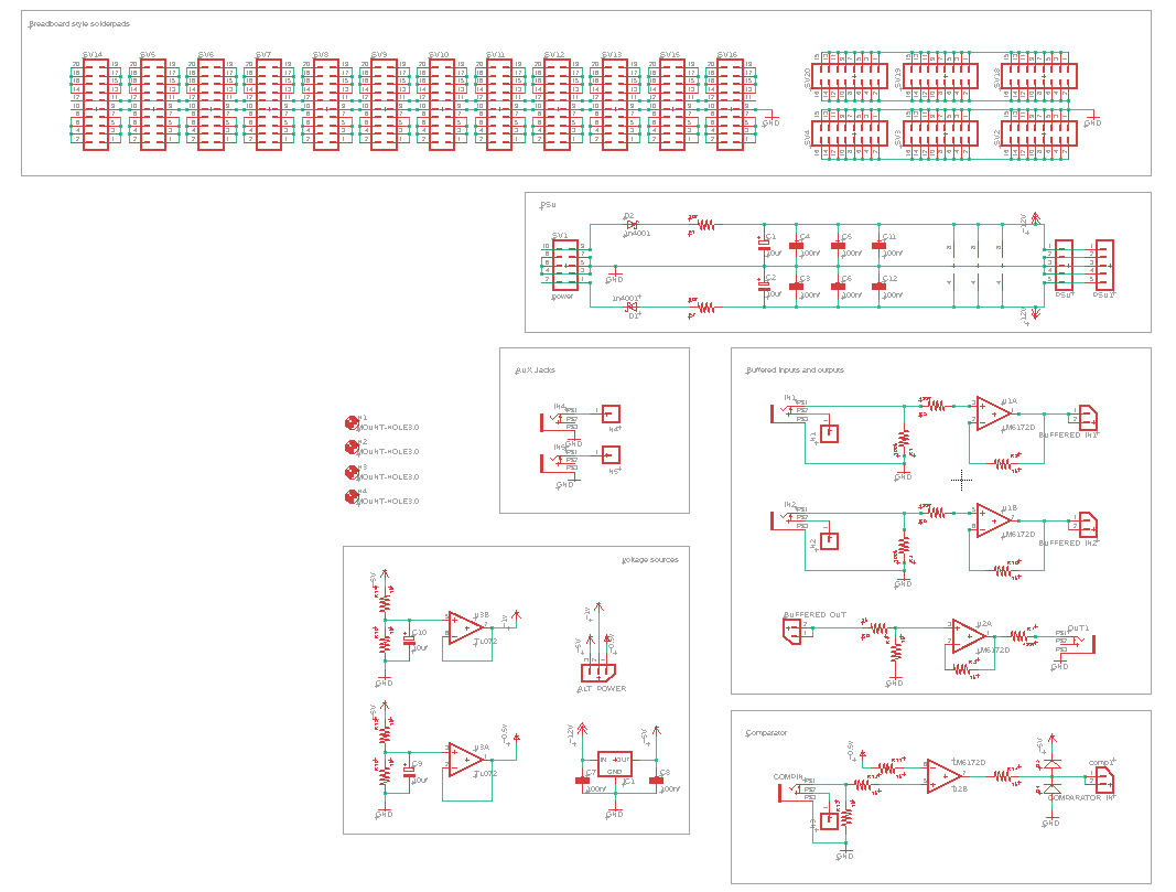
#10 — reverselandfill · 2020-10-04
thanks to all the open schematics of the Castle and Cadet series this is made possible!
#11 — reverselandfill · 2020-10-05
new features:
2x input buffer
2x output buffer
2x comparator
2x jack aux
2x potmeters
2x Pinheaders for all function connections. (I’ll add a legenda somewhrere)
The power pinheader has : +12v, +5v, +1v, +0.5v, -12v
Header access to the jacks and jack switches
It still might be useful to be able to configure the opamps to make input buffers or comparators, so that you could have a custom amount of functions for each prototype design.
I have to see if I can design a setup that is workable.
Small switches can be placed in the ‘bread area’
Any remarks?
#12 — VisibleSignals · 2020-10-05
Optional resistor to GND from the -IN of U2A/U2B and U1A/U1B so you can configure gain on the outputs/inputs.
The schematic as posted has -5V, -1V and -0.5V, which doesn’t match your description.
Is there some reason why the comparator inputs are inverted? Maybe make it jumper selectable to swap the + and - IN pins on those op-amps?
#13 — reverselandfill · 2020-10-05
Thanks! I’ll check the schematics tomorrow.
I want to make this as open ended as possible.
the 1v, 5v etc have indicator lines (those are not minus signs)- I might change this for clarity
I think I will try to make all opamp configs possible. . . just have to find a way to make it easy to operate.
as for the comparator polarity, I used the opamp setup from the Castle schematics.
@syntonie gave me a tip on how to add a composite in & output . that is interesting too
#14 — joem · 2020-10-06
Might be handy to have dual DIP8/SOIC8 footprints for the LM6172’s, since the DIP 6172’s aren’t in production any more? Though people can use those cheap converter PCBs to accomplish the same thing, so it’s not a huge deal.
(This is something I’m dealing with in my own project right now. I want to figure out how to make such a dual footprint in kicad, but I’m having too much fun with the programming aspect of my module right now to bother with that. Haha.)
#15 — VisibleSignals · 2020-10-06
LM6172IN/NOPB (DIP package) are still marked Active by TI, so still being manufactured. The old versions without the /NOPB extension (which contained lead) are EOL, so that might be the source of the confusion.
#16 — joem · 2020-10-06
Ha. I could have sworn I carefully checked that on Mouser and they said it was EOL, but I guess either I wasn’t careful or I didn’t actually check! Whoops.
#17 — VisibleSignals · 2020-10-06
Mouser has an incorrectly labelled “Product Discontinuance Notice” from 2018 which is actually a Product Continuation Notice that TI has moved manufacture of LM6172IN/NOPB from Grenock, UK to Dallas, USA
https://www.mouser.com/PCN/Texas_Instruments_PCN20180308002_20180309162016256[1].pdf
#18 — reverselandfill · 2020-10-06
yes, that what I thought.
maybe the eurorack version will be SMD , if that means I can fit it on a single pcb
#19 — reverselandfill · 2020-10-06
do you know snapeda?
it has an immense amount of footprints for most CAD layout software, including kicad, free for download (you have to make an account)
#20 — joem · 2020-10-07
I’ve heard of snapeda but never checked it out. Now my need of this dual footprint isn’t so great, but I’ll remember this for next time.
#21 — syntonie · 2020-10-13
Really cool idea, that would be useful for prototyping for sure!
About composite, the IO setup is quite straightforward (75ohm to ground with op-amp buffer for input, 2x gain op-amp with 75ohm in serie for the output), a nice addition would be a sync extractor as LM1881 or LMH1980, but depends of the space, and can also be soldered to the “veroboard” area if needed.
#22 — reverselandfill · 2020-10-15
Bastien’s composite schematic.
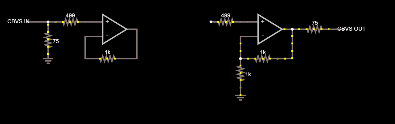
is possible in this setup:
#23 — Zifor · 2020-10-15
Additional idea: instead of a breadboard interface , why not some headers? Then we can non destructively bus various circuits using the same PCB idea you are making. Would be great for fast prototyping of a few ideas at once
#24 — reverselandfill · 2020-10-15
all the ‘breadboard’ pads are on a standard header grid, so it is up to the user to make use of that.
My main purpose is that I want to make semi permanent prototypes, where the ‘semi’ part can be the connections to certain pots and jacks and the buffer stages
all my products are open source, so you can also make your own variations.
#25 — Zifor · 2020-10-15
Thanks again for your open source work
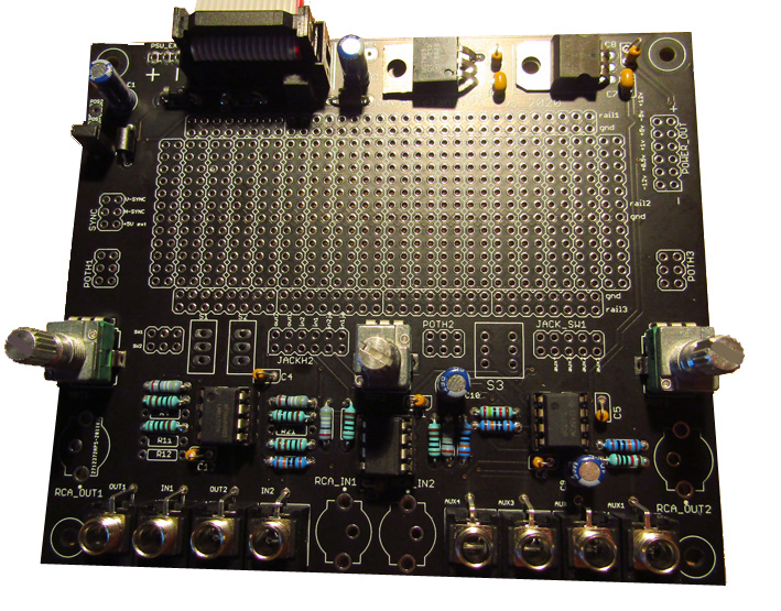
#26 — reverselandfill · 2020-10-28
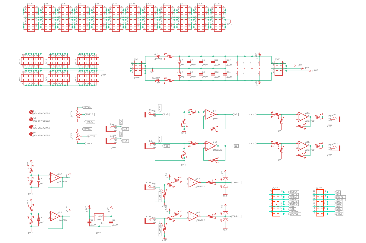
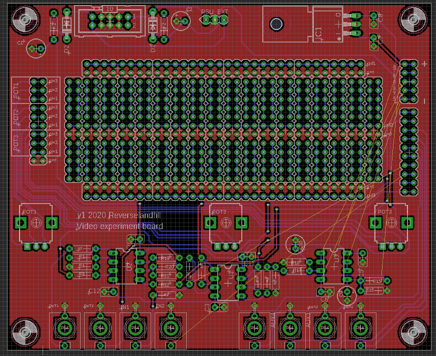
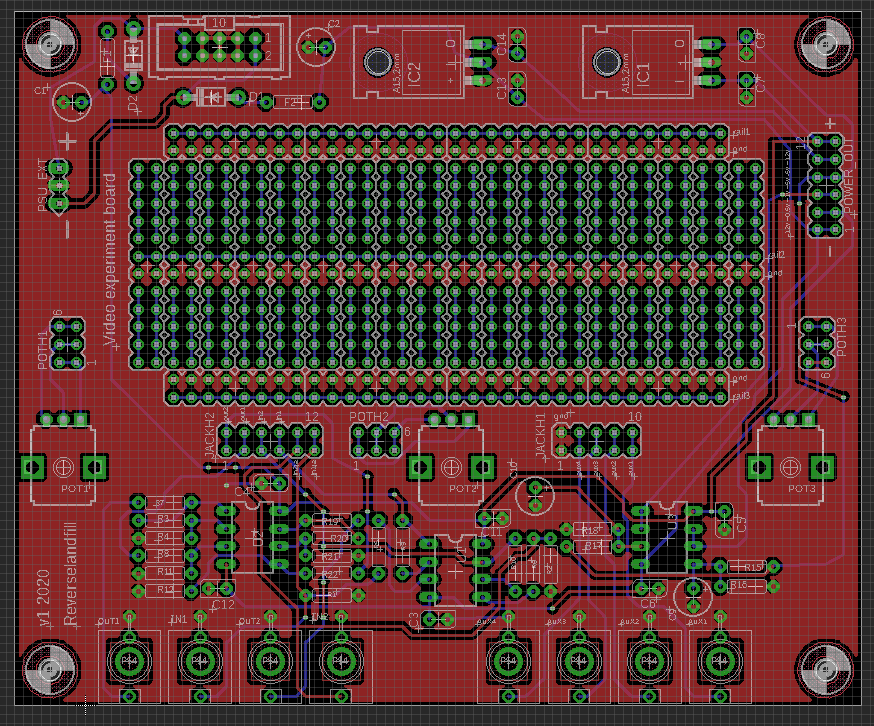
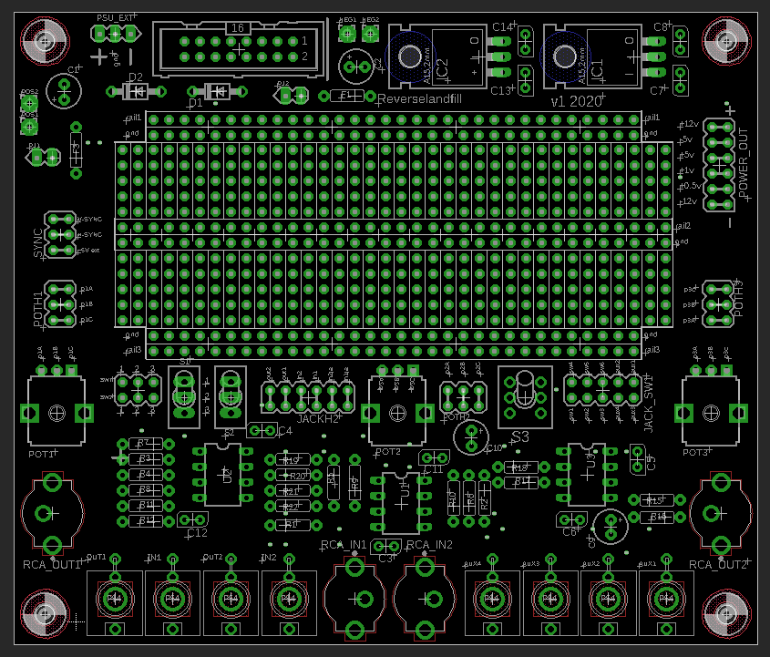
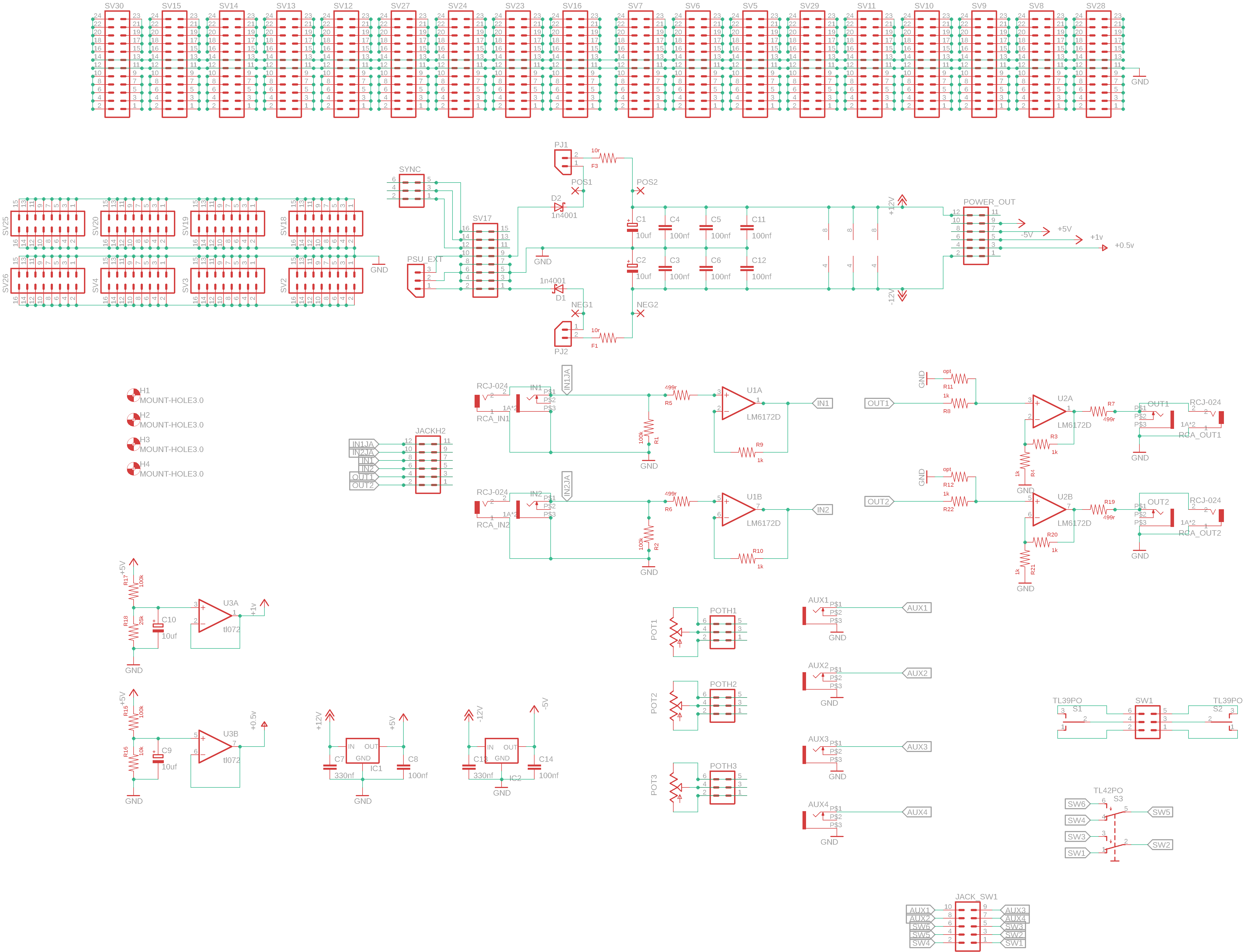
newest updated design, layout in progress. If you see any obvious flaws (schematic related) please tell me!
I’m ordering this one first, then see what features could be better for smaller versions!
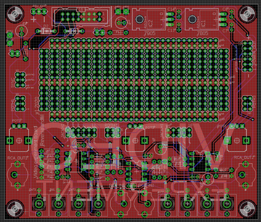
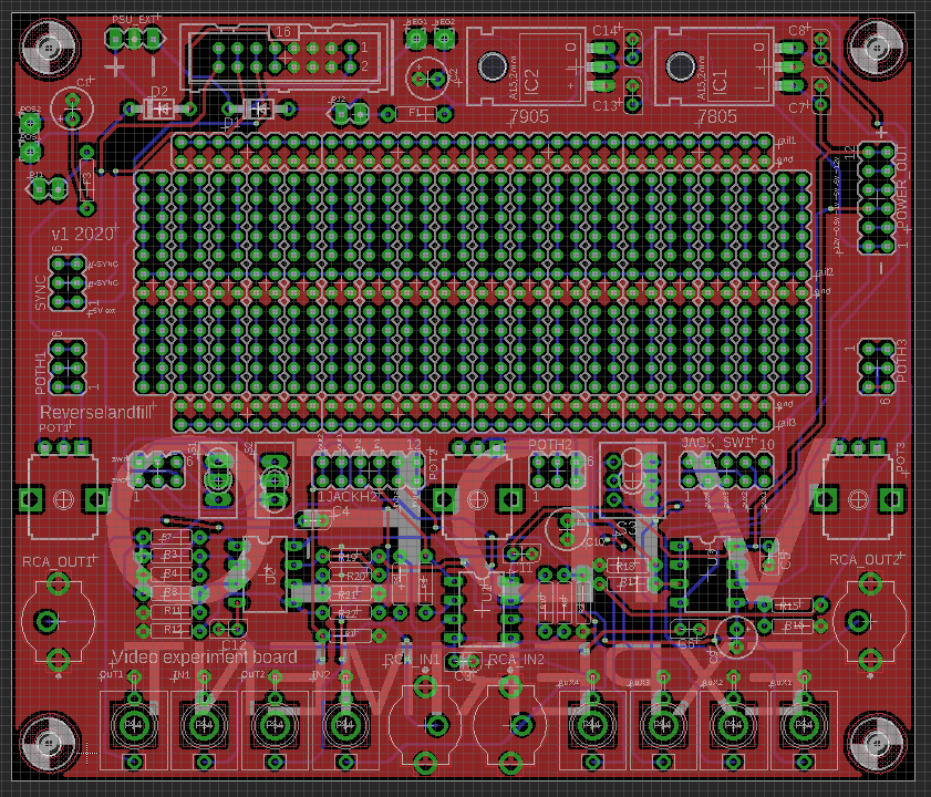
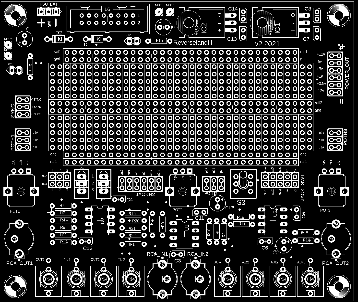
Bigger soldering area, wider pcb. power options expanded
3 aux pots, aux 4 jacks, 2x buffered video in, 2x buffered out
big schematic file:
#27 — VisibleSignals · 2020-10-28
On the ouput op-amps I suggest an optional resistor to ground from the +in pin, so it could be configured as a voltage divider if required.
All those thin parallel bottom layer traces might lead to signal crosstalk and stray capacitance… maybe it would be better to try to reduce the trace lengths if you can, even if it means the connection points are distributed around the board rather than all together… Video-rate electronics can be pretty tough

Also, having -5V regulation as well as +5V would open up possibilities for some of the non-12V capable op-amps and other chips. Some of those are SMD and smaller footprint, though.
#28 — reverselandfill · 2020-10-28
thanks for the detailed tips!
I’ll try to reduce the length and parallel lines.
routing is a bit of a pain, with those headers all on one side.
-5v is a good idea, I’ll add it!
for now, I leave it at through hole. maybe with next version we can try SMD parts
I just want to start using this board as quick as possible, then see what can be updated in the future
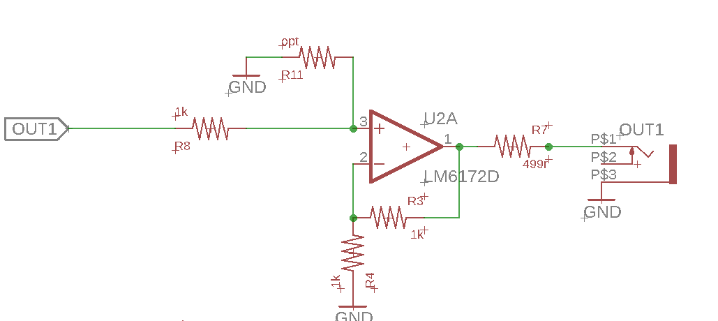
voltage divider thingy: like this? My mind if all lines now, so I can’t think…
#29 — VisibleSignals · 2020-10-28
Yes, perfect. You can do almost anything with an op-amp like that, boost or cut! (let’s not think about inverting
)The scaling formula is: OUT = IN x CUT x BOOST
Where CUT = R11 / (R8 + R11) and BOOST = R4 / (R3 + R4)
Since we normally keep R3 constant at 1K, that means the boost is mostly a factor of R4. For the cut, any reasonable middle-of-the-road values for R8 and R11 will be fine.
My advice is to just get it made up. You’ll work out what needs tweaking soon enough once you’re using it. There will always be another better version
#30 — reverselandfill · 2020-10-29
smaller headers, -5v , shuffled parts around. almost ready to go!
one thing I wanted to do is add composite RCA footprints. have to look for those. does anyone has the right angled ones LZX uses on the Cadet?
maybe I will exchange the 10pin powerheader for a 16pin, to have sync lines…
#31 — Robbertunist · 2020-10-29
RCJ-044 Footprint
https://www.cuidevices.com/product/resource/pcbfootprint/rcj-044
#32 — VisibleSignals · 2020-10-29
Heh, you just beat me to it
#33 — Robbertunist · 2020-10-29
I was expecting the same to happen to me

Got to love the Internet for speed of info gathering.
This will be the limit of my ability to help with technical stuff but every little bit counts I guess.
#34 — VisibleSignals · 2020-10-29
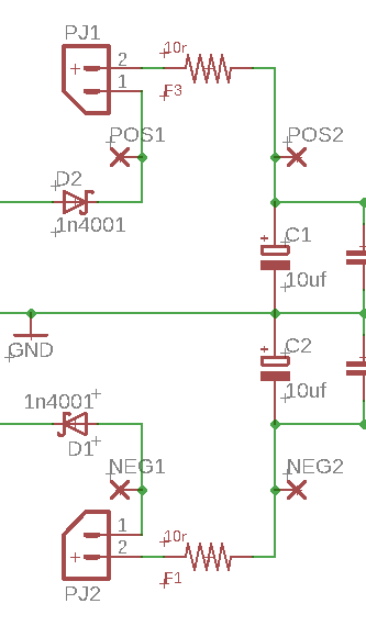
I thought of something else! Might be a bit left-field but how about a break in each of the incoming power lines from the euro power connector, with a pin header you normally jumper across but which you can remove when you want to use your multimeter leads to measure power consumption? If you don’t want it you can just solder a wire across it.
#35 — VisibleSignals · 2020-10-29
There are plenty of non-right angled RCA connectors you could use if you wanted to keep consistency with your other sockets and pots, by the way.
#36 — reverselandfill · 2020-10-29
yes, that is a good idea. still need one of those - a RCA vertical footprint, like the one on @syntonie CBV001 (I have one that I used on the syncbus, but it is a bit uncommon I think)
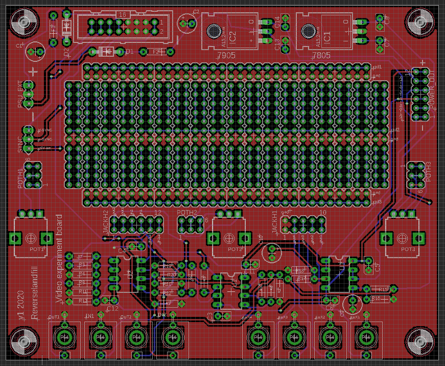
updated version with sync
#37 — reverselandfill · 2020-10-29
I have to see what I do with that. some jumper solution maybe
or the ferrites
#38 — VisibleSignals · 2020-10-29
Using the ferrites is a great idea! Good thinking
#39 — reverselandfill · 2020-10-29
this looks workable. jumper inserted = power goes through ferrite, no jumper = you can measure the mA use via the pos1 & pos2 pads, neg1 & neg2 pads for the negative side.
#40 — reverselandfill · 2020-10-29
with RCA connectors
#41 — LauLindqvist · 2020-10-30
Late to the party here. I think this is a great idea! Have tinkered with a kind of plugin header for my own breadboarding, but it didnt fell out that good…
One thing i would like added is a few toggle switch headers, since these are always a PIA to fit on breadboards. Preferably 2 standard SPDT, and one DPDT. And if people dont need those in their designs, they can leave them not soldered
/Lau
#42 — reverselandfill · 2020-10-30
2x spdt 1x dpdt . these are mini switches. else it did not fit
#43 — Robbertunist · 2020-10-30
Ahh, the 3 mini switches are located to the left of pots 1&2. I hadn’t noticed them until your suggestion @LauLindqvist, thanks for that
#44 — reverselandfill · 2020-10-30
I will have to make a big manual for this project, with all possibilities packed in like this.
Already I can see an update with a more systematic layout / graphics on top of it all.
I’m not fond of so much text on the pcb. maybe I’ll do something about this…
#45 — Robbertunist · 2020-10-30
Make an online version updateable by users, that way we can help you document it
#46 — VisibleSignals · 2020-10-30
Thanks for this Martijn - you’ve done a great job!
#47 — reverselandfill · 2020-11-02
ordering the boards now…
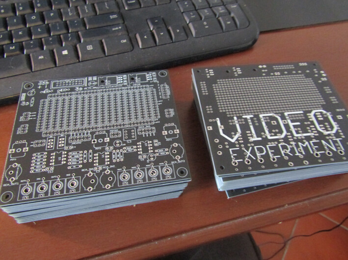
#48 — reverselandfill · 2020-11-12
The pcbs are in! I’ll test them, then make an order thread
#49 — wednesdayayay · 2020-11-12
wow this is going to be neat!
and boards arriving in 9 days seems much more reasonable than I was always assuming on PCB turnaround time
#50 — reverselandfill · 2020-11-12
fast delivery costs more, but I like fast
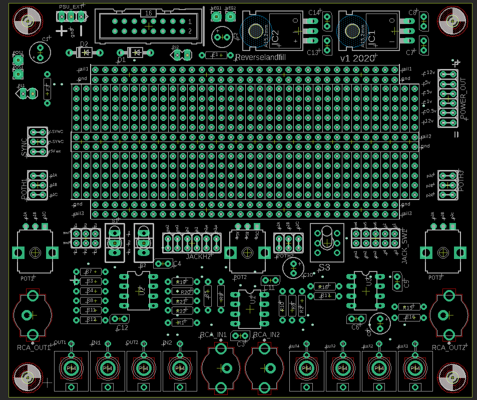
the only mistakes I can see for now is that I forgot the middle rails markings. but that is not really a problem.
I have 50x pcbs for this run
#51 — Robbertunist · 2020-11-12
50x! You’re “all in” Martijn

Thanks for posting the news & photo, it’s really great to see
I’ll attempt another group buy here in Berlin. Just stumbled across another LZX user (Vidiot to be exact) on Fakehook 2 days ago who’s also based here.
#52 — reverselandfill · 2020-11-12
I’m going to make them “cheap”, with 5x or 10x pack discount, so you can experiment a lot!
I needed at least 10 for myself, if not more
#53 — reverselandfill · 2020-11-14
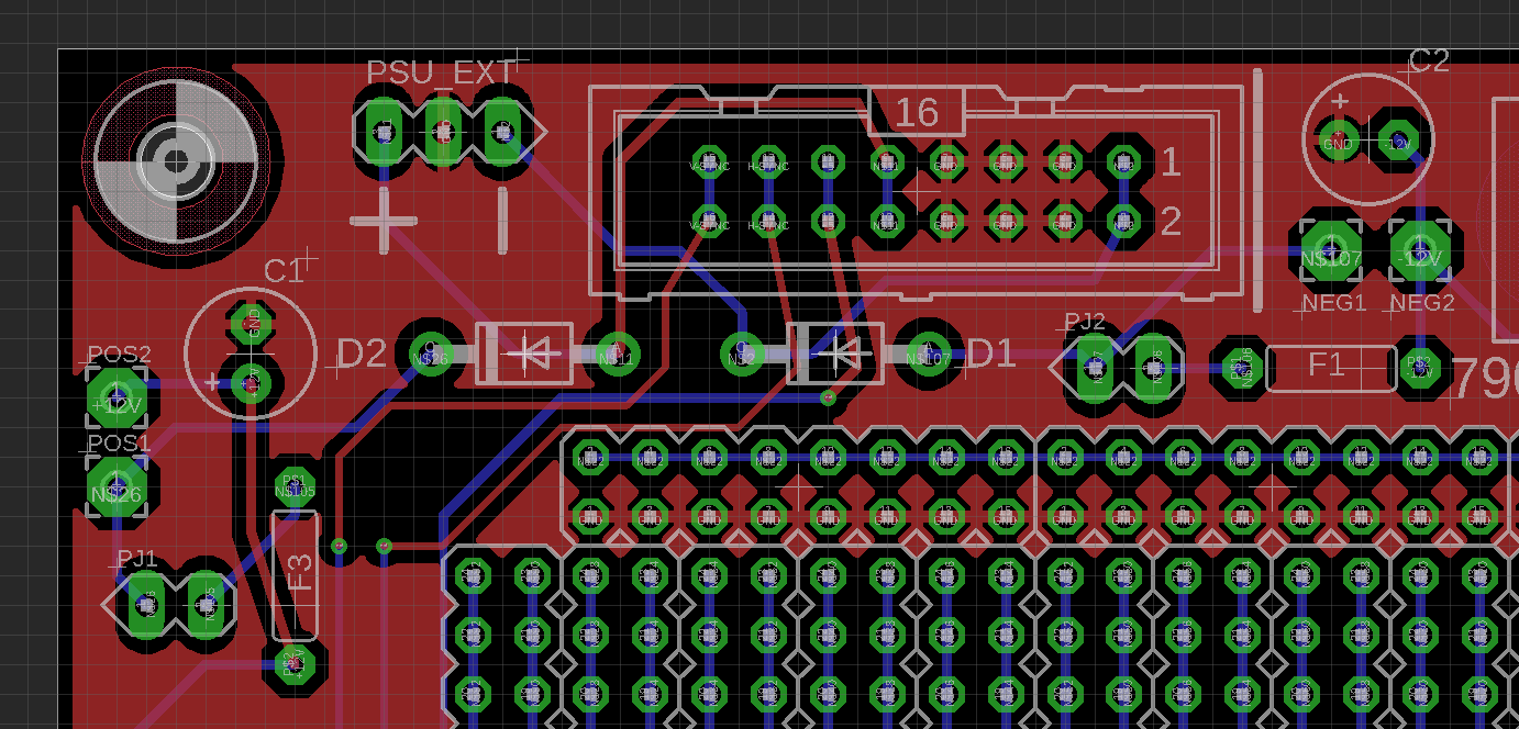
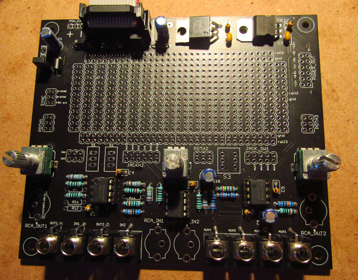
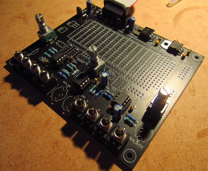
First test = OK. voltages are all correct. pots, jack and header connections work.
next up: …an experiment!
#54 — Robbertunist · 2020-11-15
@VanTa, @destroythings, @horacio2222, @cyberboy666
Any of ye interested in getting some of these from Martijn? His design looks very close to ready if not already done.
#55 — joem · 2020-11-15
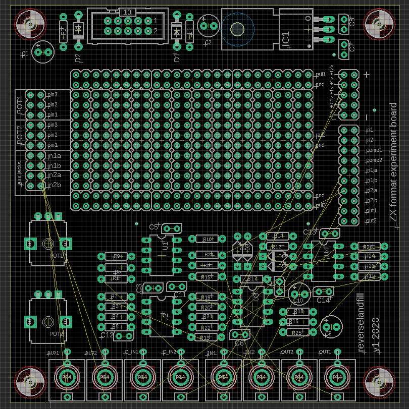
I have a few hopefully-helpful silkscreen comments/suggestions, mostly in the spirit of putting as much info on the silkscreen as possible so someone using it never has to guess about a header or refer back to documentation to make sure about something…
-
It’d be nice if the silkscreen explicitly showed the connections and rails unambiguously for the breadboard area. As it is now, the silkscreen makes me think that every two rows are connected (like a 2x5 or 2x6 header), instead of just single rows connected (like a 1x5 or 1x6 header). Also the middle rails aren’t obvious. And the silkscreen makes me think the side rails might be separated every 8 holes.
-
Similarly, it’d be nice if the pot headers showed which pins are connected. One can assume that it’s 3 groups of 2 connected pins, but it’d be nice to be explicit.
-
It’d be nice if the jack headers were labeled a bit more, since from the last pcb layout you posted it looks like the two rows of holes are not simply doubled up as they are for the pot headers. I presume one row is jack and one row is jackswitch, but if that is the case, the silkscreen doesn’t seem to indicate which is which as far as I can tell.
-
If you rotate the labels for the Power Out holes you can probably fit them next the their respective pins, which I think would be an improvement.
-
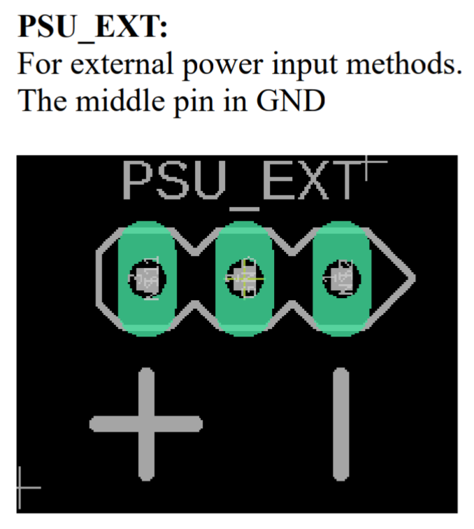
It’d be nice if the PSU EXT headers had the middle pin labeled too. I presume it’s ground?
I know this isn’t the best timing, since you already ordered and received the first batch. Sorry. But maybe consider these suggestions for the next batch? (I assume you’re going to sell a bunch of these – I know I want several, even if you don’t implement these silkscreen suggestions!)
#56 — reverselandfill · 2020-11-15
tips for the next version
most things I figured out myself too.
Sometimes you get too focused on certain things, then regret it after you have send the files.
I’ll make an overlay as helpfile
#57 — reverselandfill · 2020-11-19
next version update.
breadboard area now has clear markings (on the top and bottom side of the pcb)
pot, switch and jack markings are more clear
power out markings are better
ext PSU has gnd label
connected header pads have lines
suggestions welcome!
#58 — VisibleSignals · 2020-11-19
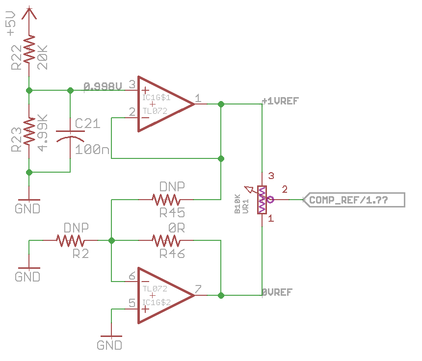
Regarding the POWER_OUT header: I can see the +5V and -5V regulators, but where are the +1V and +0.5V voltage reference circuits located on the board?
#59 — Fox · 2020-11-19
The schematic above shows them coming out of U3. The resistor values (R15-18) are all listed as 1K, so they may not have been calculated at the time of posting.
U3 should probably be a TL072 if they are used as unity gain buffers without a negative feedback resistor.
#60 — VisibleSignals · 2020-11-19
Ah! I see. I was expecting to find a TL431 like the Cadet RGB encoder has, to make sure those voltages are stable even if the power rails aren’t so good. Here’s a circuit I use for reference voltages:
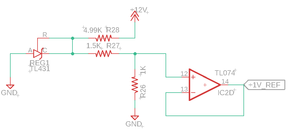
The ratio of R26 : (R26+R27) sets the voltage divide from the TL431’s +2.5V output. To get +0.5V I would use a second voltage divider (1K / 1K) from the +1V_REF into a second op-amp.
#61 — Fox · 2020-11-20
I find myself using a TL431 only if I don’t already have a 7805. There are special, more sensitive cases though. Such as the voltage controlled current source like you can see in the ramp generator or vco.
#62 — VisibleSignals · 2020-11-20
Ah, yes - you’re quite correct. No need to use a TL431 because of the 7805.
#63 — Fox · 2020-11-20
Thats just my opinion though and I probably have the noisiest power supply possible! A precision voltage reference would benefit any design if you really need one. I’m not trying to say the opinion is absolute.
#64 — VisibleSignals · 2020-11-20
Of course, but what you said makes complete sense. The TL431 isn’t usually needed for steady reference voltages rails, since the 7805 is already fulfilling that role. But if there is a requirement for one (like the VCO constant current source you mention) then it can be added on the main veroboard section. It’s about balancing how often something will be needed (in this case not very often) against how much space it will take up to include it on every board.
#65 — reverselandfill · 2020-11-20
the power out header on the right has these voltages:
-12
+0.5
+1
+5
-5
+12
the schematic uses a tl072 for the voltage divider block
I’ll draw in the correct values in the schematic for you, this will clarify it.
I tested all voltage levels, they are correct.
#66 — reverselandfill · 2020-11-20
version 2 schematic. (high res file)
ps: is there any need for -0.5v or -1v? I did not add this. maybe you can do it yourself with the provided -5v . I haven’t seen it much in the Castle / Cadet schematics.
#67 — rempesm · 2020-11-20
-1V would be good for invert+offset to keep it within 0-1V like in @syntonie’s VU004.
#68 — VisibleSignals · 2020-11-20
My opinion is no - it’s not that commonly used, and when it is needed it’s very easy to derive from +1V.
Having +1V for a basic starting point for other voltages is worthwhile, and +0.5V is the second-most useful because it’s a building-block for logic circuits (like Castles).
That said, given you can just change the resistors to adjust the voltage it might make sense to have one op-amp configured as a positive rail and the other as a negative? Or if you want a deluxe version then make it configurable so each rail can be positive or negative depending on which resistors are populated. I hope that makes sense - if not let me know and I’ll draw up a schematic.
#69 — reverselandfill · 2020-11-20
please show me. I have made a sim , but I’m unsure if I’m doing it correctly
#70 — VisibleSignals · 2020-11-20
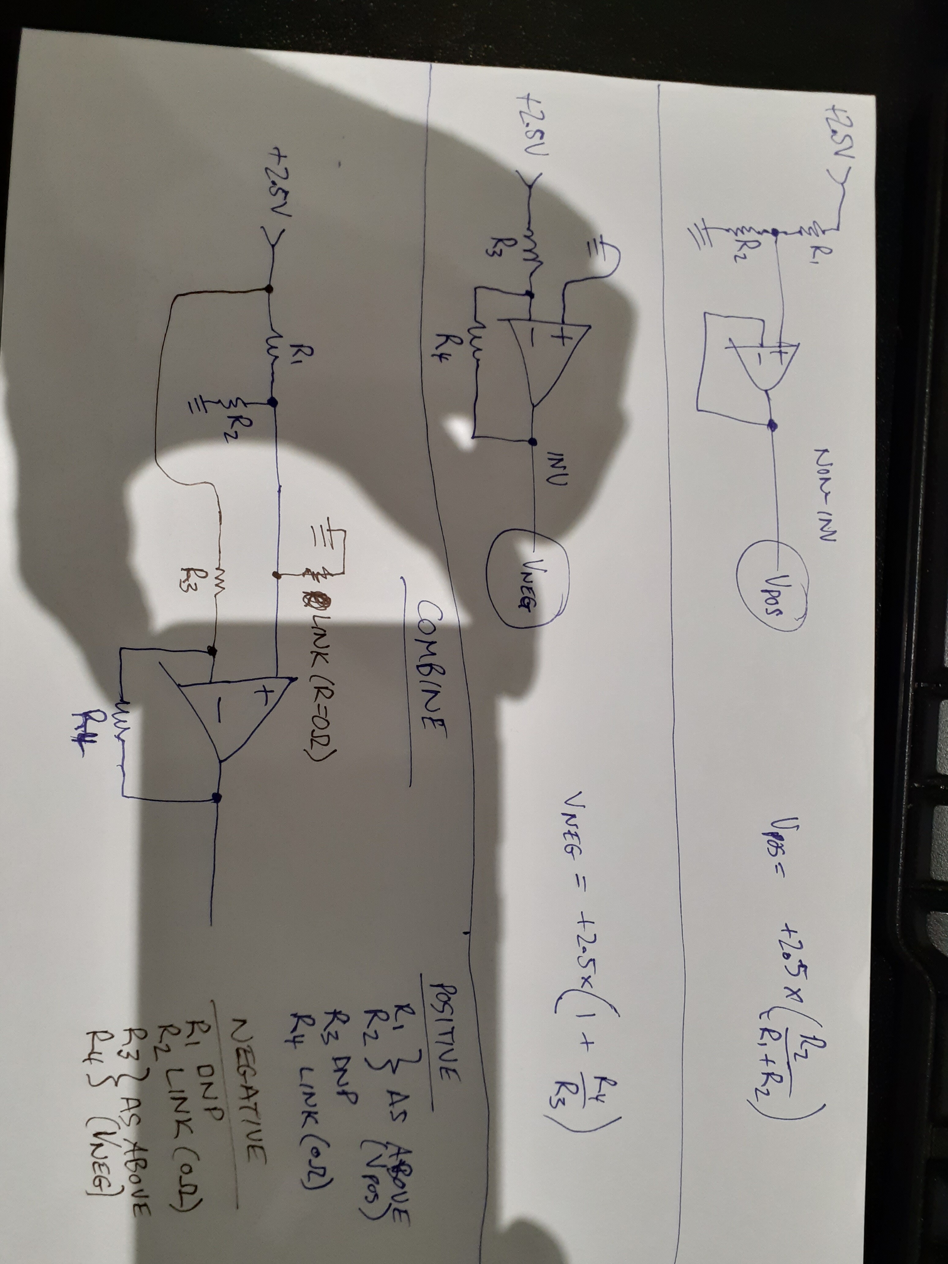
That’s a funny photo, my hand is eating my phone
Sorry that is laid out for a TL431 generating the +2.5V. But it should work just fine with +5V, just change the formulas.
#71 — Robbertunist · 2020-11-20
What kind of circuit would require the “combined” arrangement in your diagram @VisibleSignals? I’m a complete electrical noob so I’ve no idea when the inverted & non-inverted would be used either. Just really curious.
#72 — Fox · 2020-11-20
The “combined” version offers both configurations on one pcb layout. You will only populate one configuration at once. Choose either “Positive” or “Negative” configuration.
Here is the schematic I have used for the threshold pot on my RGB Selector WIP. For the purposes of the board, I have it set up for the pot to sweep from 0 to +1v, but by swapping some of the resistors, you can make it do anything from ‘-5v to +5v’, ‘-2.5 to +2.5v’ and most anything in between.
#73 — Robbertunist · 2020-11-20
Thanks @Fox
It’s cool to see a real world example.
#74 — VisibleSignals · 2020-11-21
The Vneg formula should have a minus sign sorry. It was very late when I scrawled that down, and of course there is a limitation I should have pointed out: the magnitude of the negative rail cannot be less than the 2.5V (or 5V) reference input, because the inverting op-amp in that circuit cannot have (inverted) gain < 1. If you add another resistor to ground from the IN- on the op-amp it should be possible to get lower voltages but the formula is more complicated so probably just need to fiddle with resistors to work it out.
I highly recommend trying this all out on a breadboard (or a simulator) to learn more about it! These sorts of op-amp building block circuits are important to understand and a first step towards designing your own modules. https://www.electronics-tutorials.ws/opamp/opamp_2.html
#75 — Robbertunist · 2020-11-21
Cheers Adrian for the correction & especially the tips & link. I’ll definitely try breadboarding it in the coming weeks. Winter, the time for learning & focused attention

#76 — reverselandfill · 2020-12-04
I ordered v2 of these boards.
updates: breadboard markings on both sides + some small things
#77 — VisibleSignals · 2020-12-04
I’ll grab a few of these as well, always love your work! But will batch up a bunch of your stuff for combined postage: just assume a 3-monthly “one of everything” order from me
#78 — reverselandfill · 2020-12-04
ha! the same with your stuff
more economic and ecologically
#79 — reverselandfill · 2020-12-18
version 2 (although I forgot to update the version number on the pcb…oops)
the solder area markings are printed on both sides of the pcb.
all pads are labeled better now.
#80 — rempesm · 2020-12-18
I made one of the V1 boards I picked up into a little breadboard. Handy for quickly sketching/testing small circuit blocks.
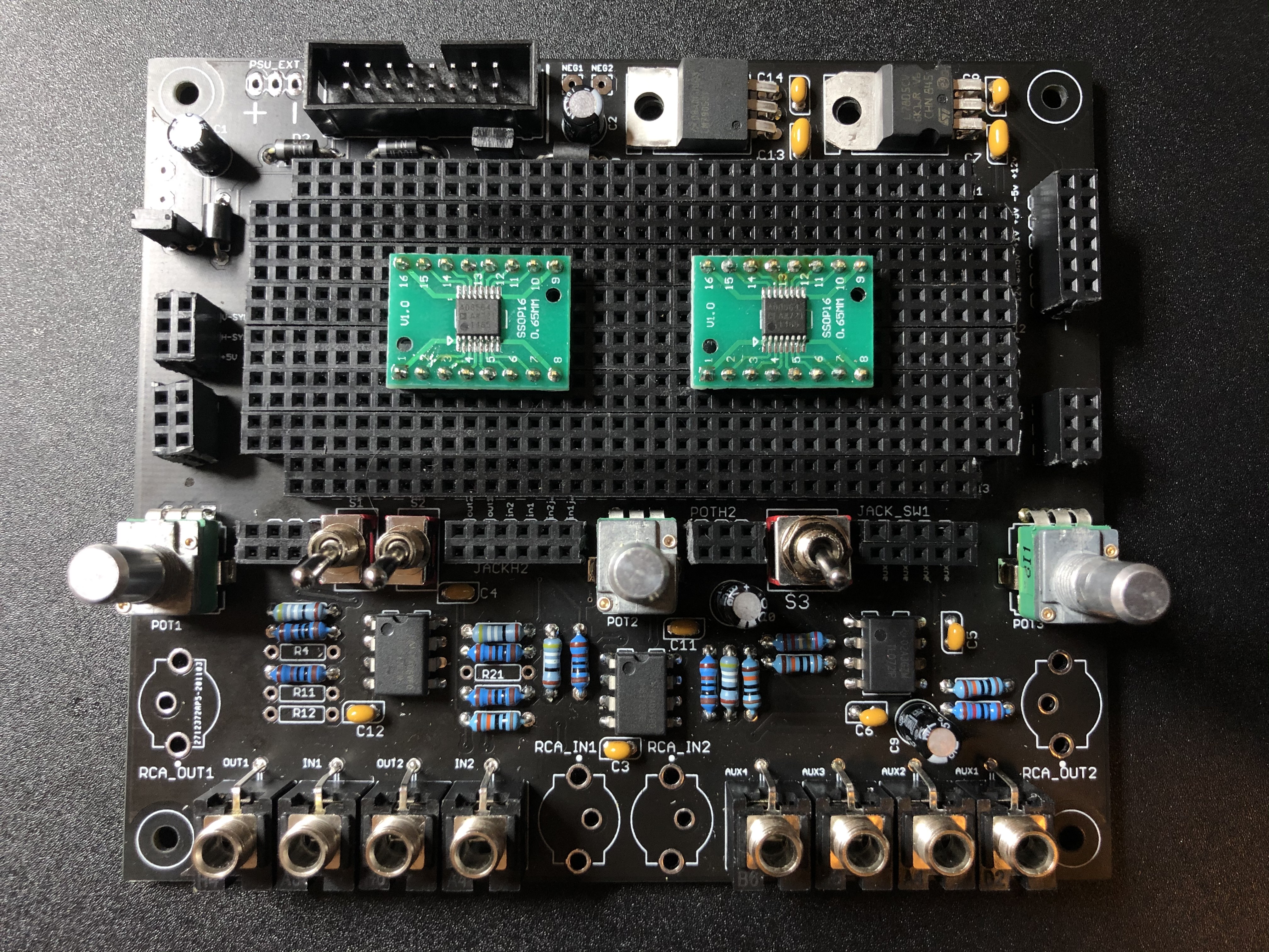
#81 — joem · 2020-12-19
Ha! I’m working on making one of my V1’s into a breadboard too! Great minds think alike.
I’ll have to place a V2 order with the Snow module when both are available…
#82 — VisibleSignals · 2020-12-19
That’s an excellent idea! You guys are clever.
#83 — Robbertunist · 2020-12-19
That’s awesome @rempesm
Are most or all of the passives the same as in the BOM? Now that I ask, I don’t remember seeing one but surely there is.
Did you have to do any major customising to make this work? @joem, have you or are you planing any useful mods to create your version of this fixed breadboard setup? Just curious but I’m really tempted to try this too.@reverselandfill, is it possible to power the experimental board from an external PSU? Like a standard 15V AC from Doepfer for example.
#84 — reverselandfill · 2020-12-19
the build files are here:

https://www.reverselandfill.org/diy/video-experiment-board-veb-v1/Link: Video Experiment Board (VEB) v1 – Reverselandfill
The BOM is included in the buildguide, because you can build it in several ways.
you can power the VEB with a dual (eurorack or bench supply) PSU. -12 and +12
I added an external power input (left next to the 16pin header)
You cannot power it with an AC brick. This board needs DC.
If you don’t have such a powersupply, you can also use 2x 9v batteries.
(PM me if you need assistance)
#85 — Robbertunist · 2020-12-19
Cheers @reverselandfill for the link & info
DC PSUs are definitely easier to source so I’m glad to see that. Is the power socket footprint on the PCB a particular standard? Ah, I’ll have a look in the build instructions & update this if the answer is there.Update: there’s a nice closeup of the power input feet in the build guide but I’m not familiar with this type of power connector

#86 — Robbertunist · 2020-12-19
A small suggestion would be to turn the 3x2 footprint of POTH1 90 degrees to match the layout of the pot. POTH2 is perfect although to the side of course.
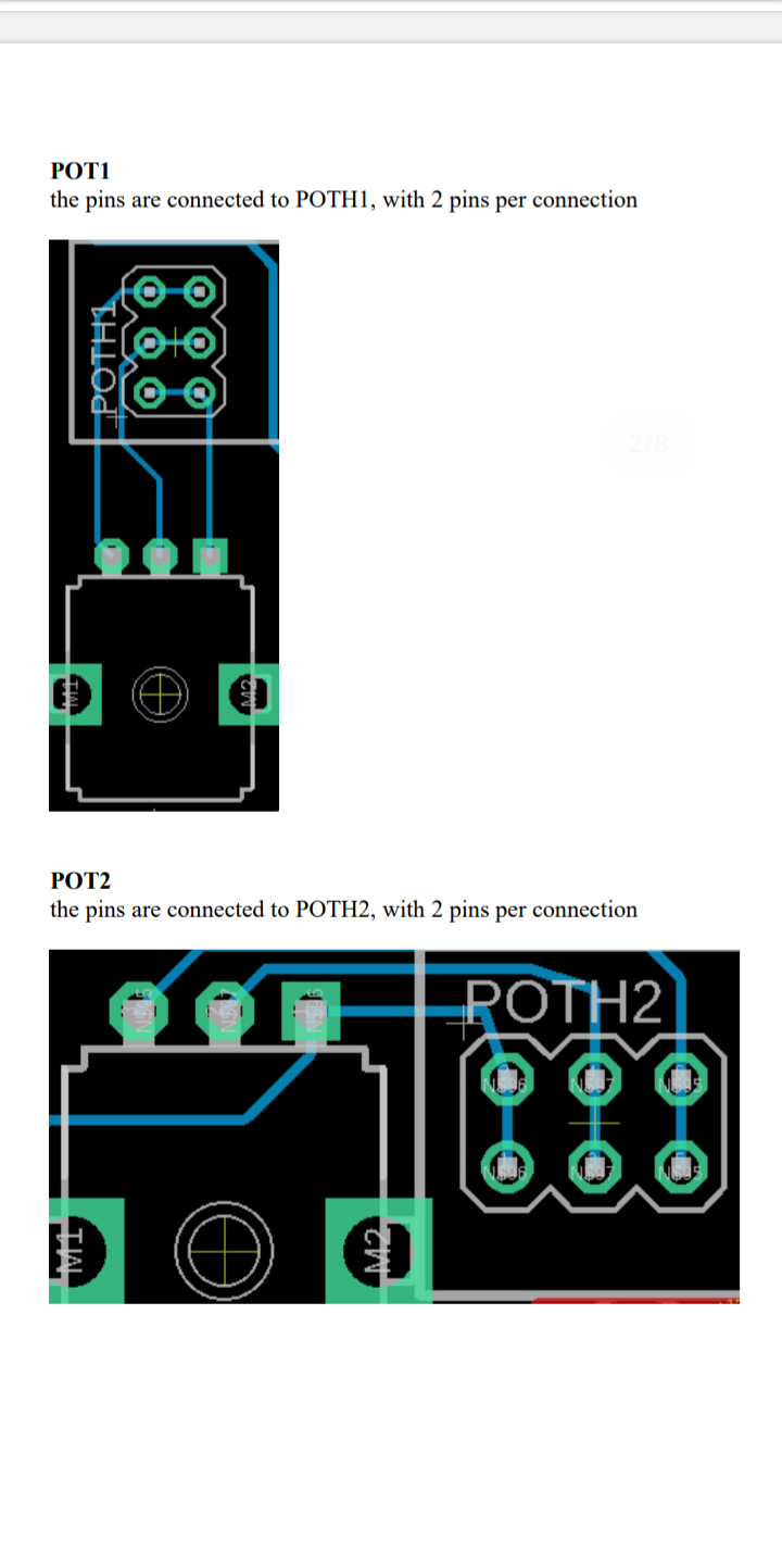
#87 — Robbertunist · 2020-12-19
What are the values of the 3x pots? Surely B10K.
#88 — joem · 2020-12-20
No, I’m planning on doing pretty much the same thing as @rempesm – I’m just waiting for my female headers to arrive. Didn’t have enough for this kind of thing already on hand when I started.
#89 — joem · 2020-12-20
The pots can be whatever value you need for your circuit. Chances are if you’re building some Cadet/Castle circuits that you’ll want B10K since that’s what most (all?) of those use, but it’s entirely up to you.
#90 — reverselandfill · 2020-12-20
in v2 of the VEB the pot & switch headers are better aligned. (and better labeled)
I mainly use 10k pots.
#91 — rempesm · 2021-01-02
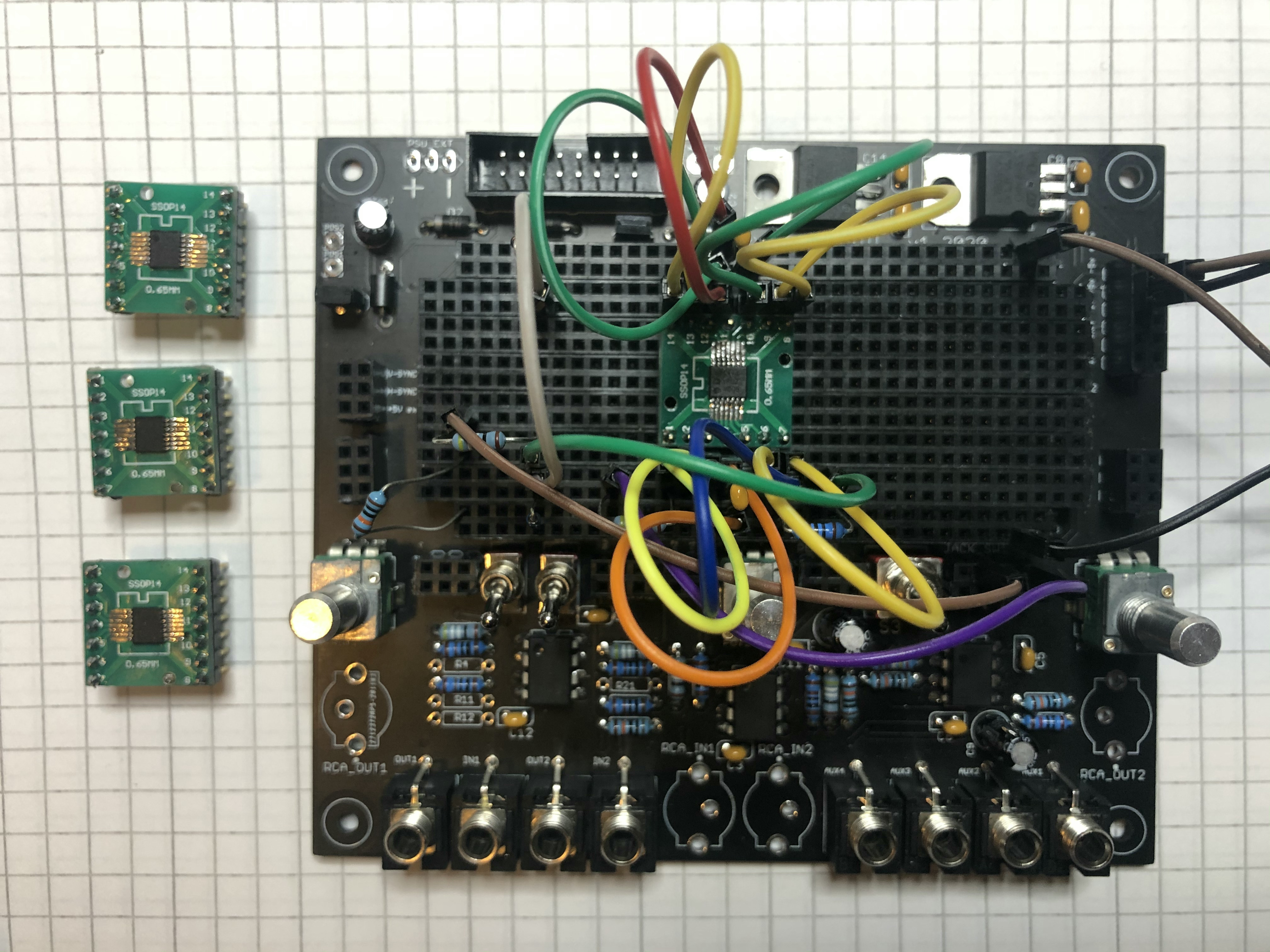
Just double checking my work on these DIP adaptor boards for ADA4851-4s with the buffer circuit on LZX’s Github. The VEB makes tasks like this feel less annoying to start. Thanks again @reverselandfill
#92 — VanTa · 2021-07-04
I see this Polarised cap between opamps non inverting input and gnd in the unity gain amplifiers for +1v and 0.5v.
What are they there for? Is it extra noise protection? Or do they stabilize the opamp in some way…?
#93 — Fox · 2021-07-04
VanTa wrote:
I see this Polarised cap between opamps non inverting input and gnd in the unity gain amplifiers for +1v and 0.5v.>>>> What are they there for? Is it extra noise protection? Or do they stabilize the opamp in some way…?
It acts as a First-Order low pass filter.
#94 — cata · 2022-07-14
Are these boards still being made?
#95 — reverselandfill · 2022-07-14
yes, I have them in stock (v2 with better graphic overlay)
Thonk also has them
#96 — cata · 2022-07-14
Nice! Yea I checked with Thonk and it looked like they were sold out which is why I was askin. Will definitely have to snag one!
#97 — reverselandfill · 2022-07-14
you can buy one (or a pack) directly from me (with some forum discount)