[WIP] 2-to-1 RGB Luma Switcher, now known as Shutter
Category: Unknown · Tags: diy, fox, shutter · Posts: 79
#1 — Fox · 2020-10-20
Hi everyone,
I have a project in the works that I hope to finish soon and start a group order once it’s tested and finalized. @rempesm and I have been working very hard on many ideas that focus on RGB and component video processing as companions to existing systems.
The first project I hope to bring all of you is a video-rate luma switcher which will switch between two sets of RGB signals.
Users may:
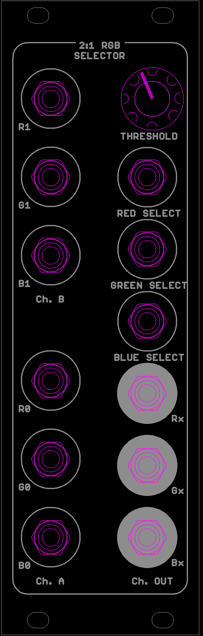
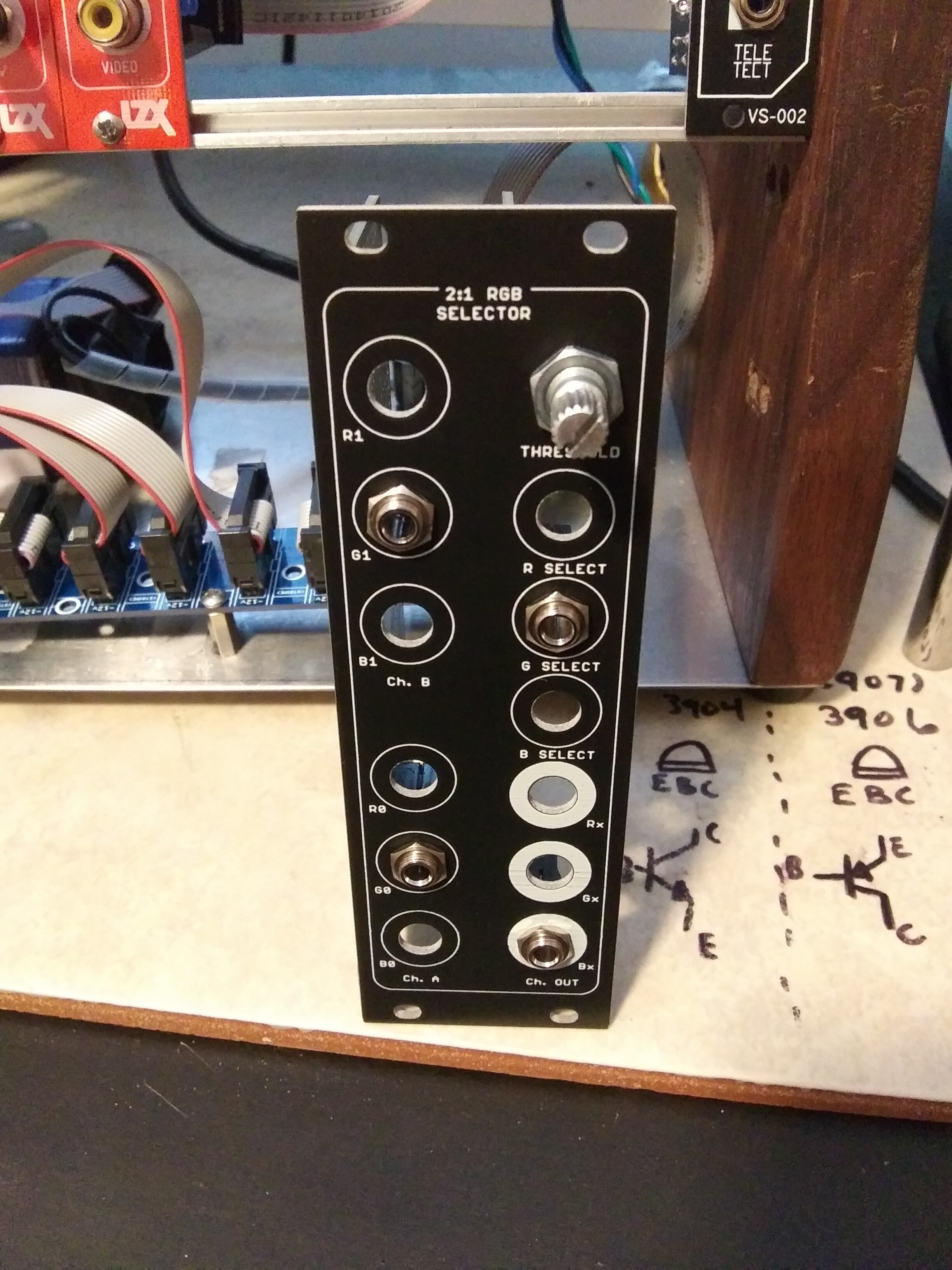
(1) Choose to switch each of the 6 luma inputs independently or all three as an RGB-set utilizing just the Red-Selector input and the “normalled” inputs of the G- and B-Selector inputs.
(2) With the use of the threshold knob, users may set the voltage at which the inputs will be switched from 0 to 1v.
(3) Lastly, without using any of the selector inputs; the threshold knob may be used to switch manually between inputs.
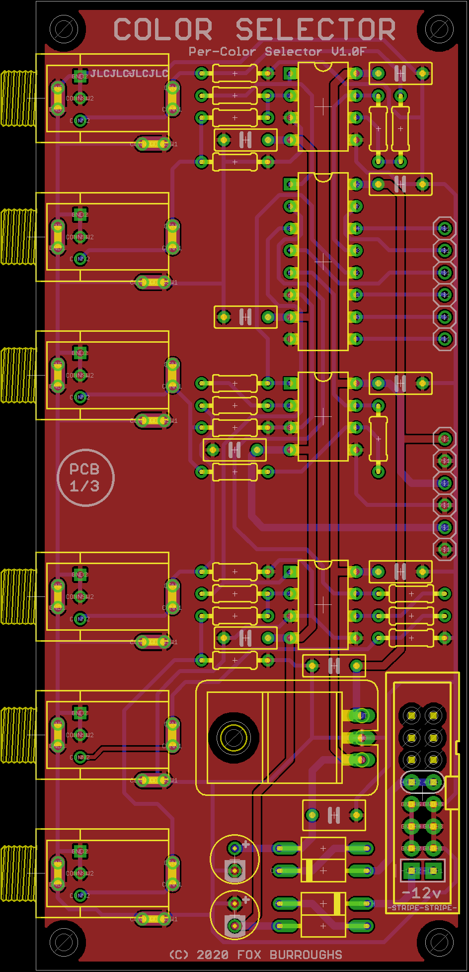
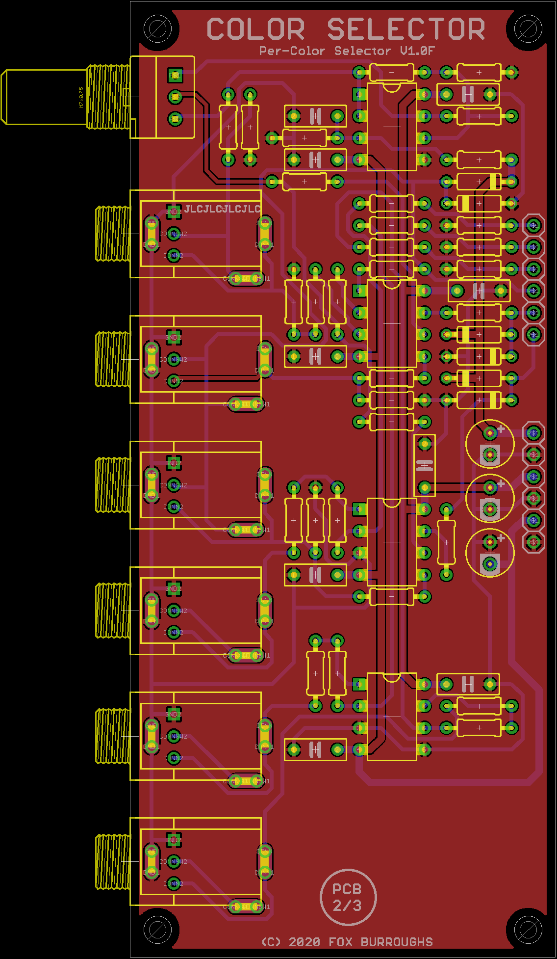
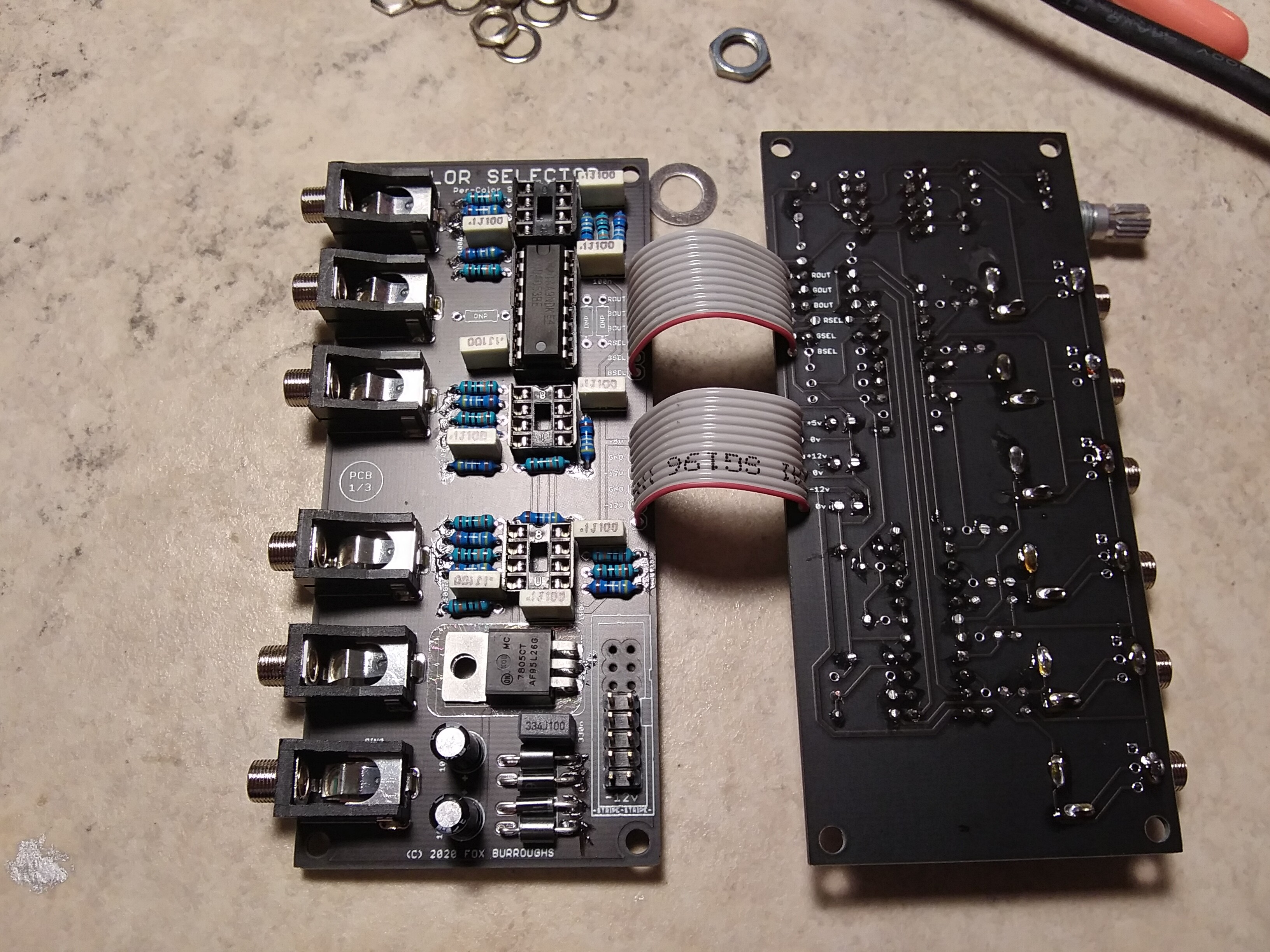
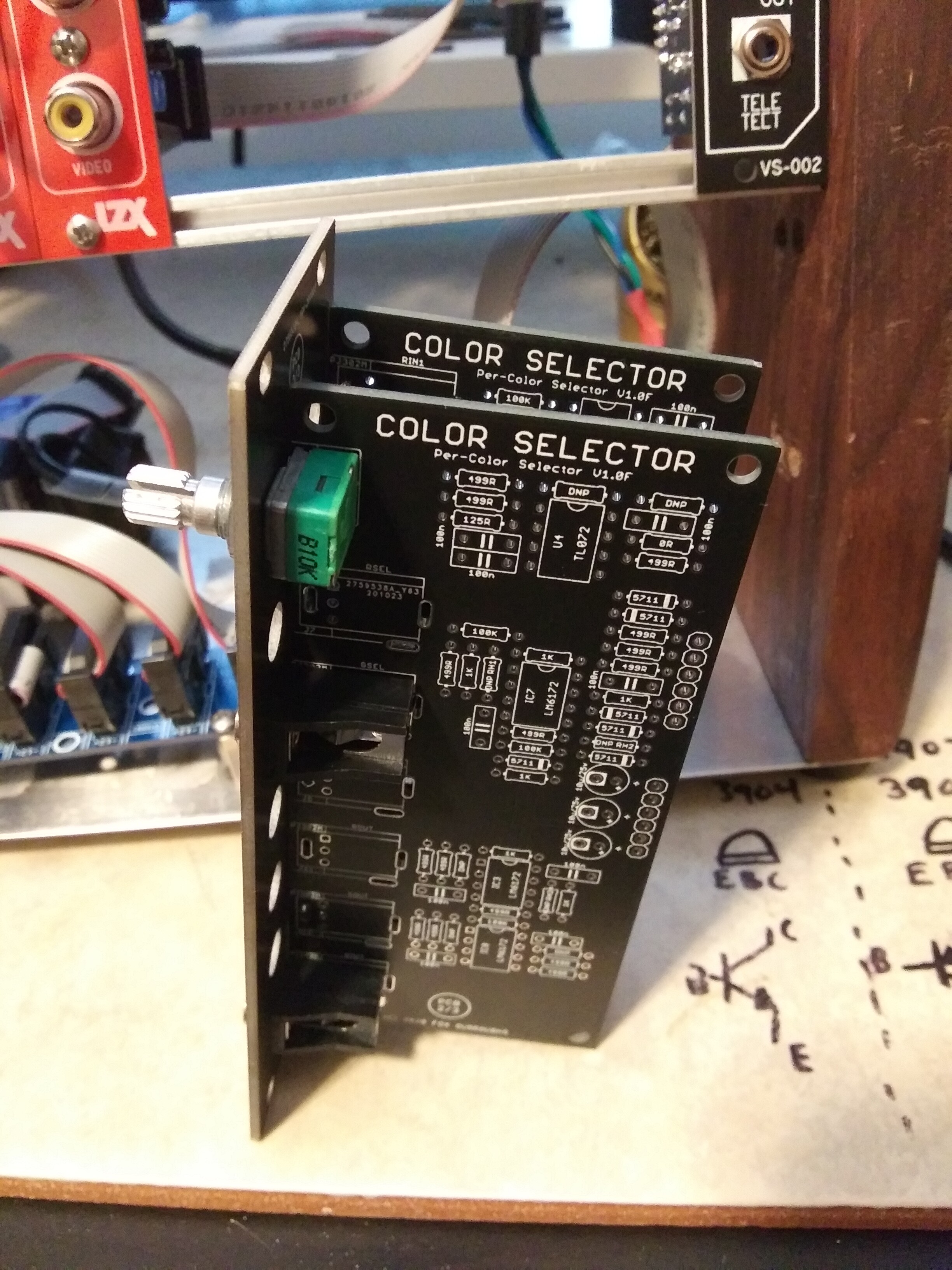
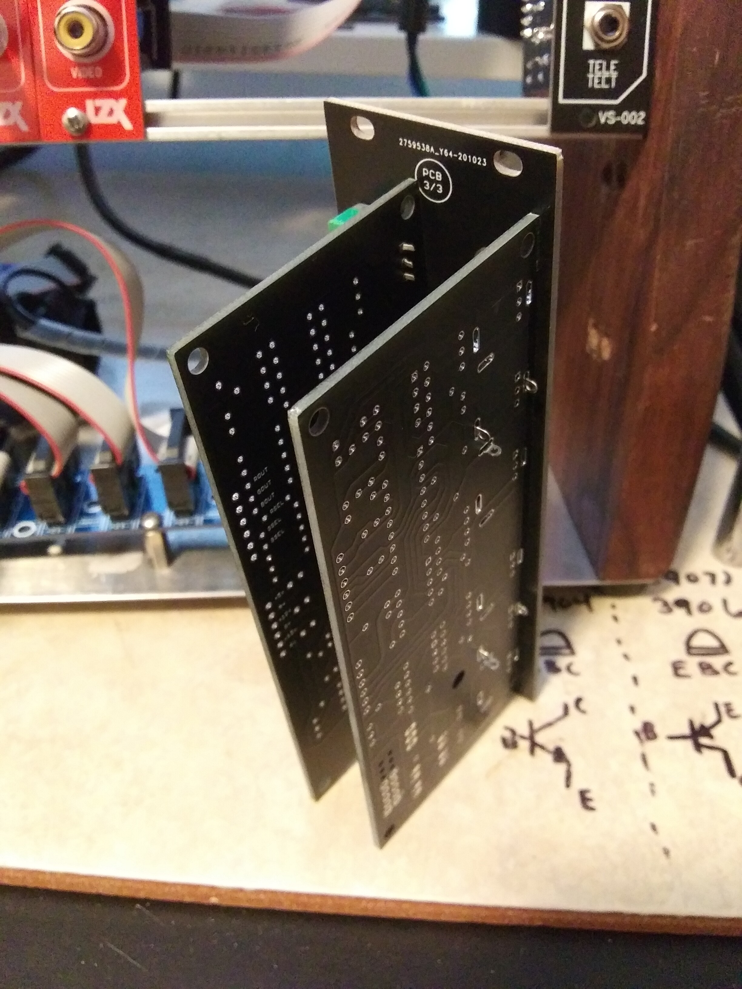
This will be an 8HP module including one faceplate and two circuit boards in a DIY format.
I have been granted permission by @Z0NK0UT to advertise this project on the forums, so please join me in the development process.
I will be sending away for this version along with several other future prototypes within a day or two. Feel free to offer any suggestions, corrections or kind words of encouragement.

-Fox
UPDATE:
Still waiting on a few more parts. Can’t wait till I can actually test them.

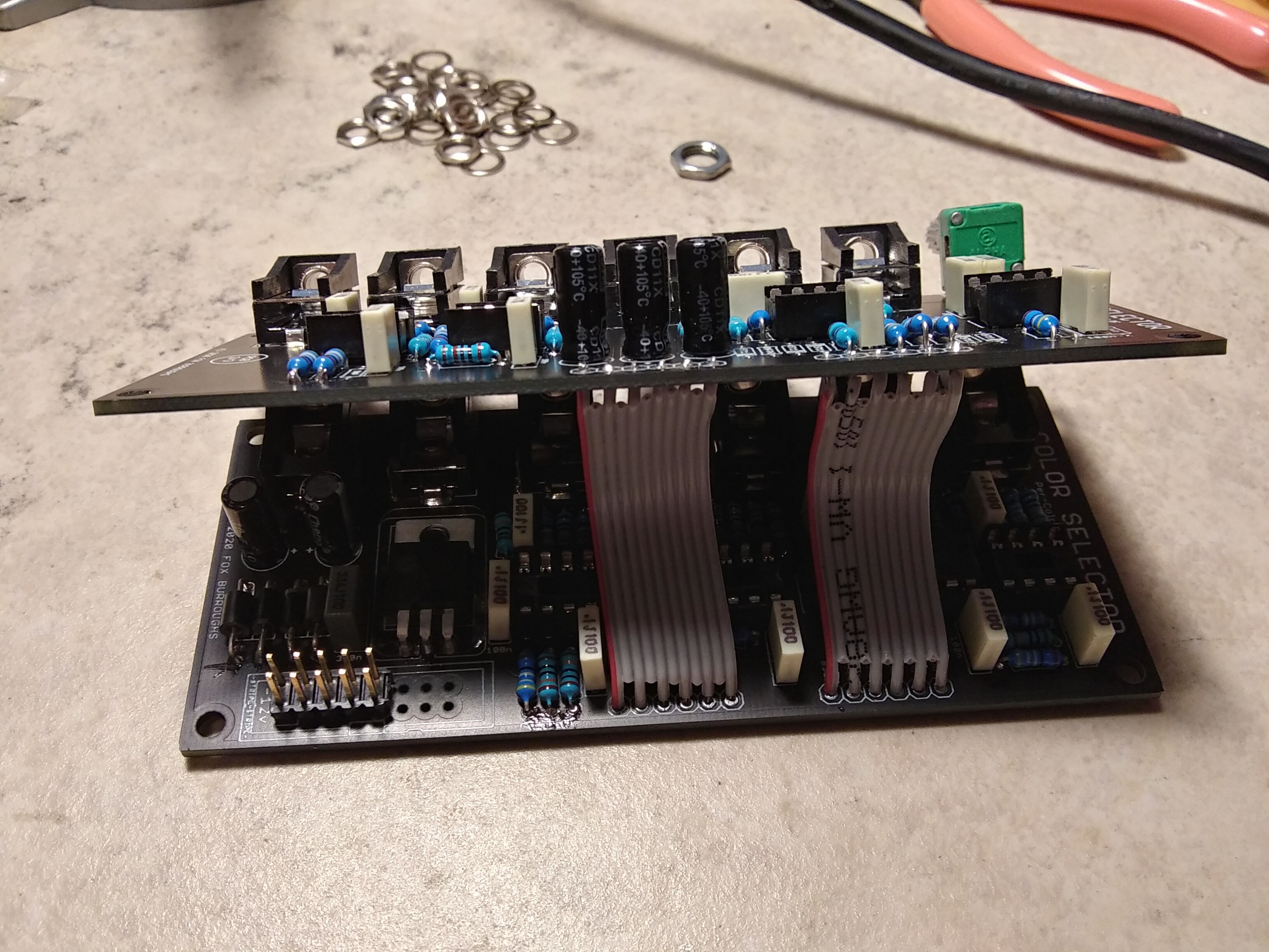
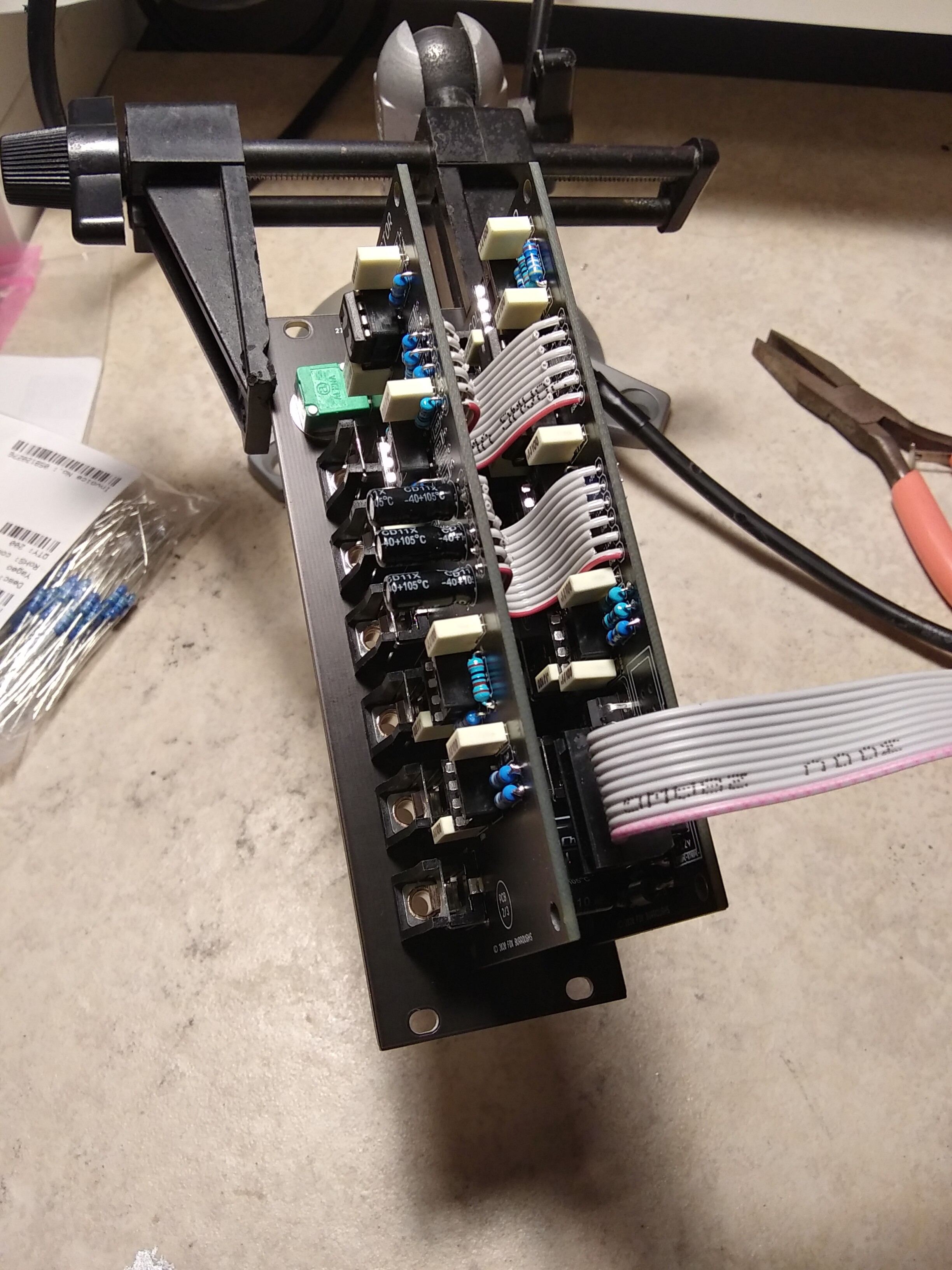
I am also still open to any and all suggestions. I don’t see much needing to change atm, but I would like to add a cutout to the top board so the power ribbon is easier to access. There’s plenty of clearance, but it is a tad inconvenient like this.
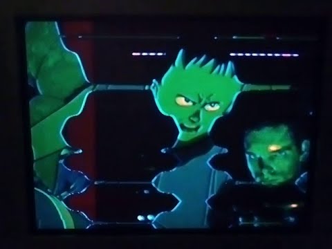
11-15-20 update - Here are some sick demonstrations from rempesm:
Corrections and modifications being made soon.
rempesm wrote:
>>>> 111520
rempesm wrote:
>>>> 111520-2
#2 — Robbertunist · 2020-10-21
Well done on a cool looking addition to a video synth setup @Fox & @rempesm & for collaborating together

Count me in on a group order and for distributing a few around Germany or Europe if neither of you are located here & it helps everyone out.My only recommendation is to make sure the silkscreen “+” sign for the 5 electrolytic capacitors is placed to the side of the caps’ footprint so it’s still visible after they’re soldered in, just in case some troubleshooting is required.
Ok, I’ll be hated for this

but a version with the smt Analog Devices quad IC presoldered at the JLC factory and the rest of the components left as is, through-hole.PS. I love the headers to link the two PCBs. Why didn’t I think of that or see it elsewhere

#3 — Robbertunist · 2020-10-21
Does this module design sound interesting to ye guys? If so, we could do a small 1 day workshop at the Pedal Store in Neukölln once it’s finalised and ready to ship.
#4 — destroythings · 2020-10-21
Id be down for in Berlin workshop. Count me in.
#5 — rempesm · 2020-10-21
Two quick notes:
I mentioned this idea as a passing thought to Fox like a week ago so all credit to him for just running with it and getting the design finished this quickly! There aren’t very many switching modules that can handle wide bandwidth signals (SSSRLabs Matrixarchate comes to mind) let alone are optimized for LZX format and feeding 3 Faders with a square wave into the CV input feels a little like overkill.
Fox’s description is great but I want to emphasize you can plug any signal into the Select jacks, from DC offsets to ramps to oscillators to external Luma video and define what voltage level causes the switch with the Threshold pot.
Generate a diamond gradient and you can choose where along that diamond shape Channel B punches through Channel A. In the external Luma video case, this means you could choose whether the darkest or lightest parts of the image or anything in between triggers the switch from A to B.
All sorts of interesting compositing possibilities come up so I’m really excited to see this released!
#6 — Robbertunist · 2020-10-21
@transistorcat, @syntonie, @reverselandfill
What do ye think of the idea & any thoughts regarding the PCB layouts or circuit design?
#7 — syntonie · 2020-10-21
Really nice idea!
I was talking of a similar principle with @reverselandfill, basically a CD4053 with buffered IO and 0-1V control over the switches, as I’ve been using this configuration to switch composite signals, thought it would be interesting to have some kind of 2 channel keyer controlled with a 3rd signal.
The selection of the inputs with the threshold knob is really neat!
#8 — transistorcat · 2020-10-21
I’ve been thinking of doing something pretty much exactly like this, but with another set of outputs so you have three full cross switches.
#9 — reverselandfill · 2020-10-21
Ha, let all the different builds come to reality!
I was thinking to inject noise into our circuit, as that looked cool with the test version. (it was actually a bug with the cd4053)
As a sort of noisy keying effect when used with the video input.
#10 — Robbertunist · 2020-10-21
The lo-fi or circuit-bender Edition

#11 — wednesdayayay · 2020-10-21
love the functionality of this module!
with a tbc2 and chromagnon on the way eventually at least one of these will be super helpful in a system. If I can get someone to build it for me I’ll be set as DIY is not really my thing.
one question
is there a reason the inputs are labeled “R1” and the select section is “RED SELECT”
I guess I’d like to see it be one of the other so
R0, R1, R SELECT
or
RED0, RED1, RED SELECT
#12 — Fox · 2020-10-21
Robbertunist wrote:
Count me in on a group order and for distributing a few around Germany or Europe if neither of you are located here & it helps everyone out.
My only recommendation is to make sure the silkscreen “+” sign for the 5 electrolytic capacitors is placed to the side of the caps’ footprint so it’s still visible after they’re soldered in, just in case some troubleshooting is required.
Ok, I’ll be hated for this
>>>> but a version with the smt Analog Devices quad IC presoldered at the JLC factory and the rest of the components left as is, through-hole.> PS. I love the headers to link the two PCBs. Why didn’t I think of that or see it elsewhere
>>>
Thanks! That would be incredible of you.
Added “+” signs.
As for the first run of prototypes, I’ll just be using thru hole 6172’s but I have done a lot of auto populated boards through JLC so it is not outside of the realm of possibilities. Worth mentioning is that they also have 6172’s on hand as well as some Analog Devices parts.
rempesm wrote:
Fox’s description is great but I want to emphasize you can plug any signal into the Select jacks, from DC offsets to ramps to oscillators to external Luma video and define what voltage level causes the switch with the Threshold pot.
Generate a diamond gradient and you can choose where along that diamond shape Channel B punches through Channel A. In the external Luma video case, this means you could choose whether the darkest or lightest parts of the image or anything in between triggers the switch from A to B.
Thanks for the additional info, Rempesm. Switching can be done via whatever signal users have on hand, including mult’ed video. I can even see the possibility of manual transition sweeps using a ramp input and the threshold knob.
syntonie wrote:
I was talking of a similar principle with > @reverselandfill> , basically a CD4053 with buffered IO and 0-1V control over the switches, as I’ve been using this configuration to switch composite signals, thought it would be interesting to have some kind of 2 channel keyer controlled with a 3rd signal.
That is precisely what we have here. Inputs are buffered, with a few 2x gain 6172’s, wired through the CD4053 and buffered again at the output. My threshold voltage by default is 0-1v, but with the swap of a few resistors , users can configure it to be anything from -5v to +5v, -0.5v to +0.5v or whatever. 0-1v is easily the most useful. I added a couple of DNP resistor footprints like the scaler has for this purpose.
We are also looking at an alternative to the CD4053 which I am going to mention to reverselandfill below.
transistorcat wrote:
I’ve been thinking of doing something pretty much exactly like this, but with another set of outputs so you have three full cross switches.
Another set of outputs? Do you mean three sets of inputs or am I misunderstanding?
reverselandfill wrote:
Ha, let all the different builds come to reality!>>>> I was thinking to inject noise into our circuit, as that looked cool with the test version. (it was actually a bug with the cd4053)
When a complete prototype is in hand, we’ll see what noise looks like and what we can do about it. I think that the addition of hysteresis to each comparator should probably get rid of any glitches. rempesm breadboarded a similar circuit with a different analog mux that introduced glitches around some transition edges. The glitches were only present near certain thresholds from what I understand and in all honesty, the effect was not a bad thing at all! Actually something I can imagine wanting to employ in certain patches.
We were looking at another IC found in the Linear Tech application notes that was made specifically for this purpose. The reason this version uses a CD4053 is because it came to mind first and because the other chip is limited to a +/-5v supply. By the time I even looked at the alternative, I already had this drawn out.

Anyhow, that other chip is probably the very best part for this project for many reasons. First of all, it has input buffers and output gain stages internally without the need for external resistors or op amps.
#13 — Fox · 2020-10-21
wednesdayayay wrote:
love the functionality of this module!>>>> with a tbc2 and chromagnon on the way eventually at least one of these will be super helpful in a system. If I can get someone to build it for me I’ll be set as DIY is not really my thing.
one question>>>> is there a reason the inputs are labeled “R1” and the select section is “RED SELECT”
I guess I’d like to see it be one of the other so>>>> R0, R1, R SELECT>>>> or>>>> RED0, RED1, RED SELECT
Not sure if I’ll be doing any complete sales this time, but someone would probably be happy to help you there.
Thanks for the faceplate CC. I had several different ideas on how to label it and apparently they all started to bleed together. The reason I have R0 instead of RED0 is because it aligns with the other projects I have in the works.
Does fit with Ch. A, B and OUT? Ch. OUT kinda bugs me but idk what else to use.
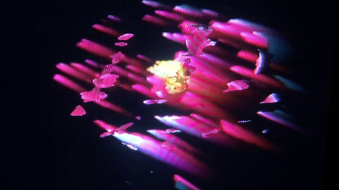
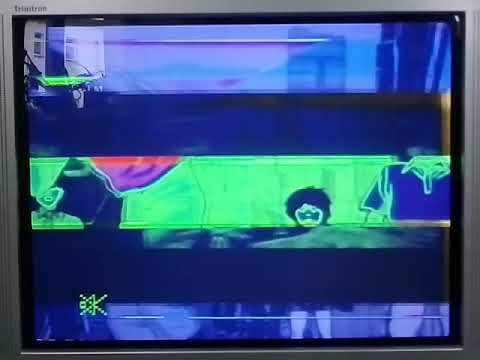
#14 — reverselandfill · 2020-10-21
We had glitches because we powered the 4053 with +12v and GND. the glitch emerged from the fact that the LOW could not get to zero. so we powered the cd4053 with +5v and -12v
Edge glitches are something I had not looked at yet. but our focus point was create dirty video glitches, so it is another approach


this is what it looked like: (patch with the freq doubler and camera feedback)
the grainy stuff come from the switcher
so that is why I rather want it back in a more controlled form.
#15 — transistorcat · 2020-10-21
Fox wrote:
Another set of outputs? Do you mean three sets of inputs or am I misunderstanding?
The idea was to have three sets of two inputs and three sets of two outputs, and three sets of key inputs (adjustable level like yours).
When the key is above the threshold, the outputs swap.
This could be patched into a full RGB switcher (like your design) but also as a panner (one input routed to either output), or a single luma four input switcher (also like yours), or a one-input four output router and some combination of weird setups
#16 — Fox · 2020-10-21
reverselandfill wrote:
@Fox>>>> We had glitches because we powered the 4053 with +12v and GND. the glitch emerged from the fact that the LOW could not get to zero. so we powered the cd4053 with +5v and -12v
Edge glitches are something I had not looked at yet. but our focus point was create dirty video glitches, so it is another approach
>>>> this is what it looked like: (patch with the freq doubler and camera feedback)>>>> the grainy stuff come from the switcher
*snip *
so that is why I rather want it back in a more controlled form.
Oh thats cool! Looks like marbling. Have you considered starving the chip using the voltage drop of series diodes? Connect +12v to the VDD pin and connect a diode’s anode to the chip’s GND and VEE pins, and the cathode to ground. Try several diodes in series. It could either be interesting or it could be way off.
transistorcat wrote:
The idea was to have three sets of two inputs and three sets of two outputs, and three sets of key inputs (adjustable level like yours).>>>> When the key is above the threshold, the outputs swap.>>>> This could be patched into a full RGB switcher (like your design) but also as a panner (one input routed to either output), or a single luma four input switcher (also like yours), or a one-input four output router and some combination of weird setups
oh cool cool. How big would that be? Whenever I design a board I am always worried about the HP, or at least worried what people would think if I “took up too much width.”
#17 — reverselandfill · 2020-10-21
Fox wrote:
Oh thats cool! Looks like marbling. Have you considered starving the chip using the voltage drop of series diodes? Connect +12v to the VDD pin and connect a diode’s anode to the chip’s GND and VEE pins, and the cathode to ground. Try several diodes in series. It could either be interesting or it could be way off
I’ll try that!
ps: I love that we are all building/designing here, open on this community forum
learning from each other, helping…
#18 — transistorcat · 2020-10-21
I was hoping to fit it into a slightly-too-dense 8hp (Which would be fine enough since there are few controls), failing that i feel like 12hp for an RGB module is not too much to ask
#19 — meudiademorte · 2020-10-21
Looks amazing. Definately in for a order!
#20 — VisibleSignals · 2020-10-21
Hello guys,
It might be worth checking out the ADG333A IC - it’s a through-hole video-rate quad SPDT switch with separate controls for each switch and it runs off +/-12V. It’s absolutely perfect for this sort of thing, and avoids the need to generate a +5V supply rail. Plus it has a higher bandwidth than the venerable 405x ICs so sharper image quality.
I used it in my Quarterizer DIY module (just announced… sorry for the gratuitious self-promotion
) which is a 8HP four-channel amplitude classifier inspired by the one from the Sandin IP. See www.visiblesignals.net for it and my other modules, including the RGB Matrix which has a dual-bus crossfader/keyer that is similar to the module you’re designing here (but it’s a fader rather than a hard switcher).
#22 — horacio2222 · 2020-10-22
i’d be down for that too!
#23 — reverselandfill · 2020-10-22
VisibleSignals wrote:
ADG333A
looked at it better: looks nice. I’ll order a few to test this!
#24 — Fox · 2020-10-22
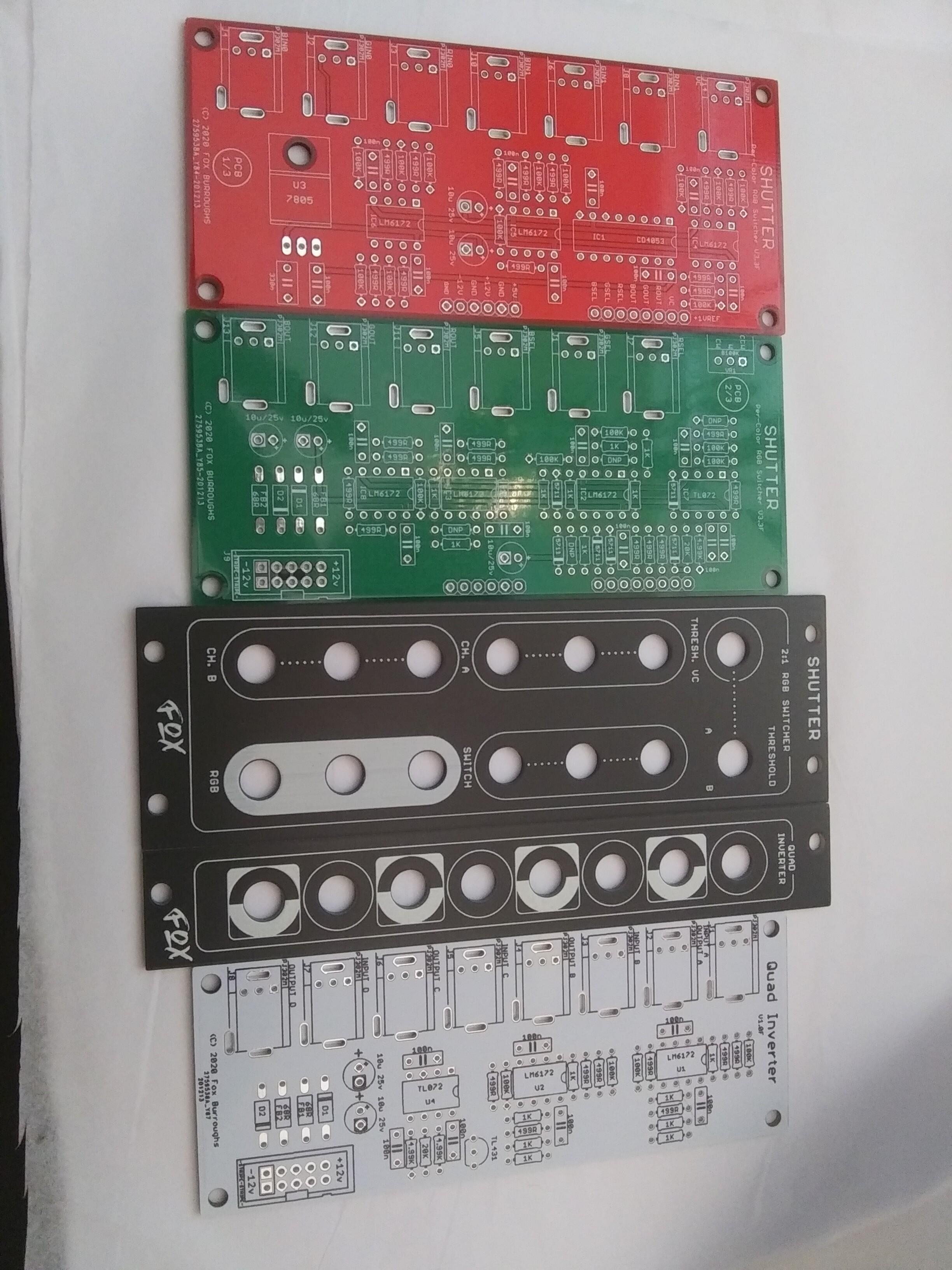
Just dropped $200 on JLC boards. This project is merely 3 out of 26 different boards in the order.
#25 — reverselandfill · 2020-10-22
ha, all video projects?

#26 — VisibleSignals · 2020-10-22
I know this feeling… when all the bundles of boards (and the ‘gift’ - different every time!) arrive in those boxes it’s so exhilarating!

#27 — rempesm · 2020-10-22
Ideally the gift is a keychain cat with bossy eyebrows which seems to happen regularly.
#28 — reverselandfill · 2020-10-22
the green roll of electrical tape is pretty cool too. . as some of you will see soon… hint
#29 — Fox · 2020-10-23
reverselandfill wrote:
ha, all video projects?
>>>
Actually, yes. Its not 26 different projects though since half of the order is faceplates.
VisibleSignals wrote:
I know this feeling… when all the bundles of boards (and the ‘gift’ - different every time!) arrive in those boxes it’s so exhilarating!
My last order that was this big came in two boxes taped together.

rempesm wrote:
Ideally the gift is a keychain cat with bossy eyebrows which seems to happen regularly.
Haven’t seen that one yet! I just hope I don’t get a t-shirt.

One of my colleagues was sent a shirt and customs held up the box for over three weeks.
#30 — VisibleSignals · 2020-10-23

#31 — VanTa · 2020-10-23
Yes! Im at least 20 characters in!
#32 — Fox · 2020-10-27
Boards are being picked up by DHL!
#33 — Fox · 2020-11-03
Everything finally showed up but my dog got skunked so I won’t be soldering today…
#34 — Robbertunist · 2020-11-03
Looks good
Regarding your dog, I hope there’s some relatively easy fix regarding them getting skunked but I can imagine it including lots of water, rinsing and slowly drying
#35 — wednesdayayay · 2020-11-03
these look great. While I do want one I think I’m still going to put together a passive 2:1 RGB switch too
#36 — Fox · 2020-11-03
Still waiting on a few more parts. Can’t wait till I can actually test them.
I am also still open to any and all suggestions. I don’t see much needing to change atm, but I would like to add a cutout to the top board so the power ribbon is easier to access. There’s plenty of clearance, but it is a tad inconvenient like this.
Robbertunist wrote:
Looks good
>>>>>>> Regarding your dog, I hope there’s some relatively easy fix regarding them getting skunked but I can imagine it including lots of water, rinsing and slowly drying >
A real pain! She thinks everything is a new friend.
We spent the whole night bathing and I can tell we’ll be doing it again very soon…

wednesdayayay wrote:
these look great. While I do want one I think I’m still going to put together a passive 2:1 RGB switch too
Do you mean with a throw switch?
#37 — rempesm · 2020-11-03
This would be good to see as well. You could just use a 3PDT switch and 9 jacks crammed behind a panel and you’re done!
#38 — Robbertunist · 2020-11-04
Fox wrote:
would like to add a cutout to the top board so the power ribbon is easier to access
Or use a right angled shrouded or unshrouded power header.
#39 — Robbertunist · 2020-11-04
Great to see the photos of your quick progress. I’d guess you’re waiting on some LM6172s, I’ve been there a long time until very recently.
I was always wondering if these type of caps (forgotten the name) would work the same as the MLCC 0.1uF Z5U caps found in the various LZX BOMs.
Interesting to see the power cable getting remodeled. I thought there was going to be really long header pins here, what’s often used on Raspberry Pi units if I’m not mistaken.
Friendly looking dog

but early November isn’t exactly ideal “dry outside in the sun” temperatures. Then again, I’m assuming you’re closer to the Canadian border rather than the Mexican border or Caribbean coast.
#40 — Fox · 2020-11-04
Robbertunist wrote:
Or use a right angled shrouded or unshrouded power header.
Always a possibility. I would hate to make them too deep, although 1.95" (49.53mm) is probably acceptable for most systems.
Robbertunist wrote:
I’d guess you’re waiting on some LM6172s
That and a few odd resistor values. The other modules I haven’t mentioned yet use some strange values, but this one uses typical 499R, 1K, 100K (and a single 125R).
Robbertunist wrote:
I was always wondering if these type of caps (forgotten the name) would work the same as the MLCC 0.1uF Z5U caps found in the various LZX BOMs.
I prefer these for several reasons. Cost is acceptable, lead spacing is consistent and convenient, plus they rest flat. I also have no qualms with routing a few traces underneath them. As far as performance, there wouldn’t be any difference as decoupling caps. I also like these if I need a cap in an audio- or cv-path. 100nF 0.1uF 100V 5% Polyester Film Box Type Capacitor
Robbertunist wrote:
Friendly looking dog
>>>> but early November isn’t exactly ideal “dry outside in the sun” temperatures. Then again, I’m assuming you’re closer to the Canadian border rather than the Mexican border or Caribbean coast.
Northern Michigan. Yesterday wasn’t bad, but each morning has been around 25*F so she stayed indoors.
#41 — Robbertunist · 2020-11-04
Fox wrote:
Always a possibility. I would hate to make them too deep, although 1.95" (49.53mm) is probably acceptable for most systems.
I wasn’t thinking out that potential issue
Fox wrote:
Cheers for the link
Film caps. Because they’re 5mm, does it make sense to put a third hole in the PCB for each of the Tapping caps that is linked/joined by the same trace? That way the footprint would be dual compatible for the smaller MLCC caps with a 2.5mm spacing & these bigger 5mm spacing film caps.We see a similar setup with the dual solder points (nonsense term surely) and traces for the switches on the cadet range, castle too I think.
Fox wrote:
Northern Michigan. Yesterday wasn’t bad, but each morning has been around 25*F
That sounds really cold! Is that cooler than average for late October & early November? Being surrounded by 2 or 3 of the Great Lakes must make for some interesting micro climatic conditions. I never thought of such an area as costal but it makes sense. Reminds me of Chicago to the west, the Windy City on one of the other lakes.
#42 — rempesm · 2020-11-16
I’ve got one of the prototypes built up from the boards @Fox kindly sent me and wanted to share two quick clips of the module in action.
First is just using two RGB stills into the Channel A & B inputs and using a Prismatic Ray into the R Select input. I go from LFO rates to vertical bars and then modulate the oscillator with Diver and other oscillators. The Threshold knob is being adjusted throughout.
https://www.youtube.com/watch?v=u2__dq3sCecThis one is a bit more complicated of a patch and features @reverselandfill’s CMix on mixer feedback duties. Basically two RGB stills are being fed in again to Channel A & B but I took the Y from both stills, mixed them in the CMix with some feedback and put that into the R Select input. So essentially both images are influencing the switching points and I’m adjusting the threshold at different points.
https://www.youtube.com/watch?v=y6JDmdBGelYThere is some delay on the Green and Blue Select inputs in these clips that we’ve since figured out but I’ll let @Fox chime in on that.
#43 — VisibleSignals · 2020-11-16
Update… stay away from the ADG333A at pixel rates, it’s break-before-make and gives horrible 0V glitches on transitions

Sigh. Sorry for the bad advice Martijn…Also, I didn’t get a roll of electrical tape in my last JLCPCB order! No gift at all
#44 — rempesm · 2020-11-16
I just got two of those as free SMT samples I was going to try out once I got some more SSOP->DIP conversion boards. What a pity they didn’t work out!
#45 — Fox · 2020-11-17
rempesm wrote:
There is some delay on the Green and Blue Select inputs in these clips that we’ve since figured out but I’ll let > @Fox> chime in on that.
Yes, thank you @rempesm.
At certain points in the video, you can see very subtle cyan lines coinciding with the transition. About one-pixel or line in width. This was due to the red input being buffered before being cascaded to the switched inputs of blue and green. Buffering twice for only blue and green and not red caused a propagation delay and has now since been modified in the schematic. The next version should alleviate this glitch.
VisibleSignals wrote:
Update… stay away from the ADG333A at pixel rates, it’s break-before-make and gives horrible 0V glitches on transitions
>>>> Sigh. Sorry for the bad advice Martijn…> Also, I didn’t get a roll of electrical tape in my last JLCPCB order! No gift at all
Is the 4053 not make-before-break? Very interesting. Thank you for the update.
I didn’t get anything either. Maybe they’re just out of pack-ins. Hard to tell what their business volume looks like right now. Due to covid, they may have had to tighten their belts like the rest of us.
#46 — Robbertunist · 2020-11-17
Nice Videos @rempesm & good work @Fox
Interesting to see the turquoise on the edges, especially towards the end of the first video. Cool that ye got it figured out & sorted already.
#47 — Fox · 2020-11-17
Thanks!
Yeah, the effect is sorted out now but I agree that it was interesting. Almost … too interesting.
Propagation delay is something they teach you about in engineering courses but one of those things you just take for granted. So many of the parts we use in everyday projects perform well beyond the required limits, but here we can virtually/visually perceive the switching limits of the LM6172.Speaking more on the delay as a positive harnessable effect, I want to experiment with it at some point. Not with 6172’s though because of the price. The idea would be to buffer an RGB set many times in series and then tap into different stages of the buffering with a 4053 or similar to access different levels of delay. Tapping into different stages per color could look pretty cool. All I need to figure out is how to animate the effect. We should save that for another thread.
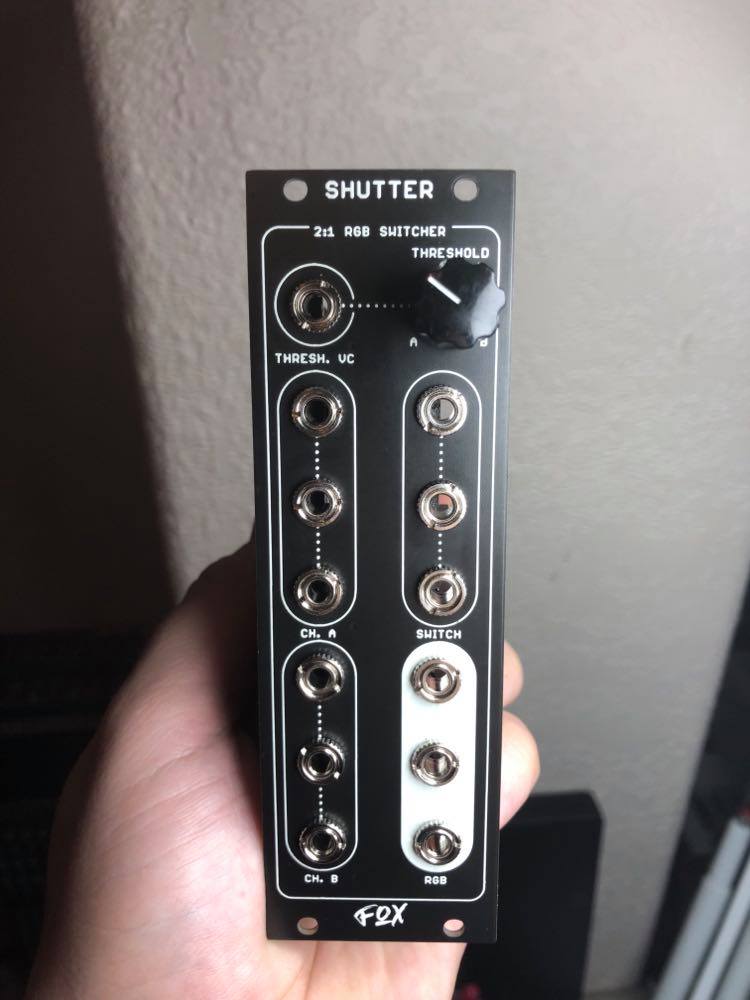
#48 — Fox · 2020-11-18
Coming up on a final version, I want more input on the faceplate. @rempesm as offered some wonderful insight but I need to hear from everyone else.
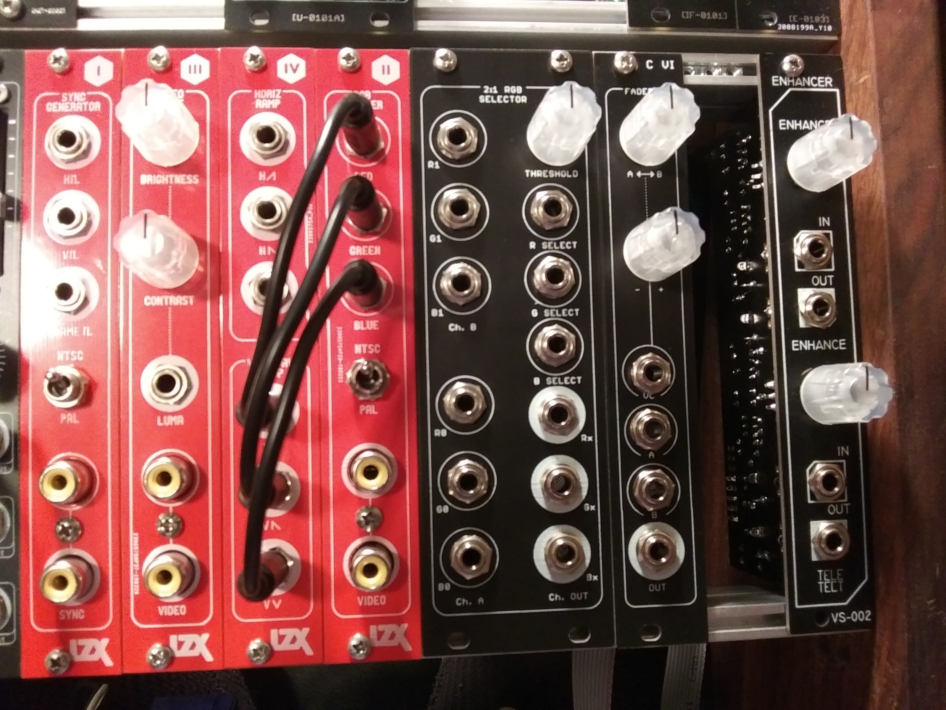
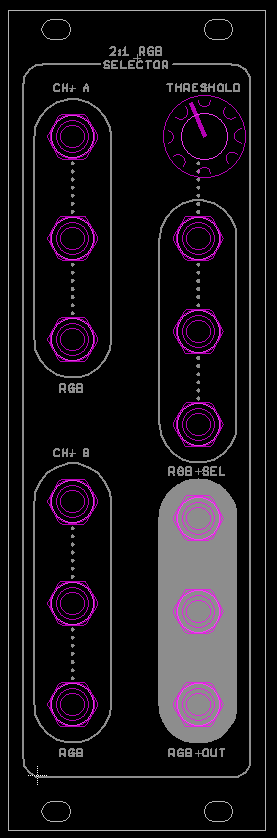
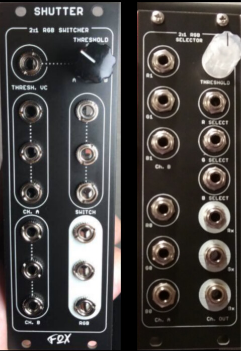
Prototype on left, finalish version on right.
—> 
I really need to make a logo for myself.

#49 — VisibleSignals · 2020-11-18
Maybe the knob in the middle (either at the top or in the centre of the panel) so the sockets line up? Or else even a wider panel and a vertical design (i.e. four rows of three sockets)? Or maybe four triangle clusters of sockets would fit into 8HP?
Working out a consistent and clear panel aesthetic sometimes isn’t easy, especially when there are board layouts to consider.
#50 — Robbertunist · 2020-11-18
Fox wrote:
finalish version on right.
The finished one looks much better because of the elongated circles around each section separating them from each other.
The RGB Select section is a Voltage Control input, why not include a VC there?
Actually they are really quite different, a 2nd or 3rd look often helps. I really like the Cadet styling of the older real one. If you could combine them, keeping the best from both, that might be cool but also cluttered. You may well of tried it already.
#51 — Fox · 2020-11-18
VisibleSignals wrote:
Maybe the knob in the middle (either at the top or in the centre of the panel) so the sockets line up? Or else even a wider panel and a vertical design (i.e. four rows of three sockets)? Or maybe four triangle clusters of sockets would fit into 8HP?
Working out a consistent and clear panel aesthetic sometimes isn’t easy, especially when there are board layouts to consider.
The layout is likely fixed at this point, for the most part at least. Both boards are finished being corrected and traced. They are basically ready to go.
I am considering another minor addition, but I want to keep these as compact as possible. I don’t think this module deserves any more than 8HP.
Robbertunist wrote:
The finished one looks much better because of the elongated circles around it section separating them from each other.>>>> The RGB Select section is a Voltage Control input, why not include a VC there?>>>> Actually they are really quite different, a 2nd or 3rd look often helps. I really like the Cadet styling of the older real one. If you could combine them, keeping the best from both, that might be cool but also cluttered. You may well of tried it.
Thanks. The elongated circles was a last minute attempt to distance myself from the Cadet Styling. I want these to look Cadet-compatible first an foremost, but also unique. LZX has been very supportive in the community so the last thing I want to do is step on any toes.
VC, yes. That is a good suggestion. I think I’ll try to fit it above the select inputs.
One more important change I made was to add dotted lines between jacks to convey the cascaded inputs. I think the clear function is important and adding the “R0, G1, etc” does indeed clutter the layout. I want to use and suggest the Befaco colored nuts, so labeling each jack would be redundant.
Oh, one more thing. I wonder if I should add “A - B” somewhere near the pot to indicate the direction that the pot activates each respective channel.
#52 — wednesdayayay · 2020-11-18
banana nuts are so nice
if the layout is set I’d say I like the elongated circles because it feels consistent without being the same
I wouldn’t mind having the A-B indication but. could live without it
#53 — Robbertunist · 2020-11-18
Fox wrote:
I wonder if I should add “A - B” somewhere near the pot to indicate the direction that the pot activates each respective channel
I guess the obvious is an A where a 0 would sometimes be found and a B where 10 is found.
Is there a typical crossfader symbol for audio or video equipment?
Just had a look & found the following:
#54 — rempesm · 2020-11-27
A few more videos. This is using 2x 2:1 switchers so three images are switched between.

https://www.youtube.com/watch?v=jvXw7fw6uQkAt higher frequencies, the window blind effect starts to look pretty neat:

https://www.youtube.com/watch?v=rVBkoDEr9X4Adding in vertex displacement from Memory Palace:

https://www.youtube.com/watch?v=iBXgWNuTpmg
https://www.youtube.com/watch?v=HRmYEEpNJTk
#55 — Fox · 2020-11-27
Thanks @rempesm! These are the best examples yet and far more impressive than I had ever imagined.
V33 (arbitrary numbers) is nearly completed and once its finalized, this is the version that will be made available. I can’t wait to see what others can do with it!
#56 — Robbertunist · 2020-11-27
The videos look awesome! The fluidity of the mixing images looks fantastic. Well done to ye on the great circuit & likewise, I’m really curious to see what people create with the module when it becomes available. @destroythings, @VanTa, @horacio2222
Any thoughts on a group buy for people in Berlin (& Germany?) when this becomes available?
#57 — Fox · 2020-12-12
Thanks to everyone who grabbed one of my Buffered Multiples, I was able to place the order for v3.3 of the RGB Switcher!
I had not said anything until now but on v3.3 I have added a Voltage Control input to switch into the threshold pot.
I also have more mults coming, but thats for another thread.
#59 — rempesm · 2020-12-23
Just stoking some flames for now.
https://www.youtube.com/watch?v=6a4wg_imjgY
#60 — Fox · 2020-12-23
Thanks for another demo, rempesm!
DesertMuseum wrote:
will you be offering any built 2:1 RGB modules? I am interested just no DIY skills. P. S. How is v3.3 coming along?
I will try to make some pre-built available. I’m having trouble finding some jacks in the US right now.
v3.3 just arrived! I am going to solder it up really soon!
#61 — sean · 2020-12-23
New panel looks great!
VC input is a great addition functionally and doesn’t hurt that it balances the left and right side of the panel.
Also cool to see that you’re building a quad inverter. Are you going to release that too? Kind of regretting that I didn’t order one of Syntonie’s when I ordered other stuff from them.
#62 — Fox · 2020-12-23
Thanks!
I’m not sure. I’ve made a lot of boards and don’t typically talk about them if someone else already offers the same function. I’m not here to step on anyone’s toes, although it would be convenient right now to have a US option.
#63 — Robbertunist · 2020-12-23
Fox wrote:
v3.3 just arrived! I am going to solder it up really soon!
Awesome! & cool to see the quad invertor in there
I seriously doubt Bastien thinks he has a patent or worldwide exclusive on such a standard synth circuit as a quad invertor. But reach out to him to get his encouragement or blessing.
#64 — brendanleespengler · 2020-12-24
I would def be interested in purchasing a pre-built!
#66 — Fox · 2020-12-26
That’s the plan! The 3 selector inputs are video rate too, but the vc input will switch to the threshold pot and connects to the other input of the comparators.
Plugging in two video signals will compare contrast of the two. In fact plugging in a different video source to all four inputs (vc and selects) could prove to be even more wild!
We’ll find out what happens soon.
#67 — syntonie · 2020-12-26
Robbertunist wrote:
I seriously doubt Bastien thinks he has a patent or worldwide exclusive on such a standard synth circuit as a quad invertor.
That’s quite similar to what I told @rempesm when we were talking about YC/YPbPr distribution amps, VU designs are really simple and it would be a bit bold of me to want to keep some weird exclusivity on it, they’re just basic electronic building blocks with the right IO impedance/bandwidth for video
#68 — wednesdayayay · 2020-12-26
love this community!
having people doing it in different parts of the world is going to be such a huge bonus
#69 — Robbertunist · 2020-12-26
syntonie wrote:
That’s quite similar to what I told > @rempesm> when we were talking about YC/YpPbPr distribution amps, VU designs are really simple and it would be a bit bold of me to want to keep some weird exclusivity on it, they’re just basic electronic building blocks with the right IO impedance/bandwidth for video
The perfect answer

#70 — rempesm · 2020-12-29
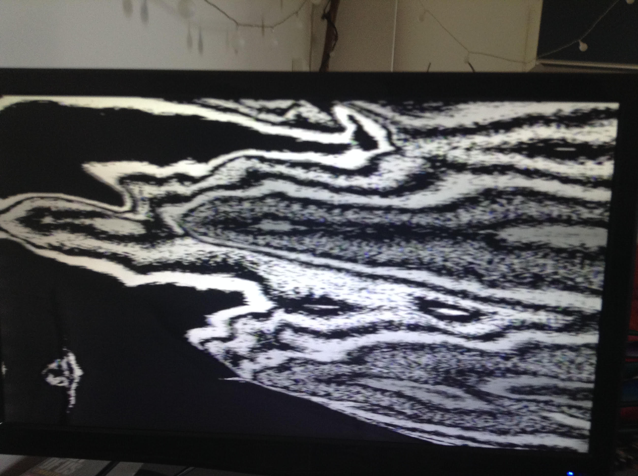
To second Fox’s response, here’s one of the first patches after I built up the latest rev:
https://www.youtube.com/watch?v=Qc4gO7M78SkThis is using the same default MemPal rose animation just processed two different ways into the RGB inputs of Ch. A & B. The Y from one still (the one making the trails) goes into the VC Threshold input. I’m using a modulated Prismatic Ray into the R Switch input (nothing plugged into G or B Switch inputs). The modulation into Prismatic Ray is a mish mash of the Y from the second still, Diver, and an LFO. Probably some other stuff I forgot but the compositing is all Shutter.
And here’s what it looks like atm:
#71 — Robbertunist · 2020-12-29
Cheers for posting the video & photo @rempesm
They both look great 
Here’s a couple of screenshot grabs mashed together. I’m 100% speculating but its nice to see see the improvement in panel layout mirrored symmetry that might of come about because of the VC input’s addition. Good work @Fox & Shutter is a cool name for it, I haven’t seen or read that until now if I’m not mistaken. It’s early here, time for coffee

#72 — visual_lies · 2020-12-29
I too would be interested in prebuilt <3
#74 — Jesse · 2020-12-30
What a perfect utility module - I’m in for 2 or 3

Great work team!
#75 — saiteron · 2020-12-30
eagerly awaiting the order thread

would love to grab a handful for sure!
#76 — jsonpayload · 2020-12-30
New panel is great, looking forward to using one of these!
#77 — Fallinggirl · 2021-02-06
Hey Fox,
I just found out about you. You’re amazing. Do you have a website or a price list for your modules? I’m dying to get Doorway, Prismatic Ray, Color Chords, Mapper and basically everything

#78 — Fox · 2021-02-06
I don’t have a site yet, but I’ll PM you with what I have available.
I don’t make any of those you listed unfortunately.
#79 — Robbertunist · 2021-04-10
Here’s a couple of links to my first use of Fox’s Shutter, it’s damn cool with video
https://www.youtube.com/watch?v=AZ4JBWsJouo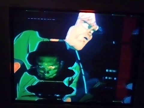
https://www.youtube.com/watch?v=A5UlVODKd-g
#80 — Robbertunist · 2021-04-10
Here’s part 3, final installment of the trilogy. It’s the shortest at 73 seconds and definitely the best imo. Hope some of ye enjoy it
https://www.youtube.com/watch?v=jY9aOt9YhEE
#81 — Robbertunist · 2021-04-10
Here’s a playlist of 4 videos using a Cadet VCO, Ramp outputs, Staircase, Doorway, VSig GainBrain & the all important Shutter & Castle 101 Quad-Gate. No DVDs, only Waveforms
Enjoy
#82 — Fox · 2021-04-10
Thanks for posting these, Robin! They all look great.
I really appreciate you explaining your patches too.
#83 — Robbertunist · 2021-04-12
Thanks for saying so Fox
I’m enjoying making this crappy looking lofi DIY videos
I’ll take it up a level soon but I’m having fun making more patches. I’ll post to Instagram where it seems more eyes find video like this much quicker than YT.