Buffered Mult, is this correct?
Category: Unknown · Tags: — · Posts: 35
#1 — jestern · 2020-11-24
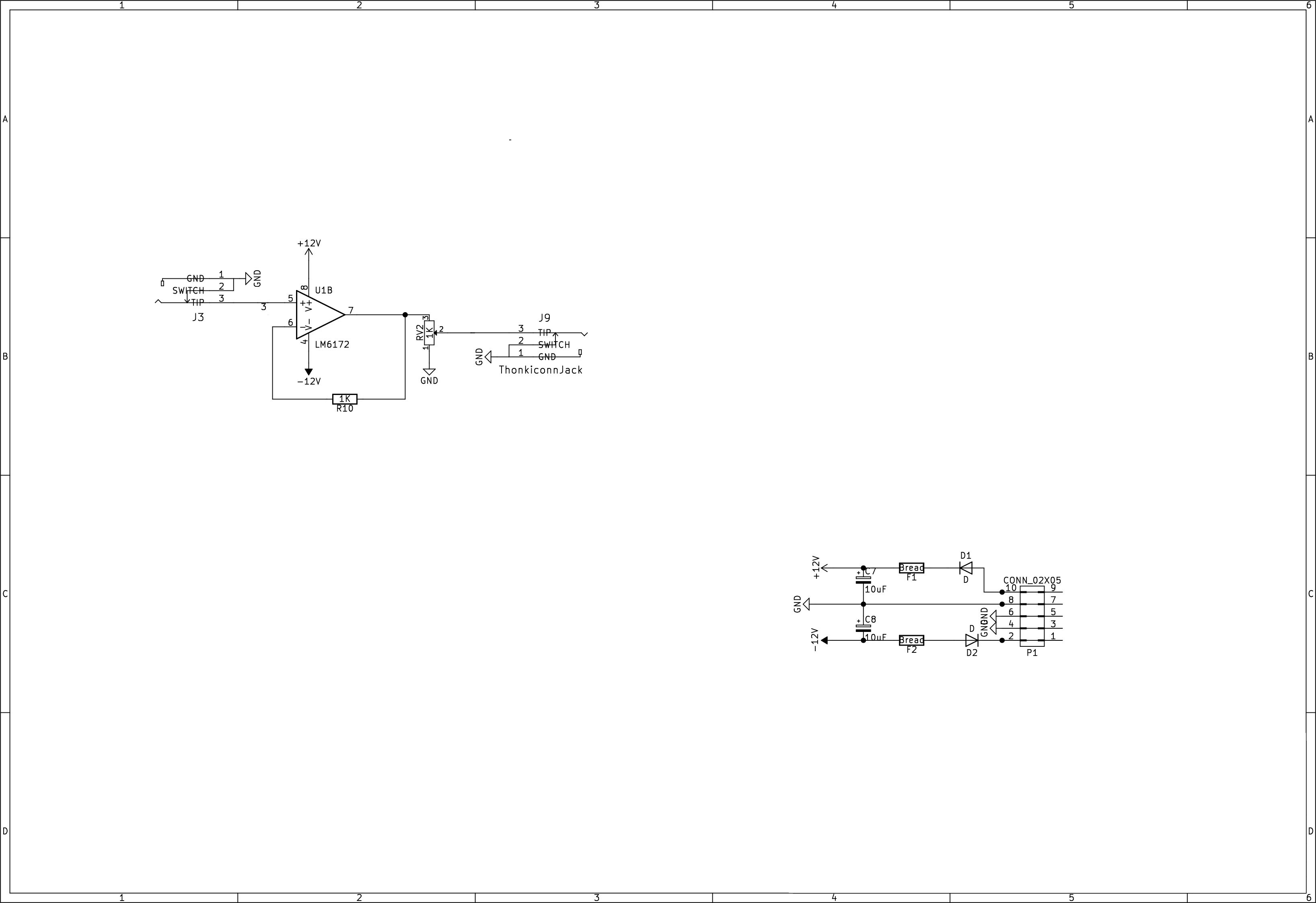
Hi there I designed a buffered mult but I don’t have a lot of experience I wanted to know if you guys think it would work and if not what are the necessary parts. I don’t mind the signal being inverted if it stays within 0 - 1V. Thanks.
AN
#2 — Robbertunist · 2020-11-24
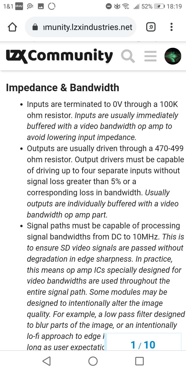
There’s generally a 499r resistor on the output & a 100K resistor to buffer the inputs of the op-amps of video synth modules.
Calling a few of the engineers around here: @VisibleSignals, @Fox, @rempesm@reverselandfill, @syntonie
Any obvious component requirements or circuit improvements to suggest to @Jestern?
#3 — Robbertunist · 2020-11-24
There’s a thread somewhere on here that covers the basics of video synth circuits.
(update: found it I think)
[WORK IN PROGRESS, FEEDBACK IN THREAD WELCOMED] > LZX Industries Patchable Video Standard V1.0> The Patchable Video Standard proposes an electrical and interface specification for wide bandwidth analog computing instruments intended for creative and expressive applications. It is optimized for, but not limited to: (1) generating and processing analog RGB video graphics in SD resolutions, (2) affordable devices which are accessible to working artists and not just big studios, and (3) maximum patcha…>
#4 — Robbertunist · 2020-11-24
Is RV2 a potentiometer that acts as a VCA?
#5 — Fox · 2020-11-24
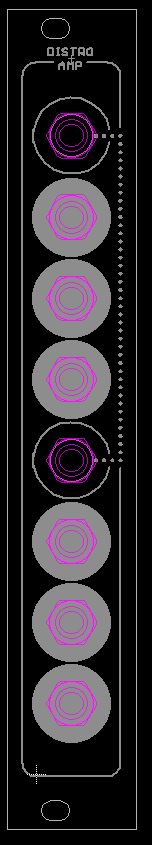
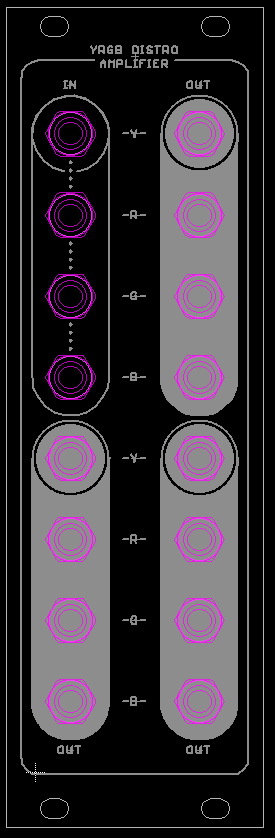
I have two coming as well. One is a 1:3 Distribution Amplifier and the other is a YRGB Distro Amp.
I’ll share the schematics via DM for now; don’t want prototype version floating around you know.
As for the schematic you drew, you should have a 100K pulldown on the TIP connector of your input and a 499R resistor at the output. The location of your pot will act as an attenuator only.
#6 — Robbertunist · 2020-11-24
At first I thought I was on the wrong thread as I incorrectly thought I had seen your RGB Crossfader panel

Cheers @Fox for confirming the resistor values. I’ve got to read and learn what “pull down resistor” means.For anyone like me who hasn’t a clue about electrical circuits.

https://en.wikipedia.org/wiki/Pull-up_resistorIn electronic logic circuits, a pull-up resistor or pull-down resistor is a resistor used to ensure a known state for a signal. It is typically used in combination with components such as switches and transistors, which physically interrupt the connection of subsequent components to ground or to VCC. When the switch is closed, it creates a direct connection to ground or VCC, but when the switch is open, the rest of the circuit would be left floating (i.e., it would have an indeterminate voltage)....
Link: Pull-up resistor
#7 — Fox · 2020-11-24
Maybe it should be called termination resistor in this case. Pull-ups and Pull-downs are terms typically used to digital electronics, but each is kind of ambiguous.
The 100k protects a disconnected input from oscillating but also creates a voltage divider with the signal’s series impedance. They also prevent a wire’s resistance from increasing t infinity, but that really isn’t relevant in this case since most user’s wires are a few feet at best.
#8 — Fox · 2020-11-24
Robbertunist wrote:
Is RV2 a potentiometer that acts as a VCA?
It will only act as an attenuator in this case. For it to create gain, it would have to be in the feedback path of the op amp.
#9 — pbalj · 2020-11-24
That pot on the output is bad news. If you turn the output all the way down, the output will be ground. If you use stacking cables for example, that would force all signals on the stack to short to ground. Put the attenuator on the input.
100k to ground on the input jack, through 499ohm to the pot. Wiper of pot to the input of opamp. 499 between output of opamp and jack.
#10 — jestern · 2020-11-25
Thanks everyone

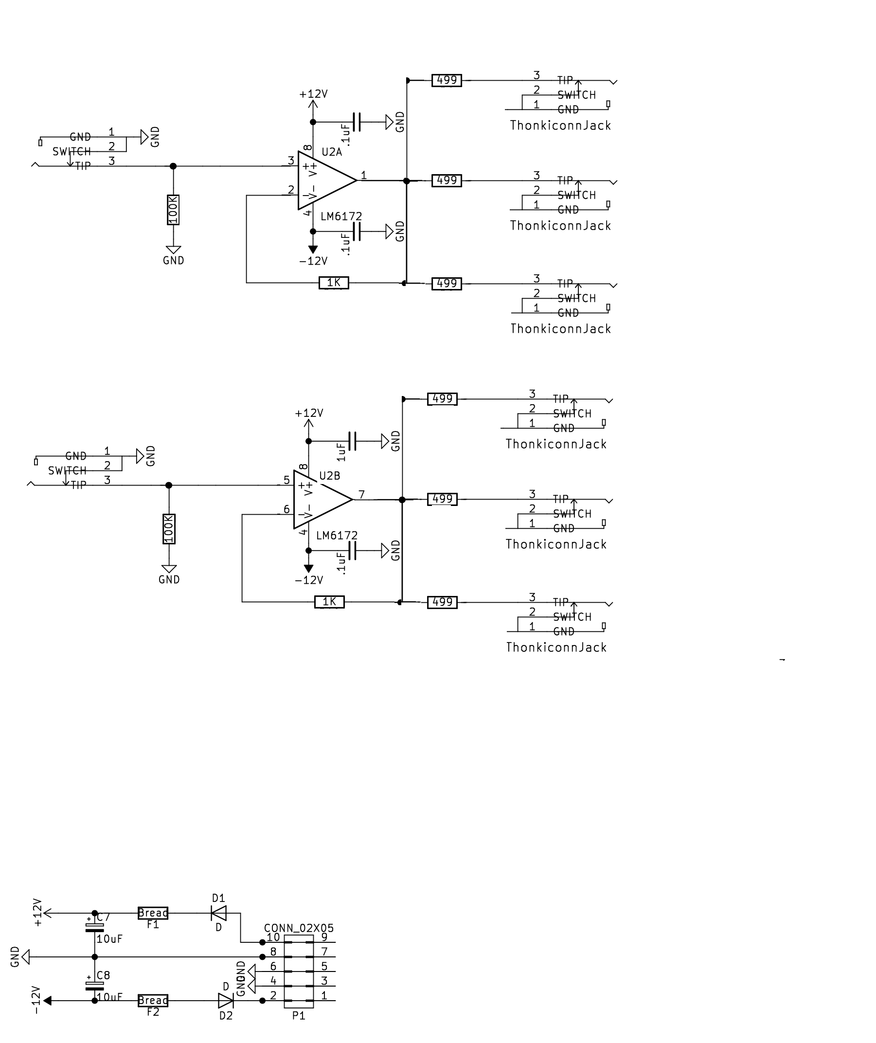
that pot was a mistake. Is it ok like this? 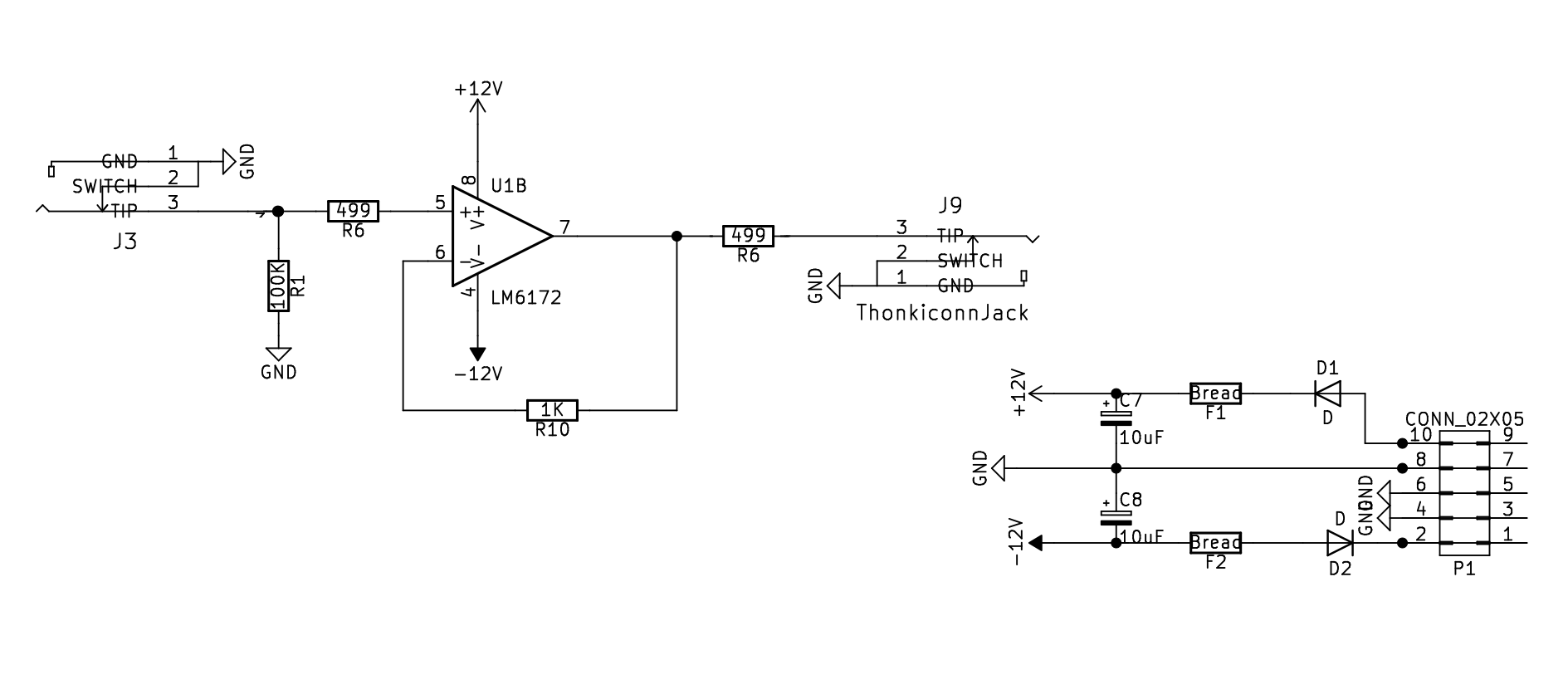
#11 — rempesm · 2020-11-25
If you add 100nF bypass caps between V+ and GND as well as V- and GND on the LM6172, that looks right to me.
Here’s one I posted in another thread:
I haven’t used that chip before but the slew rates on the datasheets for both chips look significantly different (6V/µs vs. 3000V/µs on the LM6172). > You could pretty easily compare them if you just breadboard a buffer circuit like this (remember 100nf bypass caps on V+/V-) and feed it signals with hard edges like a keyed shape or hi frequency square wave oscillators. It should be readily apparent on the output if the NJM2068D isn’t slewing quick enough. > The 1k resistors on the op amps are sug…>
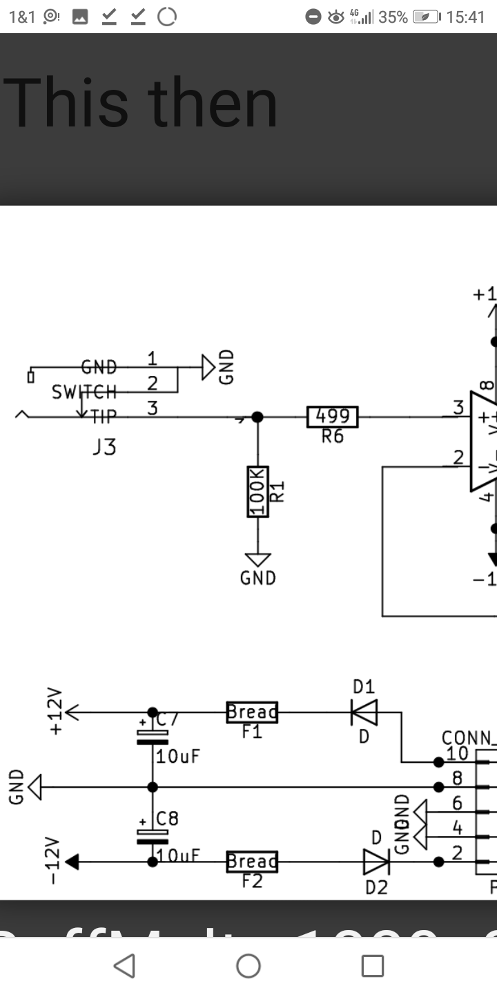
#12 — jestern · 2020-11-25
This then
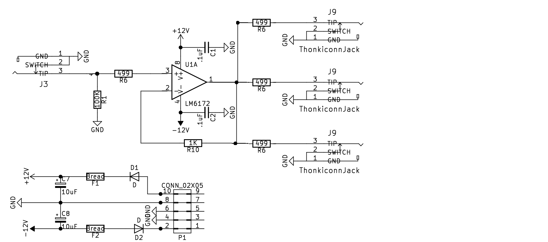
#13 — transistorcat · 2020-11-25
This is starting to look a lot like a proper buffered mult
#14 — reverselandfill · 2020-11-25
if you have an unused opamp stage (like in your schematic above), you need to do this:
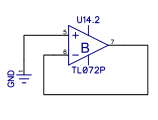
but I recommend to just add another buffer on your pcb.
in the LZX schematics the output jacks switches are not connected to GND.
#15 — Robbertunist · 2020-11-25
On the input section the 100K is there as a pull-down resistor but what is the 499r doing after? Adjusting the Voltage to a bandwidth of 1V or stopping or limiting a hot signal into the op-amp?
#16 — jestern · 2020-11-25
ok what about now?
#18 — VisibleSignals · 2020-11-25
Best not to wire the socket switch pins to ground - that will mean you short the tip of the plug to ground briefly as you insert it. On the output side shorting the op-amp to group (via 499R) when no plug is inserted loads down the op-amp unnecessarily. In general leave the switch pin unconnected on outputs and use a small series resistor on inputs.
#19 — Robbertunist · 2020-11-26
A nice trick to add to your circuit is to normalise the second input to the first input (might by incorrectly phrased), that way you’ve six cloned outputs if nothing is plugged into the second input.
I’ve seen this done on other threads by some of the various circuit designers here. A resistor was required but where exactly the first & second inputs connect, I can’t say sadly. I’ll scout for some of the threads & post a link if I get lucky.
#20 — Robbertunist · 2020-11-26
@jestern, here’s a couple of screenshots of other circuits found on here that show what Adrian was talking about.
#21 — jestern · 2020-11-26
Perfect thanks guys!!!
#22 — syntonie · 2020-11-27
It is to reduce settling time , as per LM6172 datasheet (https://www.ti.com/lit/ds/symlink/lm6172.pdf)
REDUCING SETTLING TIME The LM6172 has a very fast slew rate that causes overshoot and undershoot. To reduce settling time on LM6172, a 1kΩ resistor can be placed in series with the input signal to decrease slew rate.
#23 — VisibleSignals · 2020-11-27
^^^ Bastien’s advice is solid, definitely put those series input resistors back in…
#24 — Robbertunist · 2020-11-27
Merci Bastien

I’ve got to read the datasheet again. I’ll pick up more next time as I’ve learned alot on here since first attempting to take in all the various info there.
#25 — syntonie · 2020-11-27
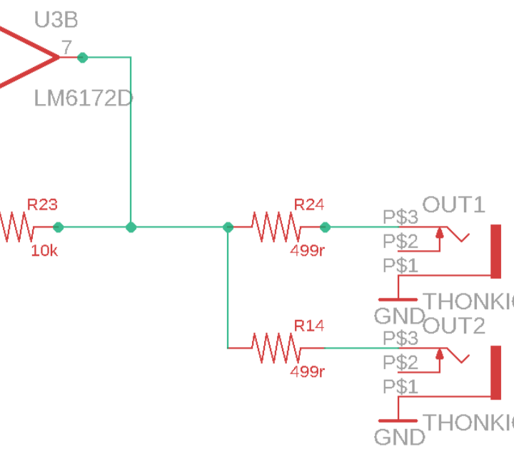
About daisy chaining using the switch from a jack, best is to take the output of the op amp (before the output resistor) and connect it to the switch pin of the jack.
Not sure if a resistor is needed in between, as it will only be connected internally. Didn’t used such resistors in VU002 (where full wave rectification stages are daisy chained).
Taking the output of the circuit (after the 499R) will work too, but will be a little bit more attenuated (as each input connected will add a 100k resistor to ground), though there is some “headroom” since 499R is quite small compared to 100k (meaning it can be connected to multiple inputs without too much attenuation).
#26 — VisibleSignals · 2020-11-28
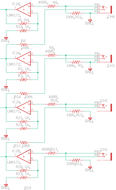
Again I agree with Bastien’s comments. But one note of warning - in my Quarterizer module I took the output from each input’s buffer op-amp directly to the switch pin of the next input socket, and it caused problems with ringing on the third and fourth inputs, even when I used a small series resistor. But, since that doesn’t happen on the VU002 it’s likely that some other aspect of my circuit was contributing to the problem. My fix (which probably isn’t appropriate for a buffered mult) was to configure the buffer op-amps for 2x gain (which the design needed anyway) and then use a 100K/100K voltage divider from the buffer/gain op-amp into the next input, like this:
Until you build your whole circuit you probably won’t know for sure what the potential problems might be. I recommend bread-boarding and prototyping all your circuits… sometimes even a simulation won’t reveal the problems you might experience.
#27 — mrfang · 2020-12-15
Regarding buffered multiples, can someone please educate me on a specific reason not to use a much less expensive TL072 instead of the LM6172? For other (non-mult) usages in video circuits the TL072 doesn’t work, but an experienced circuit designer I know says that for unity gain mult usage it’s fine, and it looks fine to me visually when running video rate signals through a buffered multiple that uses them.
#28 — joem · 2020-12-15
Using a TL072 isn’t going to break anything (just in case anyone’s worried about that), but it will make your picture less sharp if you’re using it with video with fine detail/sharp edges. If you’re not using video with fine detail/sharp edges, you may not notice it. Even with fine detail, the drop in sharpness might not bother you, and if not, then go right ahead and use the TL072.
As I understand it (not a pro, all self taught!), the reason is due to the slew rate and the bandwidth…
The slew rate is the speed at which signals can change. In the TL072, the stated slew rate is 20 V/μs, and since we’re usually dealing with voltages of just 0-1V in the LZX world, you can divide that down to find out the approximate slew rate for 1V of change, which works out to 1V per 0.05μs. While that’s pretty fast, it’s not nearly as fast as the LM6172’s slew rate of 3000V/μs, which for 1V works out to something like 1V per 0.0003 μs. Hence sharper images, if the input images have sharp changes.
I’m a bit less clear on bandwidth (I feel like it’s just another way of expressing the slew rate, like one is a function of the other?), but I think it means the higher the bandwidth the higher the frequencies it passes (without attenuating too much). The TL072’s unity gain bandwidth is 3MHz, while the LM6172’s unity gain bandwidth is 100MHZ. So with 3MHz bandwidth, the TL072 can pass some video rate signals, but higher frequencies (aka finer details) will be attenuated. If you looks at the gain vs. frequency graphs in the datasheets you can see how they compare. They might appear to have similar shapes, but if you look at the numbers you’ll see the LM6172’s range is bigger.
(Please anyone correct me if I’m wrong!)
#29 — VisibleSignals · 2020-12-15
Spot on
Post must be at least 20 characters LOL.
#30 — mrfang · 2020-12-15
That’s helpful. What test condition would illustrate the potential difference? I’ve tried oscillators in different ranges, camera inputs, and other signals, and I can’t see any difference (in sharpness or otherwise) between the input signal given to a buffered mult using TL072s and the output, even when blown up on a 40" monitor.
#31 — VisibleSignals · 2020-12-15
Test pattern generators are designed to product images to test the capabilities of equipment in scenarios like this. I would expect a high resolution vertical line generator would be a good worst-case scenario, and a pixel-width cross-hatch/inverted cross-hatch.
Also, a larger, higher resolution display would obviously make it easier to see potential degradation. And two sharp-edged signals, side-by-side, one through the op-amp and one direct.
#32 — mrfang · 2020-12-15
I saw an old Dave Jones post that said this: “analog video is considered to peak out around 6.5 to 7 Mhz for DV. And typically that’s filtered to a little over 5Mhz, like broadcast analog video was.”
So is 3-5 MHz the range where I should expect to see issues? I can also do some tests on a scope tomorrow.
#33 — VisibleSignals · 2020-12-15
Interesting. I’m from Australia so I’ll talk about PAL. Assuming you have cyclic pattern that repeats 360 times per line (such as alternating full black/full white values which most people would agree is a valid and useful example of 720 pixels per line) and given approximately 52uS of active video per line (https://en.wikipedia.org/wiki/PAL) I calculate that alternative waveform as having a frequency of around 6.9MHz, which is not that far off 5MHz. It’s worth remembering that filters have an attenutation slope, so it’s also all very analog at that point
#34 — reverselandfill · 2020-12-15
My experience with slow opamps (fake lm6172 for example) was very noticeable.
The testcase was a Triple function generator with camera input. Edges were blurry, which gave a shifted color effect when connected to RGB
as a test, look at squarewave edges (by using a hardkey or Castle module on the camera input)
compare it side by side with the ‘fast opamp module’
#36 — rempesm · 2021-06-03
Excellent, glad to see you’re diving in and making your own circuits!
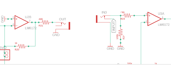
There’s a couple issues going on there but have a quick look at this single buffered mult schematic and see if the solution jumps out at you:
rempesm wrote:
>>>
One quick question–where is SW1A and R16 heading off to?
EDIT: Oh whoops looks like I got this in after your post was deleted. Hope this helps, anyway!
#37 — vhsdestroyer · 2021-06-03
A luma encoder! I had the idea after building the Telewizor and thought to myself, the circuitry to the monitor is actually extremely simple. I read through this forum thread and thought it would be nice to incorporate an encoder into the preview.
@creatorlars> , would you mind taking look at this? Before I start tracing the signal or troubleshooting my layout, I just want to verify that there aren’t any glaring errors in my circuit. I omitted the AD724 NTSC/PAL switch circuitry, and I think I have the correct circuit for NTSC? > The goal is to have a simplified, monochrome version of C2 with an attenuator and luma output. My C2 is a little deep for my travel case, I never use RGB anyway, and my wired-up banana and BNC jacks were starting t…>
Being that a lot of the heavy lifting of the design is already completed its more of an opportunity for familiarize myself with KiCad and try to understand how the encoding process works. I’m currently laying out the cadet RGB encoder and planning to normal the RGB channels into the encoder for a monochrome output to CBVS. Once that is done I will start a new thread asking for help from the community to look over the design for glaring faults.
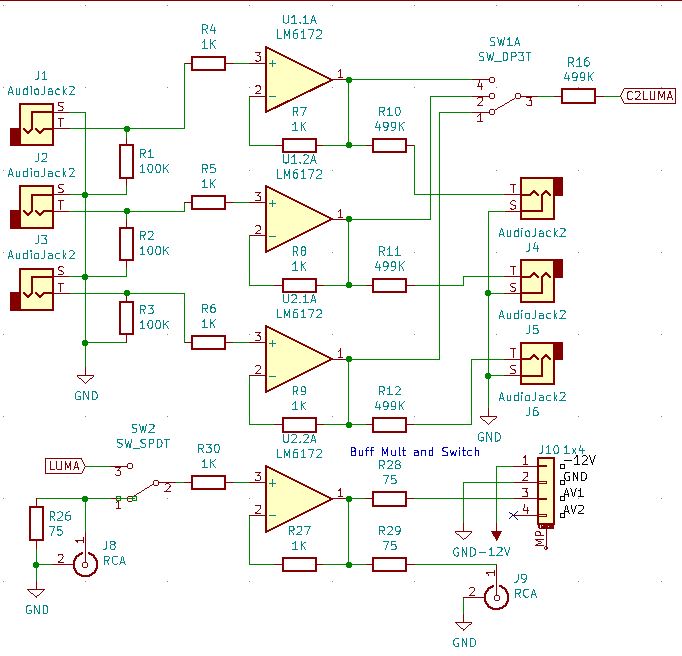
This is the portion of the circuit that will switch/mult the luma in and switch between the CVBS video streams.Also there were some mistakes here that are updated now thanks to Fox, I have a bit more figuring out to do on the rest of the schematic, mainly using RCA sync instead of 14 pin, so once its not totally messed up I will post the full schem.