[WIP] SNOW - Analog video noise
Category: Unknown · Tags: noise · Posts: 56
#1 — reverselandfill · 2020-11-29
After a successful prototyping session yesterday with the VEB,
I came up with a new project called “SNOW”.
The idea is to make a Video Noise Source module .
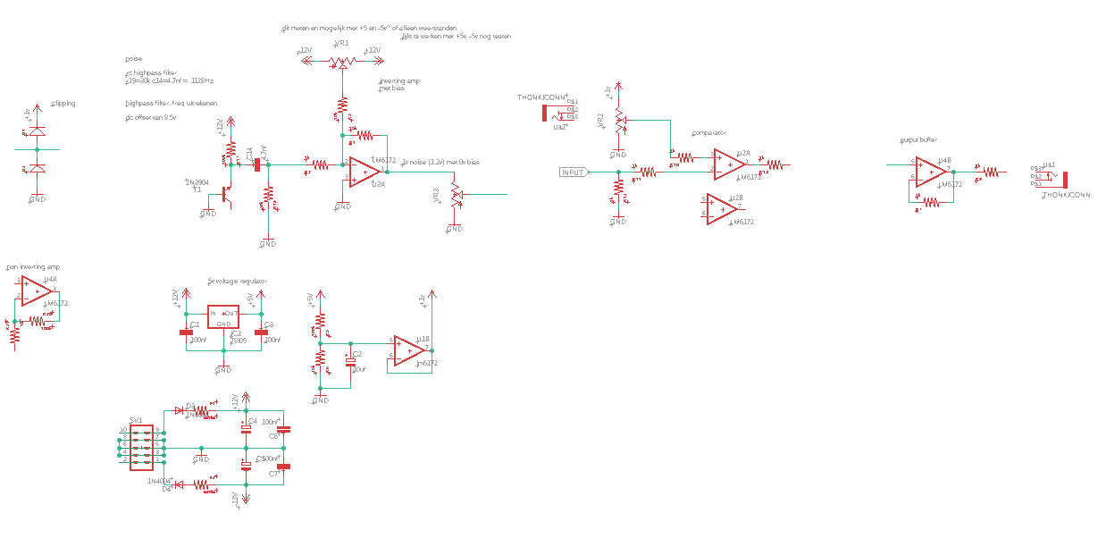
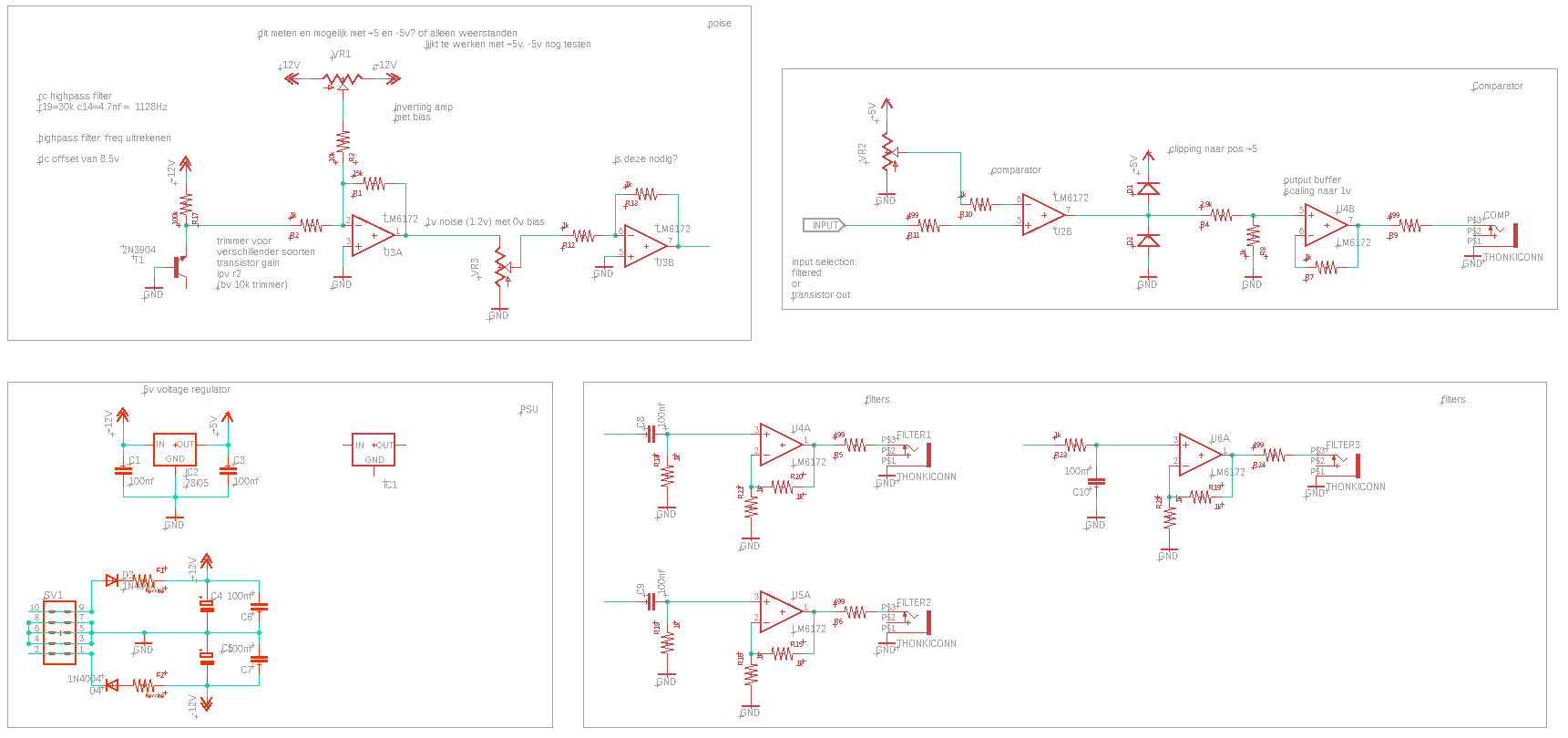
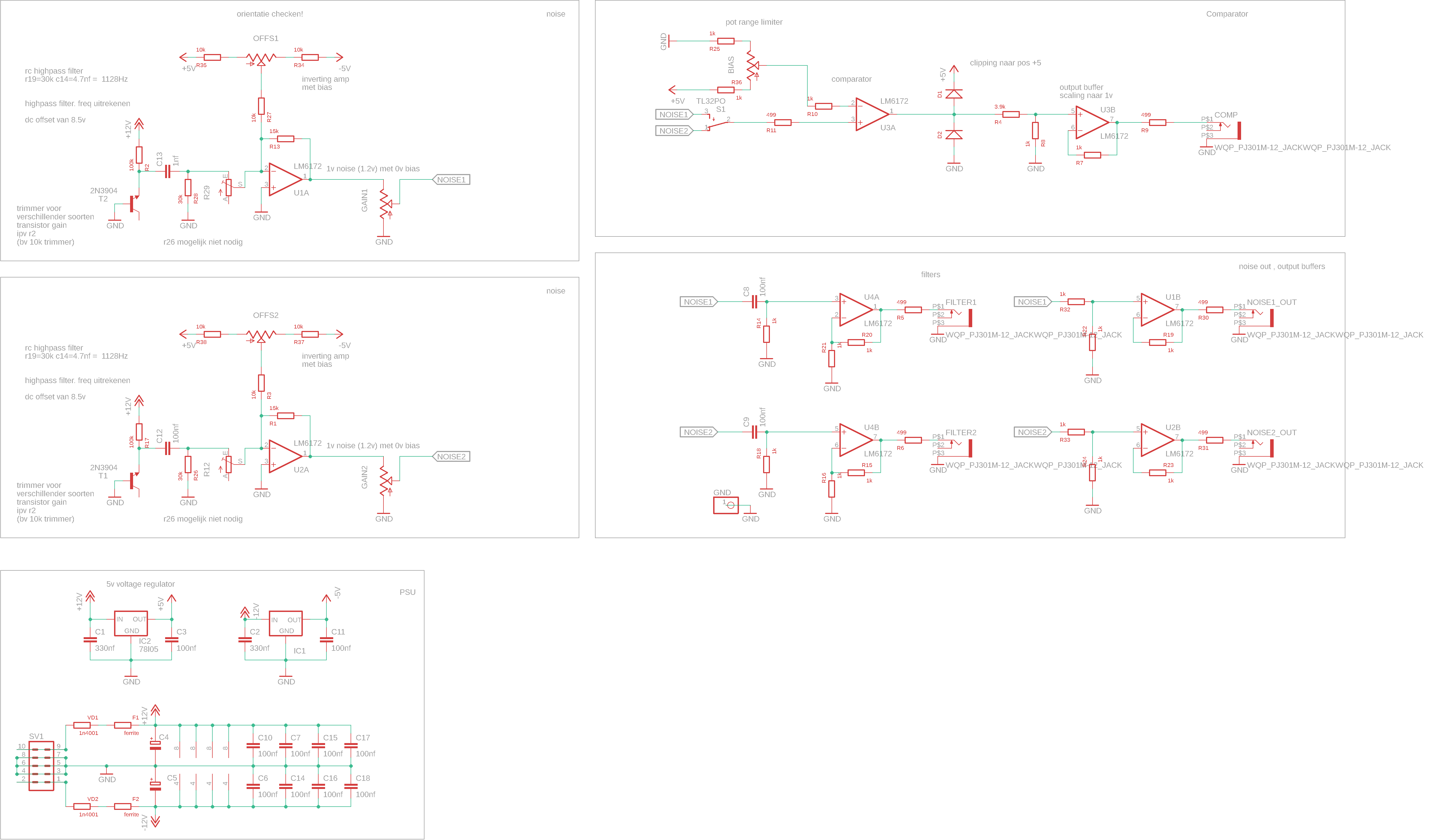
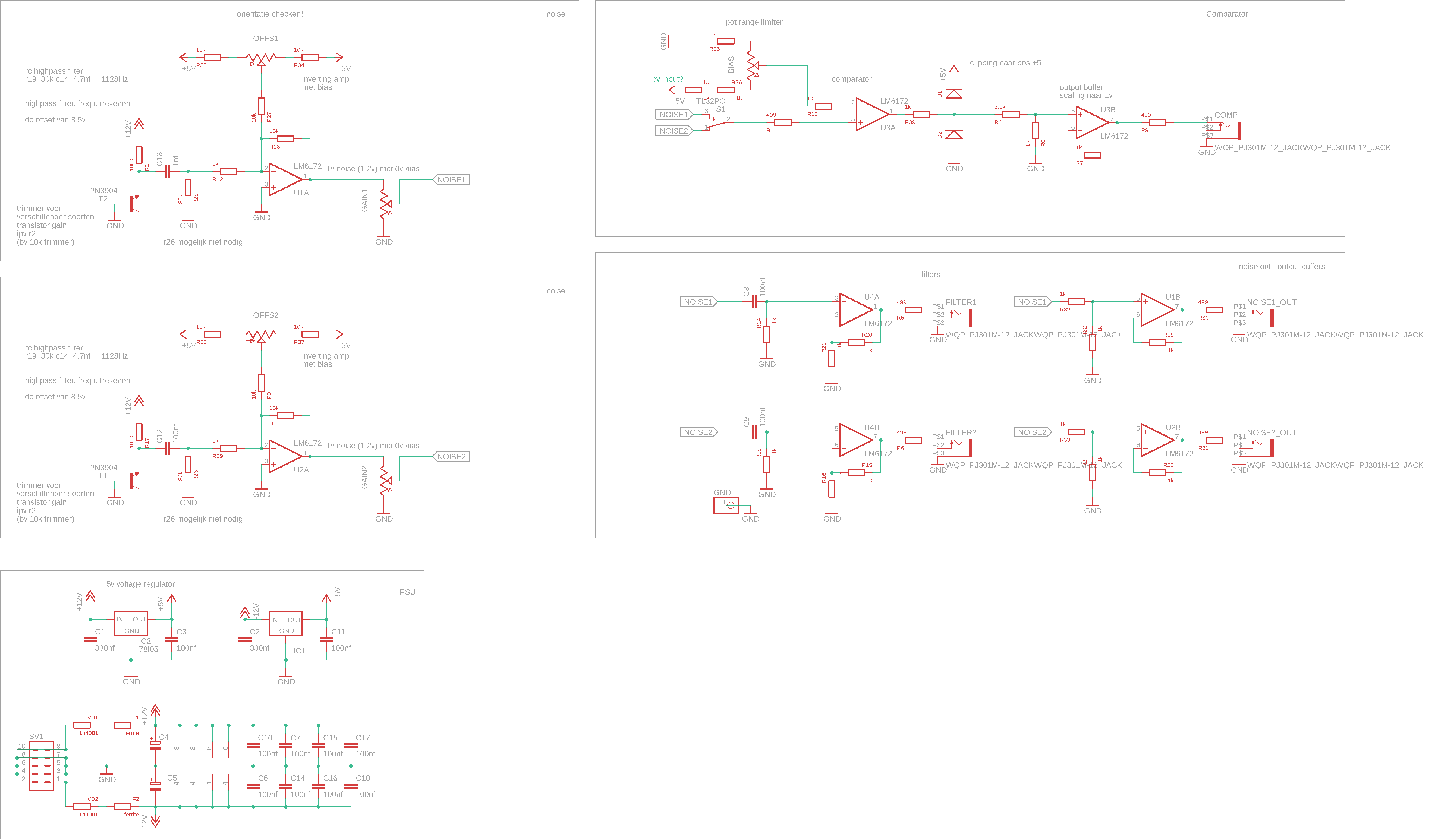
In the current schematic not everything is connected yet and some values and voltages will be changed later. Work in Progress!
Current features:
analog transistor noise
highpass filter
bias control (very rough state, this will be a trimmer on the back)
gain control (now it is just a attenuator)
Upcoming features:
comparator output (possible with CV control over bias)
more outputs with several filter configurations
…and more
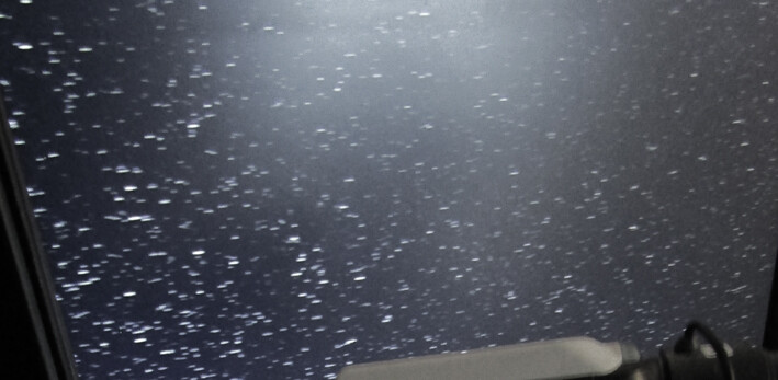
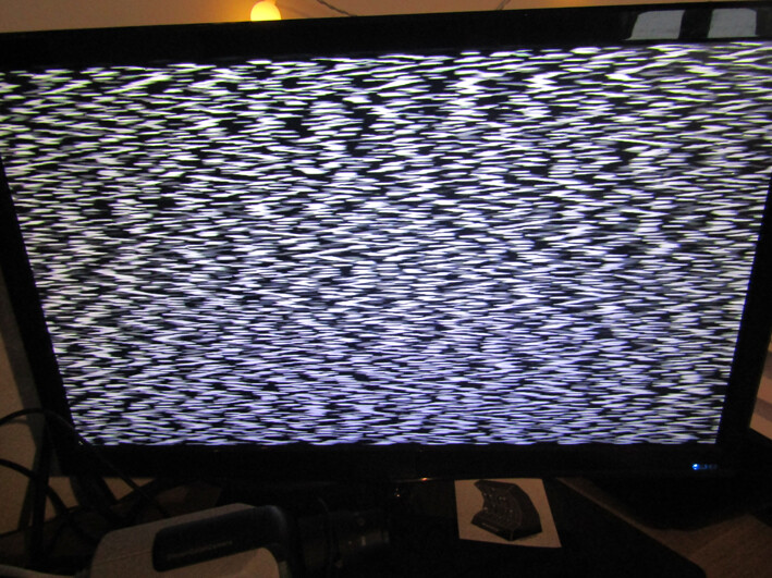
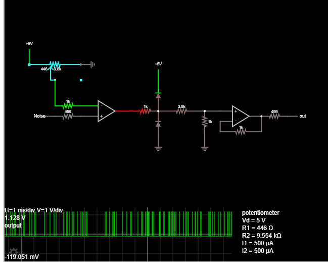
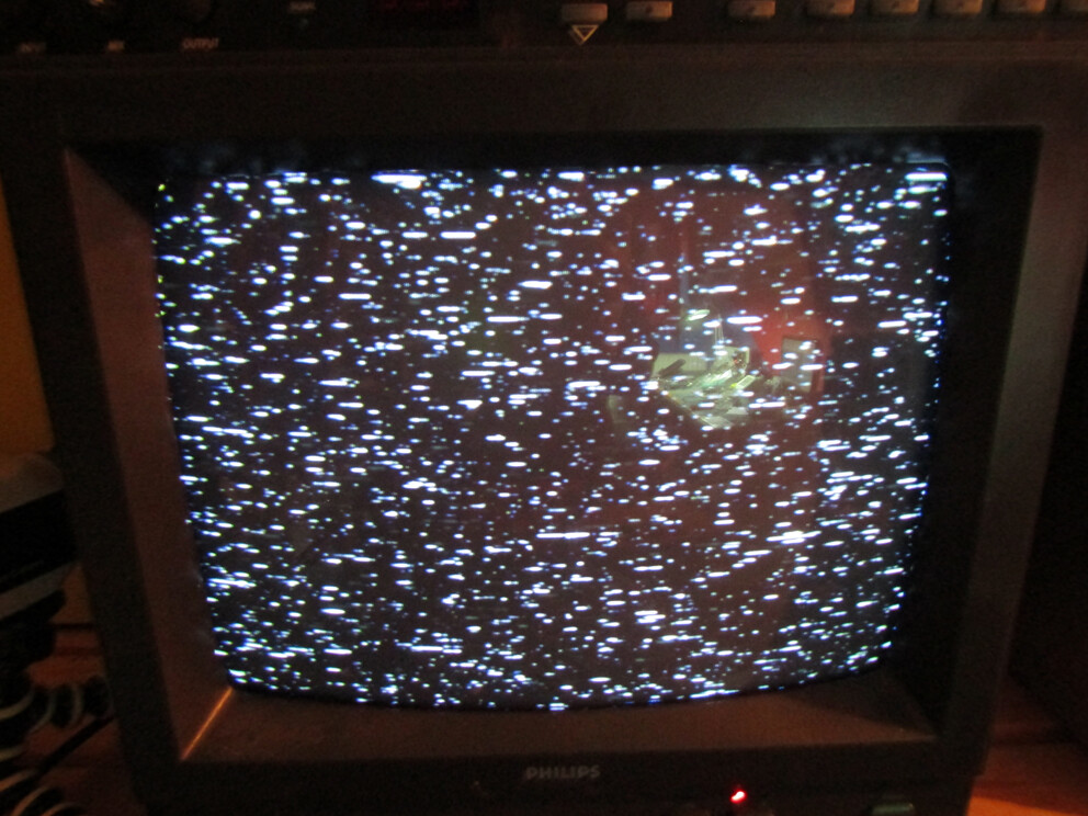
Sunday Noise screenshots:
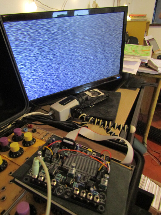
Schematic:
#2 — wednesdayayay · 2020-11-29
awesome noise is always welcome!
I love the idea of multiple filter outputs
#3 — Fox · 2020-11-29
Beat me to it! Very good proof of concept photos.
#4 — Fabong · 2020-11-29
Nice one, don’t think there’s a video noise module available currently so you’ll have the market to yourself for a while

#5 — joem · 2020-11-29
Beat me too… I’ve been meaning to make a simple one of these for a while.
#6 — reverselandfill · 2020-11-29


The Video experimentation board helped me quite a lot. so many of my ideas get stuck in the breadboard stage. It really is helpful to have all those video requirements at hand.
So my Sunday was very productive .
The comparator stage is not working correctly yet . But maybe I have to use a specialized IC instead of this lm6172 setup.
When I patch the noise output to the Cadet Hard Key, it works beautifully. (which uses the LM361)
.
#7 — Temp_hill · 2020-11-29
Really looking forward to something like this!
#8 — Rik_bS · 2020-11-29
Afterlife Laboratories has a noise generator as part of their “Video Motion” module, but it’d be good to see a standalone noise generator on the market
#9 — cburst · 2020-12-01
this looks rad. i appreciate your hard work. will buy if possible.
#10 — reverselandfill · 2020-12-02
It was already snowing here today, so I did some more work on it.
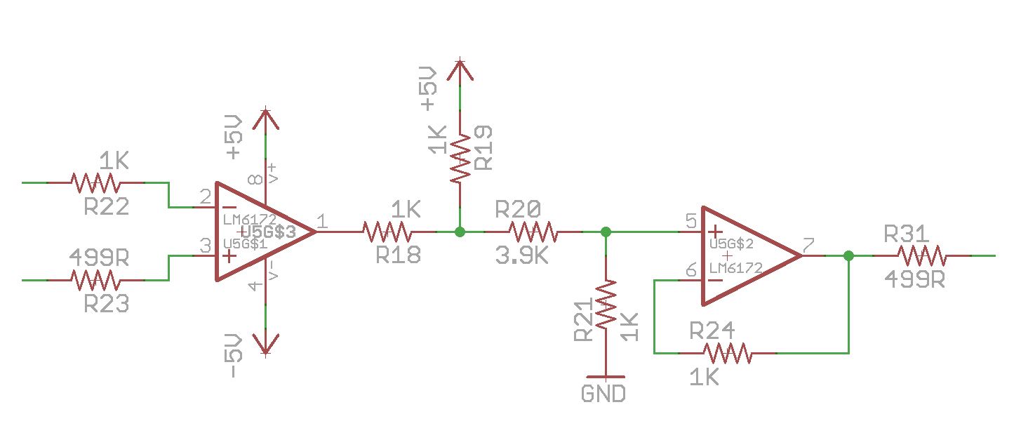
I had some new ideas about the filter sections. to filter after the amplification, and have several configurations. (lowpass, highpass) I still have to test the values, but it will become something like this.
I might make one simple noise source, and later a bigger extended version
This way I can release the first SNOW for the holidays
The simple one will have 2 pots (gain + comparator threshold), 4 output jacks and maybe a switch
*which noise is routed to the comparator. filtered of white. I have to test if this is interesting enough.
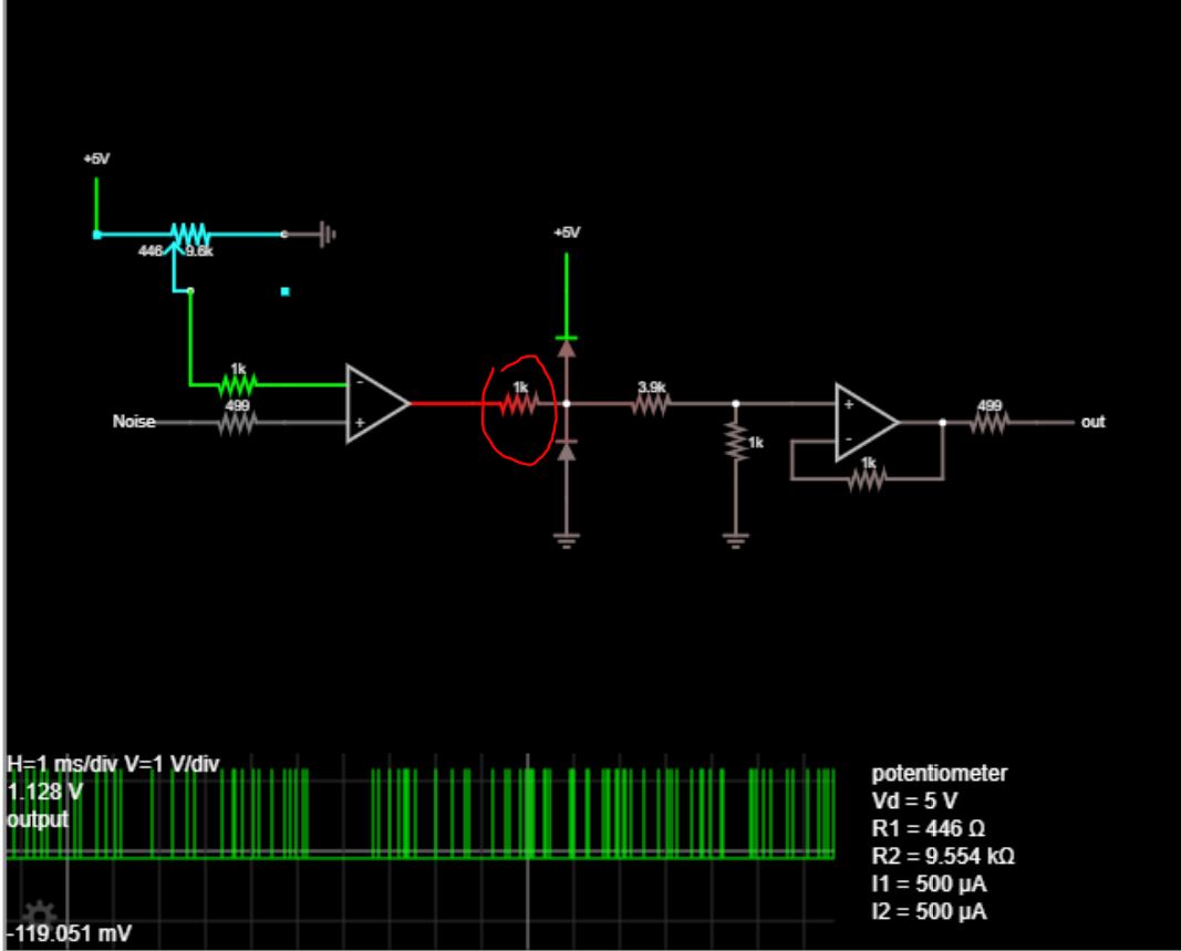
else it may become a jumper setting.The comparator section is working in the simulation:
#11 — Limpasen · 2020-12-03
I want one!
Keep up the good work.
#12 — reverselandfill · 2020-12-03
Update:
I decided to make it a dual noise source. 8HP
That way you can have a low frequency & high frequency noise output at the same time, in my tests this gave interesting results. (snow vs. blizzard)
Features:
2x offset pot
2x level pot
1x comparator pot
1x comparator source switch (noise1 or noise2)
2x noise out jacks
2x filtered out jacks (2x highpass filters with gain settings)
1x comparator out jack
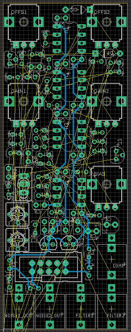
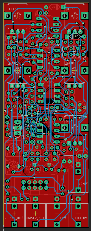
Unrouted pcb:
All resistors are vertical. another tight fit!
there are 2x trimpots for the noise gain, as this might vary per type of transistor. I use 2n3904.
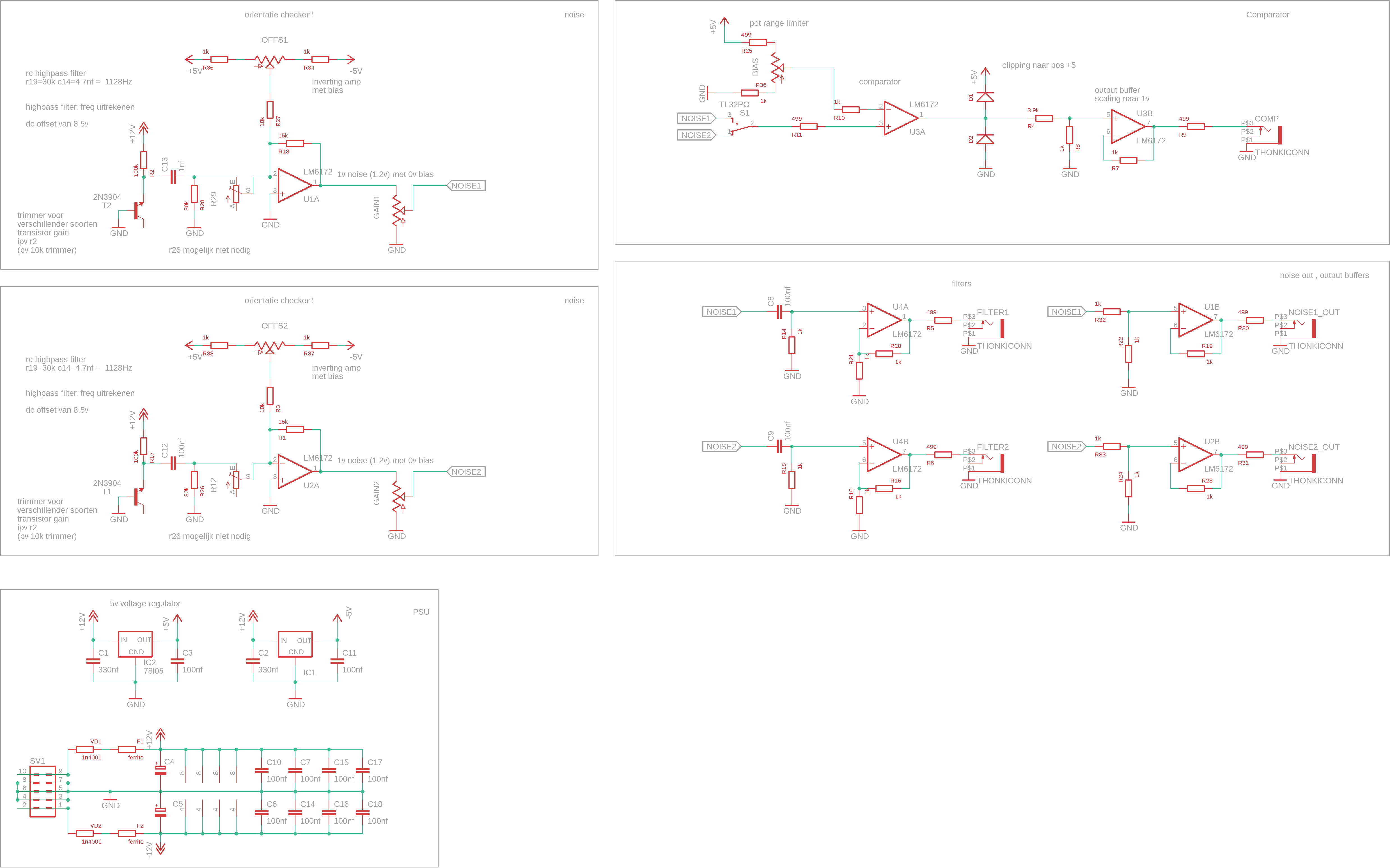
Big schematic proto:
Filter values are not yet defined. some resistors may be added / deleted after tests
#13 — wednesdayayay · 2020-12-03
wow this is going to be a beast of a module!
glad to see some comparators in the mix for sure.
I liked war of the ants but it was a bit expensive and large for what I wanted out of a noise source. This feels more in line with what I’m looking for.
#14 — reverselandfill · 2020-12-03
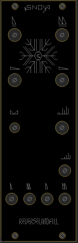
Working on the panel!
#15 — vhsdestroyer · 2020-12-03
Gonna have to get me one of these. Are you gonna do the pane red or black?
#16 — reverselandfill · 2020-12-03
I think black might be better in this case. but I’m not sure yet
black / white is also how the output should look. black skies snow storm
#17 — rempesm · 2020-12-03
I’d love to see this one as a black panel–makes sense with the function of the module, too.

#18 — vhsdestroyer · 2020-12-03
I would definitely love a black panel on this
#19 — reverselandfill · 2020-12-03
yes, black panel it is!
#20 — VanTa · 2020-12-04
Amazing!
Count me in!
3 filters would be even crazier, to send the related outputs to RGB channels.
Another idea: jumper after either noise1 or noise2 and before the switch to use an external signal on the filters with an expansion panel
#21 — reverselandfill · 2020-12-04
I think I will make a dedicated filter module for that (am working on that already)
The jumper pads are a good idea. I’ll add that!
I have to add some test / reference pads anyway, for the trimmer adjustments
This analog noise is very interesting. I will keep working on it. A version with more options will follow!
I also want to add digital noise, which looks totally different and useful too!
#22 — Robbertunist · 2020-12-04
We can do a group order for the Berlin heads who are interested


@horacio2222@destroythings@cyberboy666
#23 — reverselandfill · 2020-12-04
I just ordered the boards (black pcb & panel)
We’ll see if they are bug-free.

#24 — Gavin · 2020-12-04
Is this related to the noise v8? On your post about using that for video I really loved how the range jumpers produced this thick blocky noise from low frequency ( 00.51 on https://vimeo.com/438658284 ). Is that the low frequency 2nd noise on this one?
#25 — reverselandfill · 2020-12-04
no, this one is new!
(analog noise vs digital, like I hinted above)
I will make the Noise v8 - video convertion later.
#26 — VanTa · 2020-12-05
Microcontroller based for the digital noise section?
It will be cool to be able to program your own noises
There’s already some really nice perlin noise libraries. I could help with that.
#27 — destroythings · 2020-12-05
Yes i’m in for one if you wanna sort out a group order.
#28 — brownshoesonly · 2020-12-06
What frequency does this operate at? Is it a MHz noise source?
#29 — VisibleSignals · 2020-12-06
Hi Dave!
Based on the length of the short white lines in the screen snapshots Martijn included at the top of this post it looks to me like it’s effectively in the low MHz range. The circuit schematic is also there - basically a transistor with unconnected collector (like the 2N2172 audio noise sources that used to be all the rage back in the day - see also http://musicfromouterspace.com/analogsynth_new/NOISECORNREV01/NOISECORNREV01.php for Ray Wilson’s audio noise source, basically the same thing but lower bandwidth.)
When I get my board for this I’m going to try a few different transistors (I have several boxes full of obscure ones) and see what sort of variations I can coax out of it.
#30 — transistorcat · 2020-12-07
Looking forward to this one.
Based on the pictures I do wish it could get even further into the pure snow region though.
In your pictures, do you know what the first-stage gain trimpot was set to?
(I suspect you may be losing some high-end to the Gain-bandwidth of the amp)
#31 — reverselandfill · 2020-12-07
correct.
The first pictures are just the first experiments.
with adjustments to the highpass filter caps , higher frequencies are reachable. (I got very snowy results!)
I’ll find the best values and make a MOD guide when the pcb is tested and ready.
#32 — reverselandfill · 2020-12-14
The PCBs came in today!
I’ll start soldering tomorrow
#33 — vhsdestroyer · 2020-12-14
Are there gonna be any kits available or will these all be completed modules?
#34 — jwsmithwick1 · 2020-12-14
Please count me in for an assembled snow module.
#35 — rempesm · 2020-12-15
Mark me down for one PCB/panel set, too. If you have anything else in the works, happy to wait until the next one gets released to save a bit with higher shipping costs.
#36 — Robbertunist · 2020-12-15
Update:
I tagged a few of the Berlin heads but forgot I’d already done it a couple of weeks ago in this thread

Old post:
Anyone in Berlin wants to build this new noise module if Martijn gives the thumbs up tomorrow or the day after? We can split the shipping costs.
Deleted the tags.
#37 — reverselandfill · 2020-12-15
@vhsdestroyer: pcbs, kits and build modules!
@Robbertunist: I’m still in quarantaine for a week or so, this means that I will start with the orders after that.
When the module is tested OK, I’ll start an order thread!
#38 — Robbertunist · 2020-12-15
Stay safe & healthy Martijn
Definitely no rush as there’s no deadlines regarding gigs & such atm 
#39 — reverselandfill · 2020-12-15
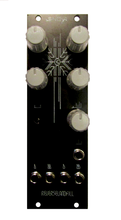
test build one. the excitement before plugging it in!
(I don’t have the correct switch, so there is a hole
I installed a jumperheader.
#40 — reverselandfill · 2020-12-16
I made a dumb mistake on the pcb. I’ll keep testing to see if I can fix this easily. else I’ll reorder the pcb’s.
prototypes
#41 — VisibleSignals · 2020-12-16
I know exactly how you feel… I keep a bunch of unusable PCBs (too many kludges required) on hand to remind myself not to made the mistake of ordering more than the minimum number of PCBs for untested prototypes
#42 — Robbertunist · 2020-12-17
Ughh, that’s got to hurt

Hopefully you can find an easy work around & haven’t ordered too many of them.
#43 — reverselandfill · 2020-12-30
I made some some progress. traced the bug and cut the copper.
There is noise output now. SO I’m going to check the rest of the circuit.
I had some new ideas about the filters, so I might add those, we’ll see
#44 — reverselandfill · 2021-01-07
Most outputs work, except for the comparator output.
I will work on that. The 1st prototype worked, so it is probably something easy to fix
the noise range is pretty nice, lots of cool textures !
#45 — Fox · 2021-01-07
Do you have an updated schematic to look at?
It looks like you have +12V connected to the input of your 7905 regulator. Negative in, negative out.
Also, for the diode clipper portion to work effectively, there needs to be a resistance before the diodes.
#46 — Spacenoodle · 2021-01-07
Forgive my ignorance, but I’m curious if this noise overlaps audio/sub ranges in a useful way. My system has become a hybrid of audio and video - it’s great to be able to swap modules for such different uses and I’m often looking for these opportunities.
#47 — reverselandfill · 2021-01-08
yes, that 7905 thing was the bug
stupid
I’ll look into the diode tip, thanks … The simulation worked, but reality is different 
#48 — reverselandfill · 2021-01-08
I have not listened to it yet. The output is about 1v, so you would need to amplify it to audio levels
You can set the frequencies of the filters by the resistor + capacitor, so it would be possible to scale that to audio ranges. I’ll make a note of this when I write the buildguide
The offset knobs won’t give you useful audio results though.
#49 — Fox · 2021-01-08
reverselandfill wrote:
I’ll look into the diode tip, thanks … The simulation worked, but reality is different
Your simulation has the resistor between the op amp and diodes, but your schematic doesn’t.
Without a resistor, the full current from the op amp conducts across the diode. I think diodes in this situation may even “latch up” but I have to read more about that.
What kind of signal are you seeing with the current schematic? Hotter than 0/+1v? DC?
There is another option to consider which doesn’t use diodes. This requires you power that LM6172 with +/-5v and add a few resistors at the output. Ideally the output bounces between -5v and +5v. R18 and R19 create a voltage divider when the op amp outputs -5v only. So the junction between R18 and R19 will only be 0v and +5v.
This is effective, but has one drawback. The op amp will not output exactly -5v and +5v, but will instead be closer to -3.35v and +4.14v (according to my simulation in LTspice). So the final output will be +140mV to +840mV with these resistor values. While this is not “full” brightness, these voltages ‘will’ at least trigger comparators that use a reference of 500mV like much of the Castle series.
I think if you want a full-brightness digital noise output that clips at exactly 0/+1v, you may need to use the more precise clipper circuit you see in Cadet II.
Would you mind cutting/adding in the resistor here and let us know if you see better results?
#50 — reverselandfill · 2021-01-08
I should have looked to my simulation better !
Thanks for the detailed advice. I will do some more testing after the weekend and report back here.
The comparator jack has no output on my CRT, I’ll check again with scope for precise measurements
#51 — reverselandfill · 2021-01-13
I ordered a new prototype with these fixes.
#52 — reverselandfill · 2021-01-25
the pcbs are in. I’ll start testing this week!
#53 — reverselandfill · 2021-01-28
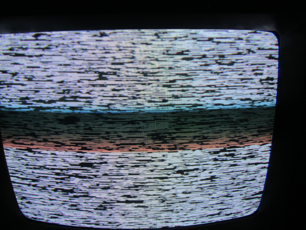
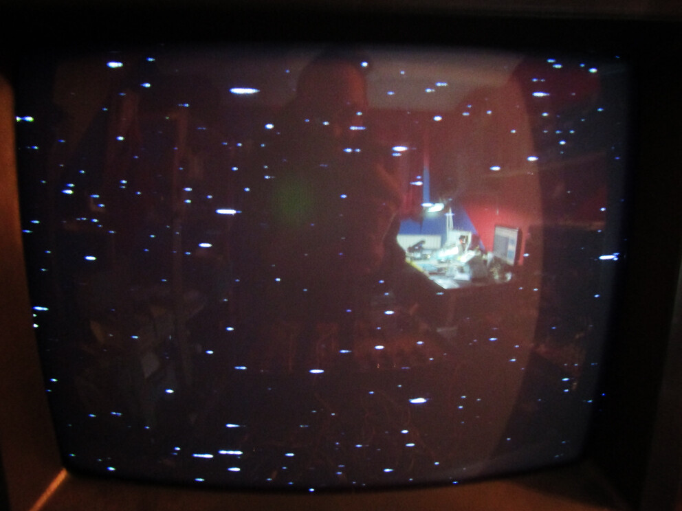
test update:
the comparator works very good!
it can go from black starfield to white blizzard, so it lives up to its name!
channel 2 noise looks nice
I have to adjust some values for amplification settings (channel 1)
The values I calculated for filters might be off, so I’m going to test what works better!
quick and dirty screen photos of the comparator out:
#55 — wednesdayayay · 2021-01-28
this is looking lovely!
#56 — jsonpayload · 2021-02-02
This looks sweet! Nice use of 8hp
#57 — reverselandfill · 2021-02-02
OK testing is done!
Turned out I had a faulty lm6172 in my testbuild. replaced it and now everything works as intended!!

I’ll make a [ORDER] thread. I have about 8 pcbs left, I’ll order more this week!
I’ll try to make a demo soon!