[ORDER] SHUTTER - Triple Video Rate Mux
Category: Unknown · Tags: — · Posts: 92
#1 — Fox · 2021-03-08

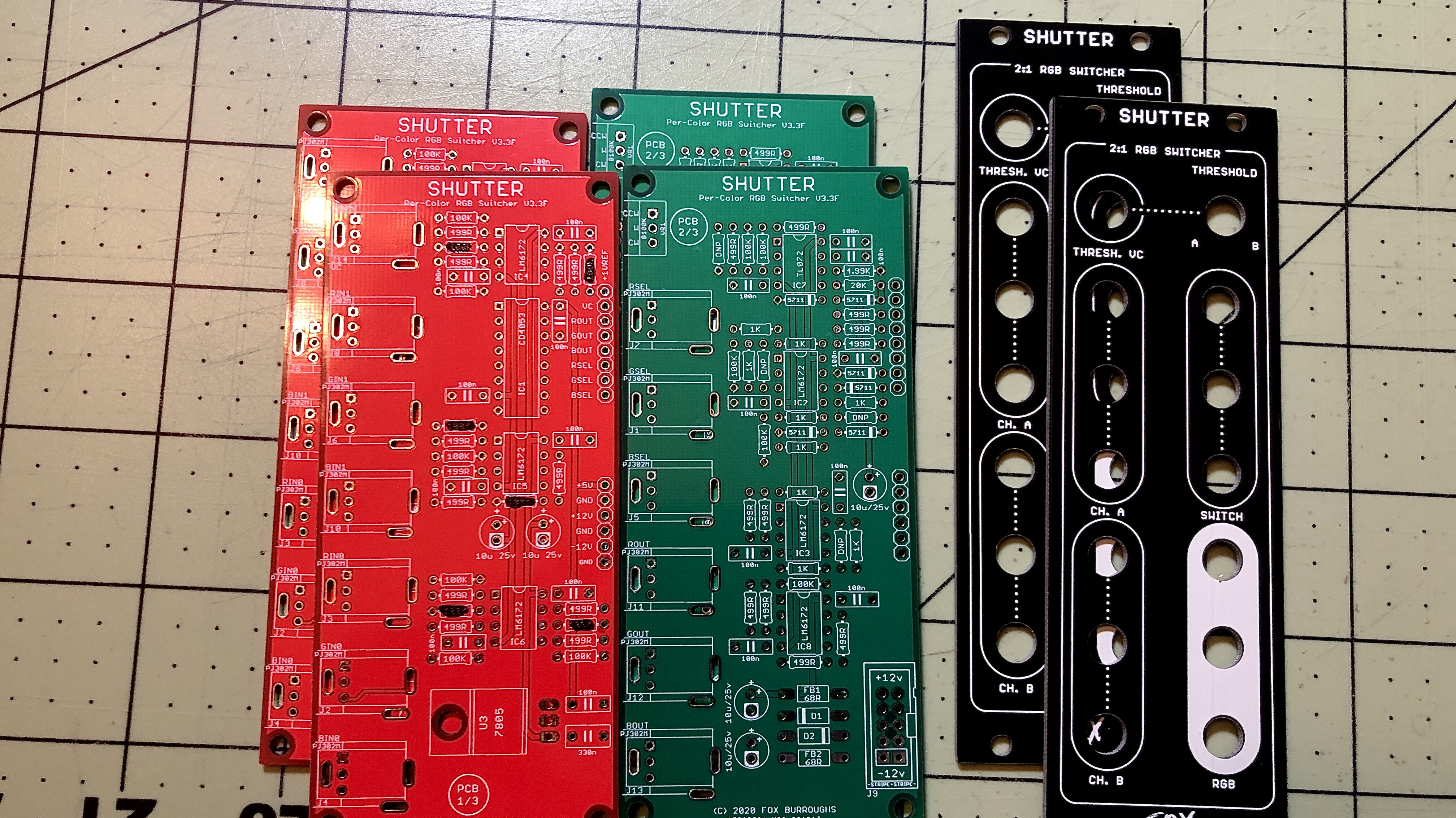
SHUTTER has been finalized and I can start shipping DIY PCB panels.
Complete Modules may be preordered and will be built together.Description:
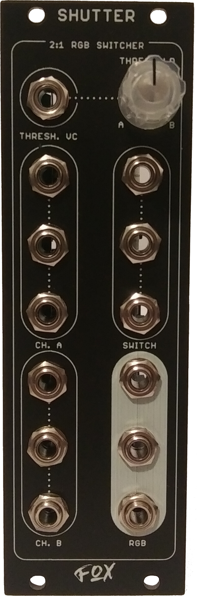
SHUTTER is a Video Rate, Triple Luma Switcher which allows users to switch Luma signals based on the brightness difference of the Switcher inputs.
Three sets of 2-to-1 multiplexer circuits are provided which allows users to switch two full color RGB-sets, or six different B/W images independently.
Multiple SHUTTER modules may be daisy-chained to switch between more than 2-RGB sets.
- ?? mA +12V
- ?? mA -12V
- 0 mA 5V
- 8HP wide
- 49.53 mm deep
CH A. & CH. B inputs: +5v/-12v tolerant
Thresh VC, Switch inputs: +12v/-12v tolerant
Prices:
DIY PCB Set: 32 USD
Built Module: 163 USD
US Shipping: 4 USD
Note: SHUTTER switches at video rates. For best results, it is required that users have a low noise power supply and avoid sub frame-rate signals on the “switcher” inputs. Examples were created using Malekko Power and Tiptop Studio Buses along with many LZX modules. Further patch notes and Build Guide can be found below.
PCB/Panel set Orders:
Please respond or PM me to place an order. @reverselandfill - 1x PCB set - Shipped @allthesixes666 - 2x PCB set - Shipped @omiindustriies - 1x PCB set - Shipped @everyoneismyfriend - 2x PCB set - Shipped
mrfang - 2x PCB set - Shipped
dr_how - 1x PCB set - Shipped
Dewb - 1x PCB set - Shipped
RoseColouredGlasses - 2x PCB set - Shipped
Midcitysteve - 1x Shutter - Shipped
Jesse - 2x PCB set - Shipped
Makaiya - 2x PCB set - PM’d
voidevaqion - 1x PCB set - PM’d
Mattzog - 1x PCB - Shipped
droningbrightnessav - 1x PCB - Shipped
sebiiksbcs - 1x PCB - ShippedBuilt Module Orders: @TrashTeam - 1x Built Module - Ordered @Maytoast - 1x Built Module - Ordered
jwsmithwick1 - 2x Built Module - Ordered @DesertMuseum - 2x Built Module - Ordered @IoDionysus - 2x Built Module - Ordered @jsonpayload - 1x Built Module - PM’d
Dora - 1x Built Module - Ordered
brendanleespengler - 1x Built Module - PM’d
Video.pls - 1x Built Module - Ordered
#2 — Fox · 2021-03-08
All examples patched and recorded by @rempesm
Without him, this wouldn’t be possible.

https://www.youtube.com/watch?v=rVBkoDEr9X4
https://www.youtube.com/watch?v=iBXgWNuTpmg
https://www.youtube.com/watch?v=HRmYEEpNJTk
https://www.youtube.com/watch?v=6a4wg_imjgY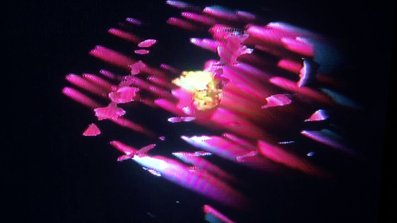
https://www.youtube.com/watch?v=Qc4gO7M78Sk> This (above) is using the same still just processed two different ways into the RGB inputs of Ch. A & B. The Y from one still (the smeared to the right one) goes into the VC Threshold input. I’m using a modulated Prismatic Ray into the R Switch input (nothing plugged into G or B Switch). The modulation into Prismatic Ray is a mish mash of the Y from the second still, Diver, and an LFO.

https://www.youtube.com/watch?v=3eGksva8cnc Advanced Patching with Multiple SHUTTER moduleshttps://www.youtube.com/watch?v=Zi_UCNHx9PQ
This is 4 separate images being fed across 3 Shutters and I’m using the Y from each of them to alternately switch the next Shutter’s R Switch input.
Examples of glitches and how to to Avoid (or not)coming soon. I just have to keep the thread editable until then.
#3 — Fox · 2021-03-08
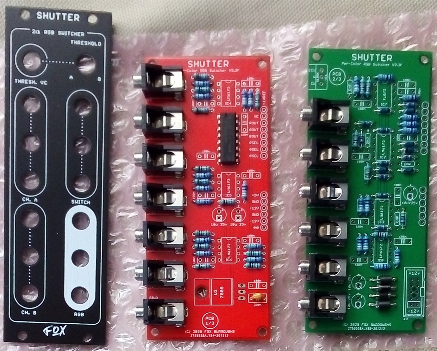
SHUTTER
BOM and Build Guide
Expand for BOMQtyValueParts1330nF capacitorC1510uF 25v Electrolytic CapacitorC2, C6, C23, C24, C2618100nF capacitorC3, C4, C5, C7, C8, C9, C10, C11, C12, C13, C14, C15, C16, C17, C18, C19, C20, C2121N4001D1, D261N5711D5, D6, D7, D8, D9, D10268R Ferrite BeadFB1, FB21CD4053IC16LM6172IC2, IC3, IC4, IC5, IC6, IC81TL072IC713PJ302M JackJ1 - J8, J10 - J1412x5 (10-pin) male headerJ911100K resistorR1, R2, R3, R4, R5, R6, R30, R31, R32, R48, R51120K resistorR2814.99K resistorR2991K resistorR33, R34, R35, R36, R37, R38, R39, R40, R4123499R resistorR7, R8, R9, R10, R11, R12, R13, R14, R15, R16, R17, R18, R19, R20, R21, R42, R43, R44, R45, R46, R47, R49, R5017805U31B100K potentiometerVR116-pin stackable header-18-pin stackable header-1single row, pin header-1T18 Davies Knob-Other Notes:
(1) IC1 must be CD4053 as 74HC4053 and others may not be compatible with the supply voltage.
(2) VR1 is a Linear 100kOhm pot, unlike the typical 10kOhm pot used in most DIY projects.
(3) D1 & D2 can be replaced with similar diodes, for example: 1N4002, 1N4004, 1N5189, etc.
(4) If you wish to use ribbon cable rather than stackable headers, you may. It is more difficult to prepare the wire than it is to use sleek headers.
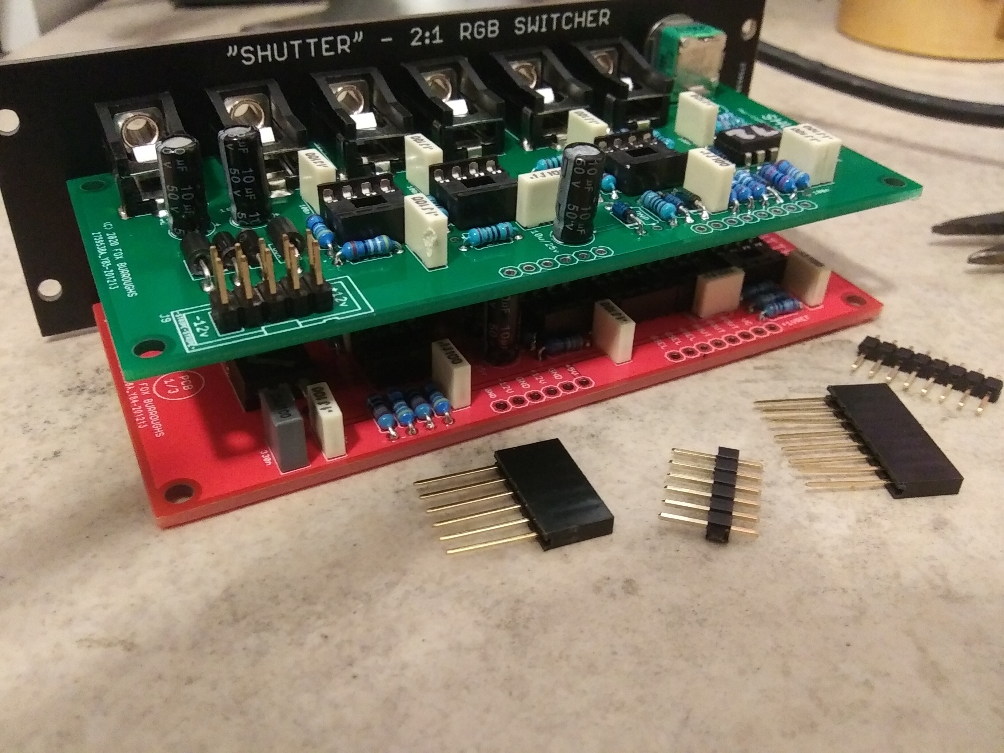
All build photos present, text tutorial being added soon.
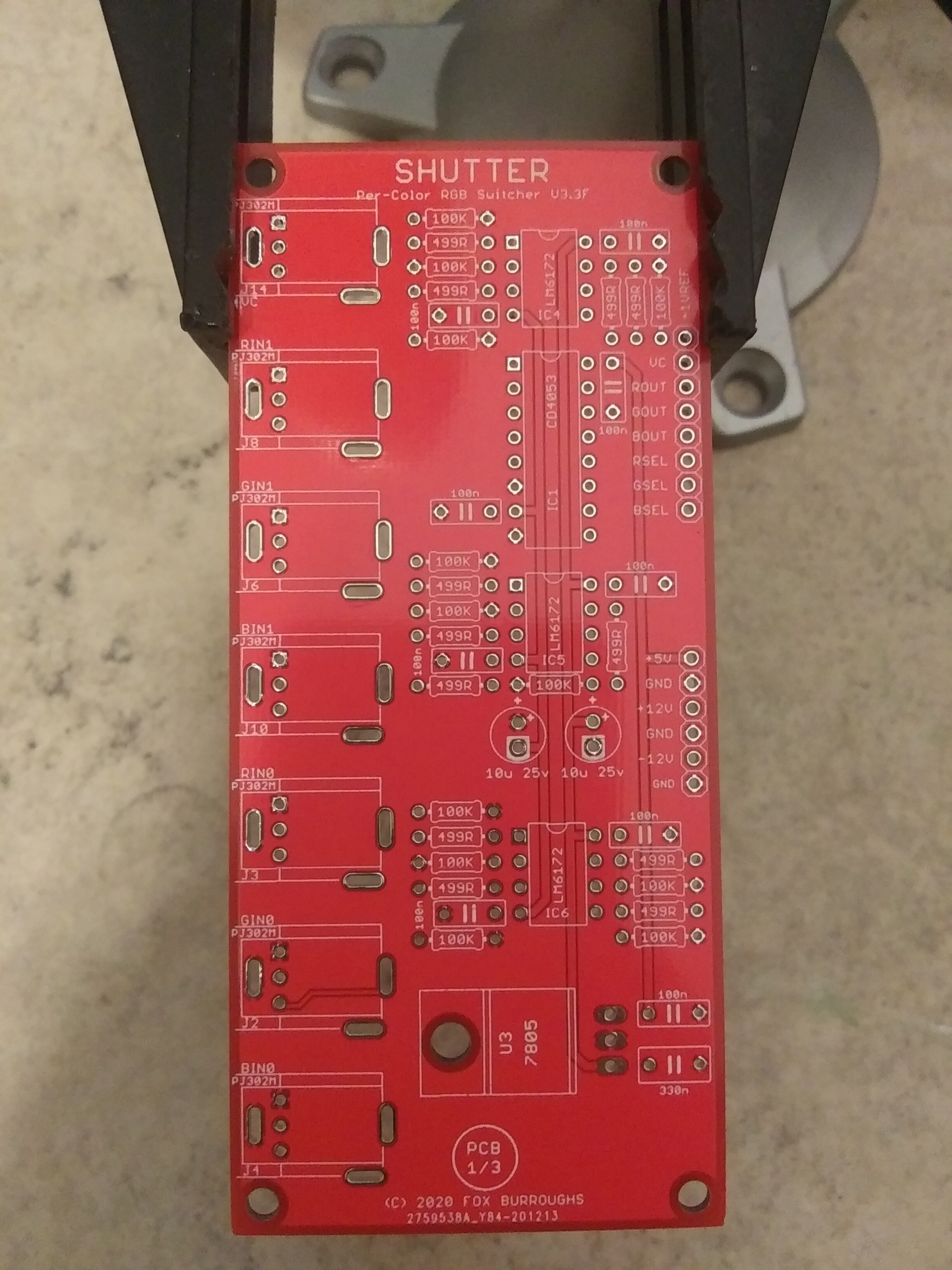
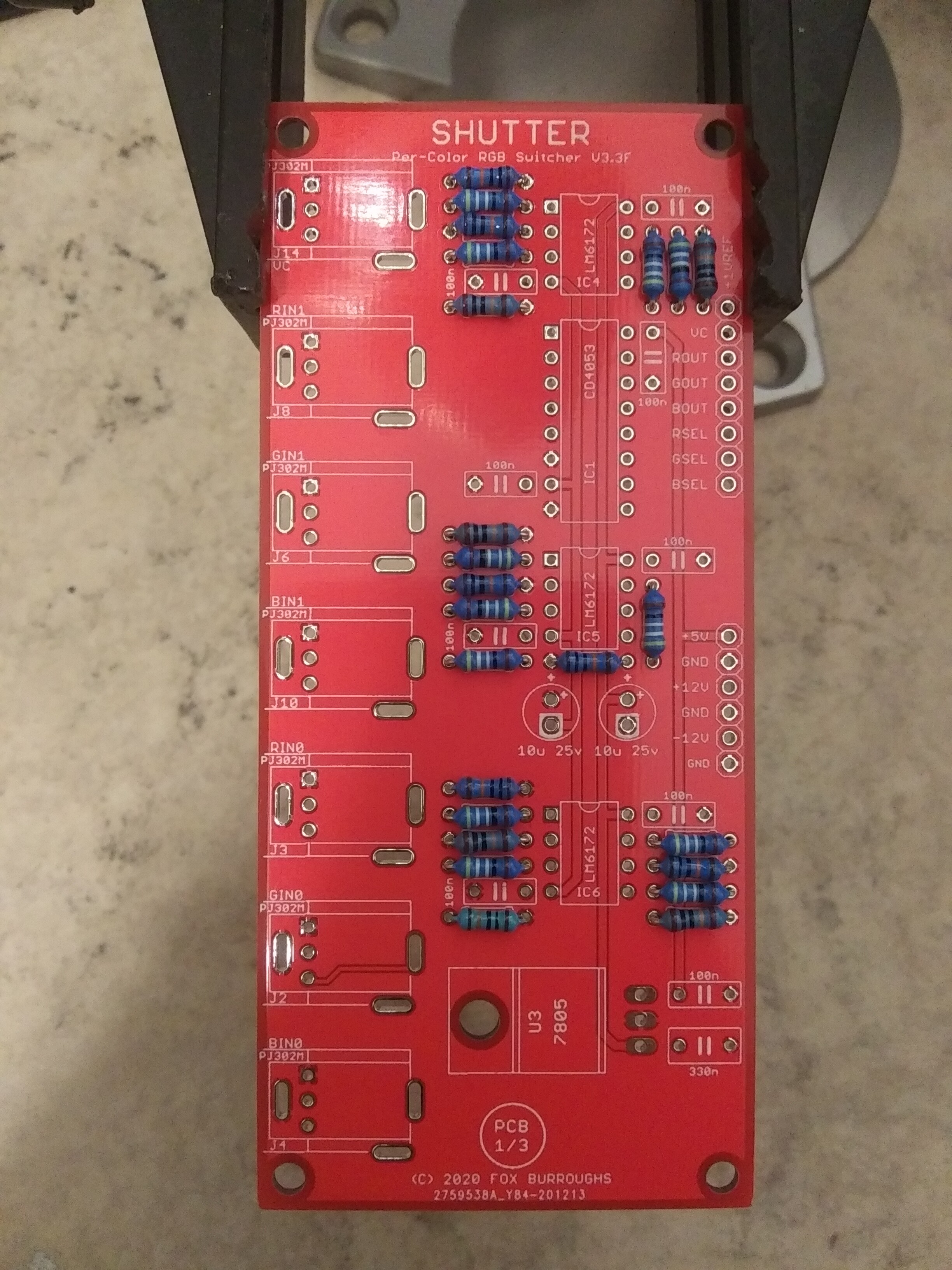
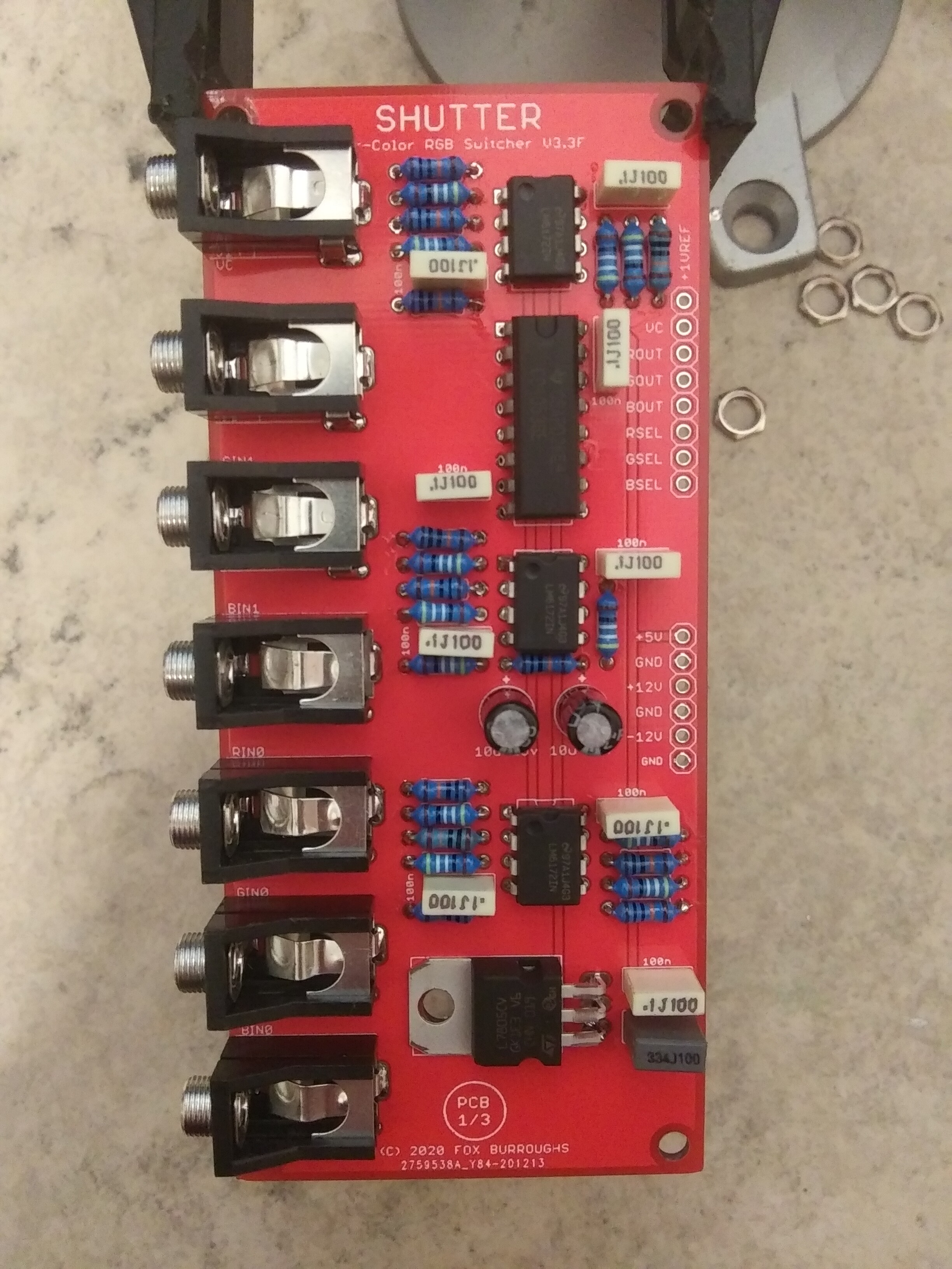
Expand for Build Guide Part 1Start with (PCB1/3). Populate shortest parts first.
All values are listed on PCB for ease of locating.
Step 1:
499R, 1K, 100K resistors
Step 2:
High Speed Diodes, Protection Diodes and Beads
Please take special note of the diode polarity
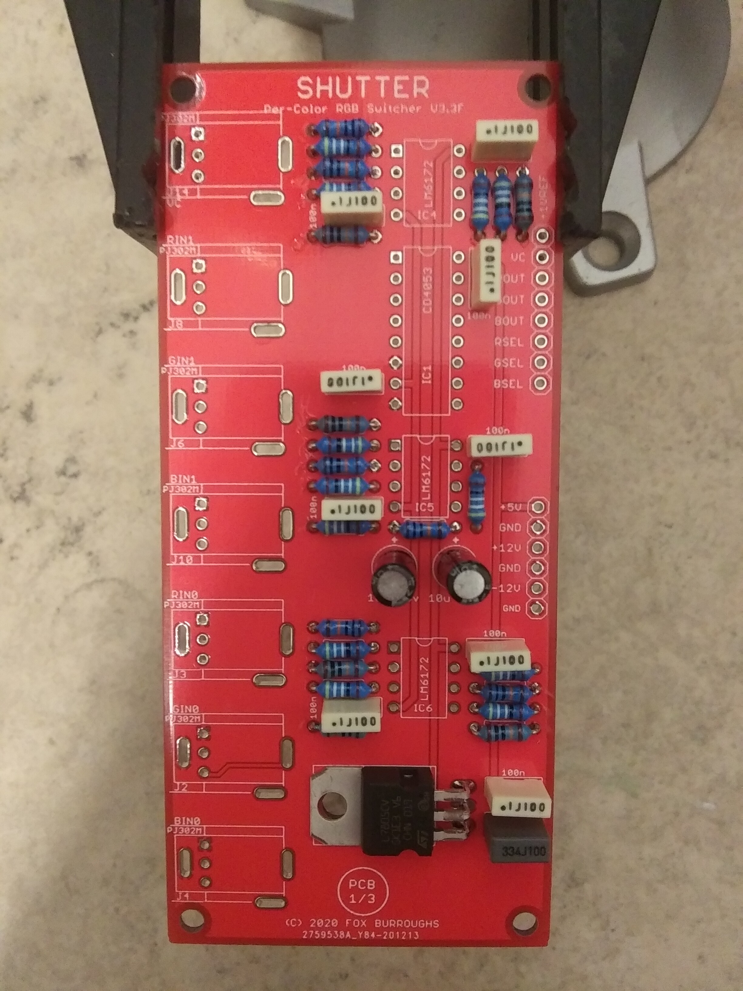
Step 3:
Optional Sockets, electrolytic capacitors.
You may skip sockets for your IC’s.
Take special not of the polarity of the electrolytic capacitors; negative goes to the white-outlined hole.
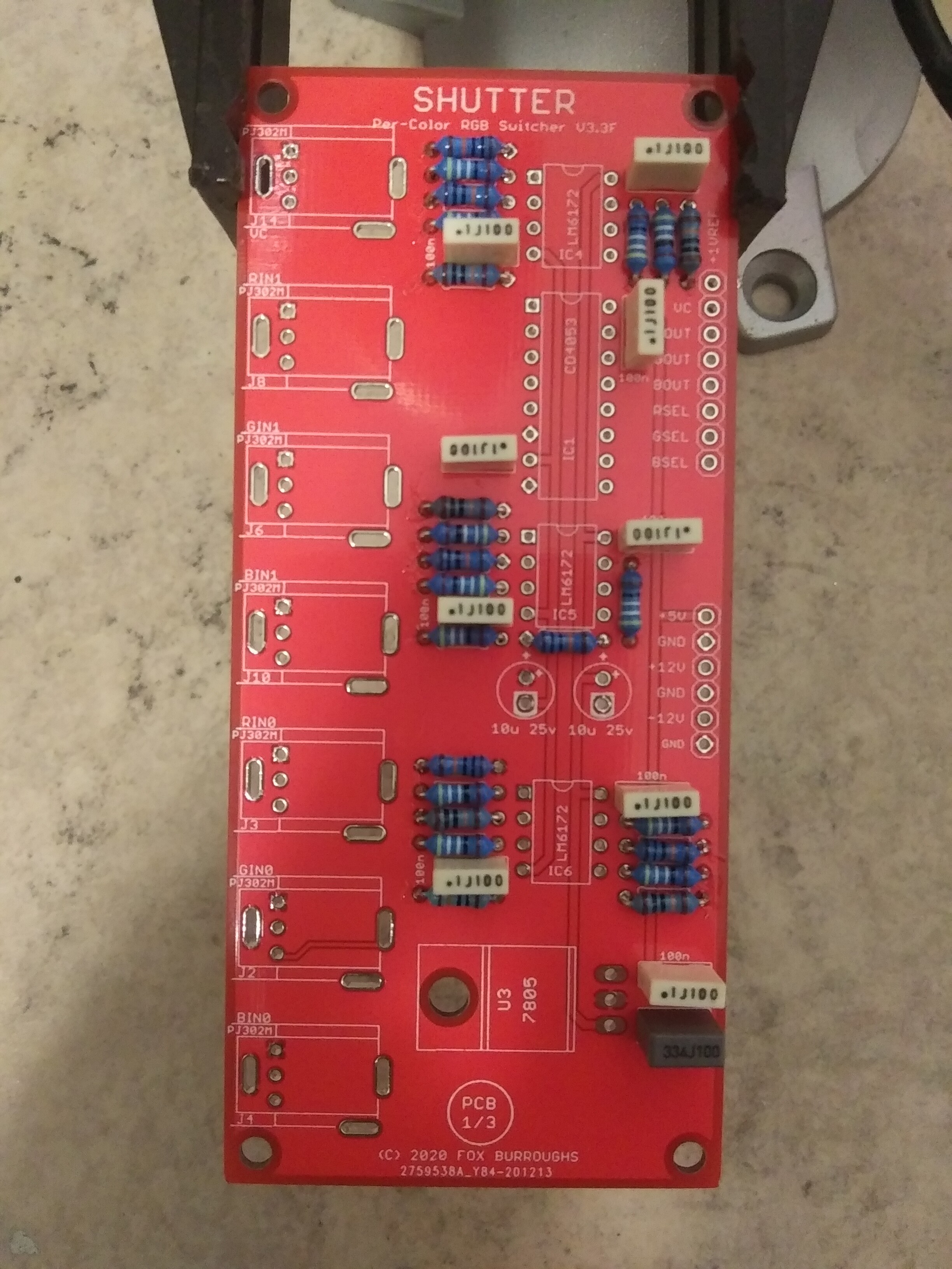
Step 4:
Decoupling capacitors
Use either ceramic, or film box caps; which ever you prefer.
Step 5:
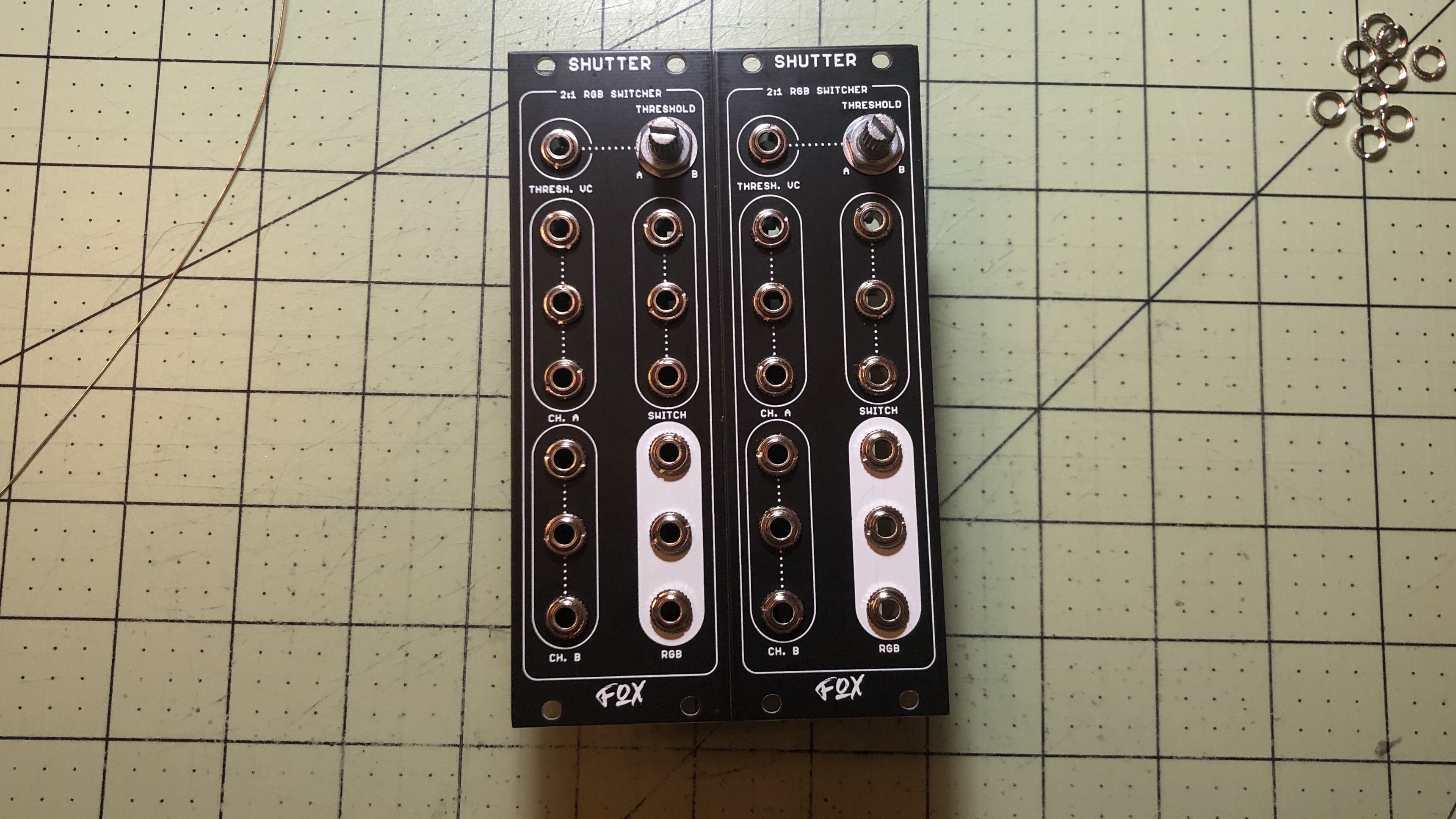
Jacks and Pot
Place all 6 jacks and pot into the board but do not solder them yet.
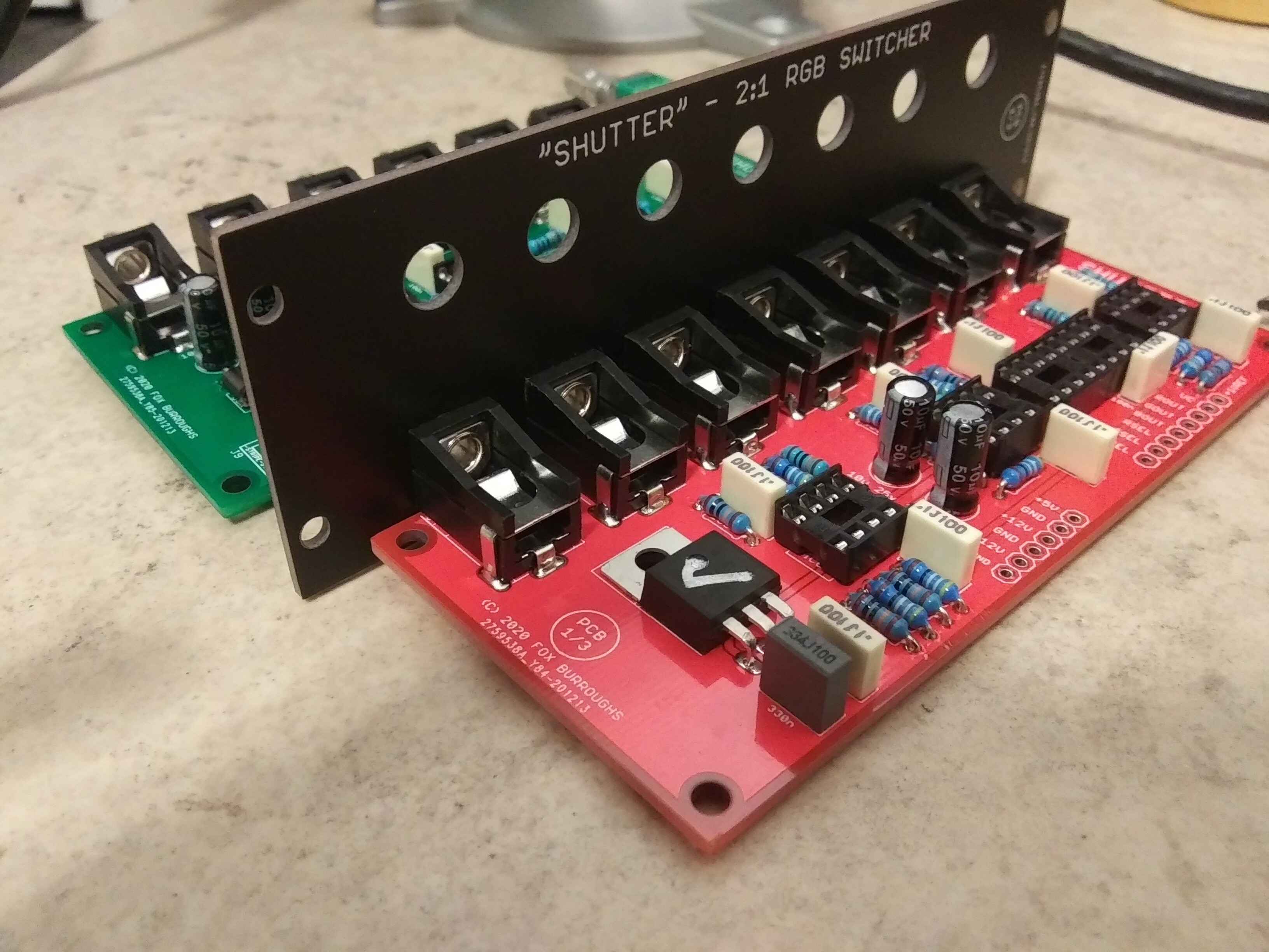
Next, mount the PCB onto the faceplate and finger-tighten the nuts for all 6 jacks and pot. Once they are all straight, then you may solder them. Remove the faceplate and move on to (PCB 2/3).
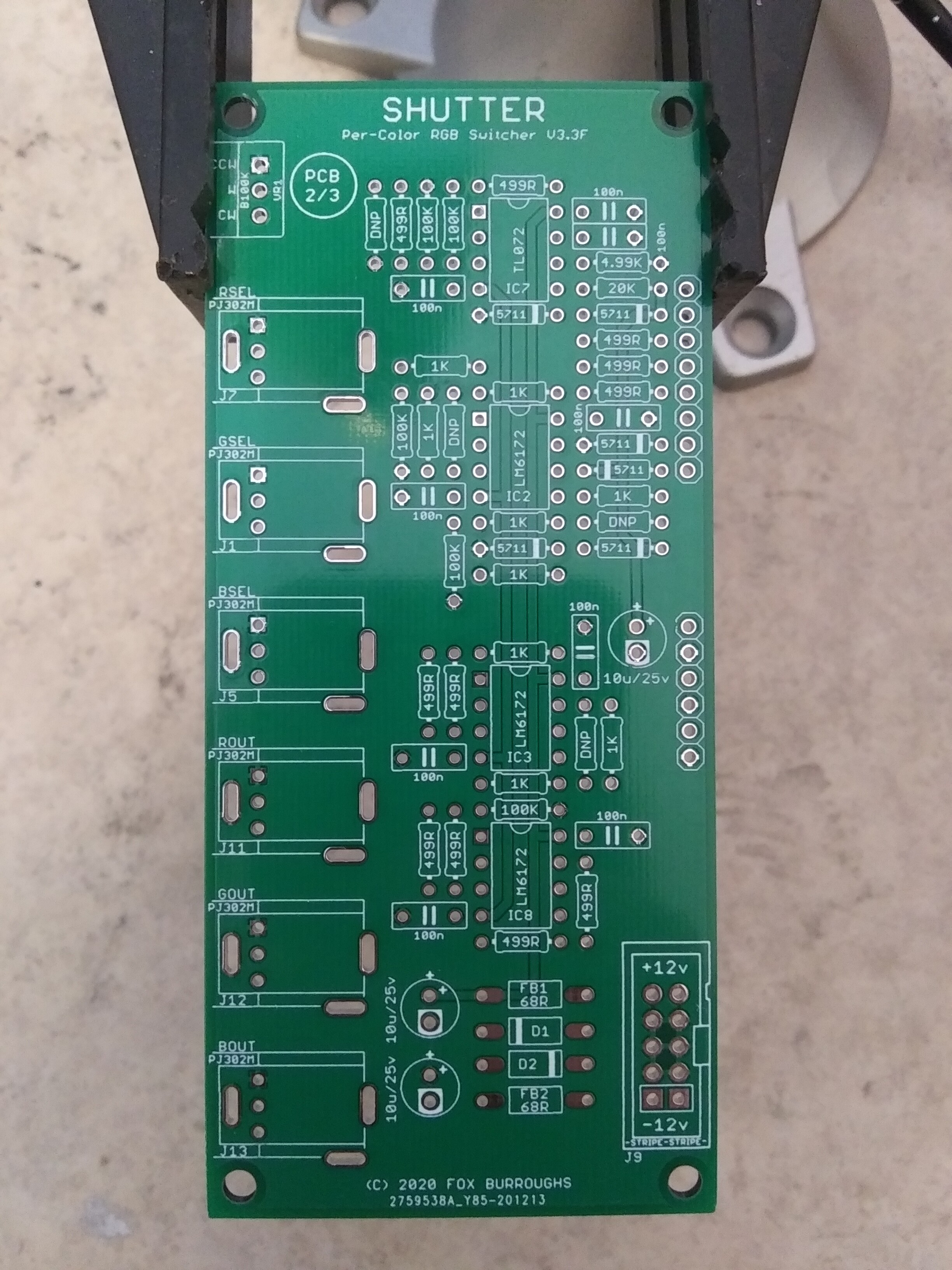
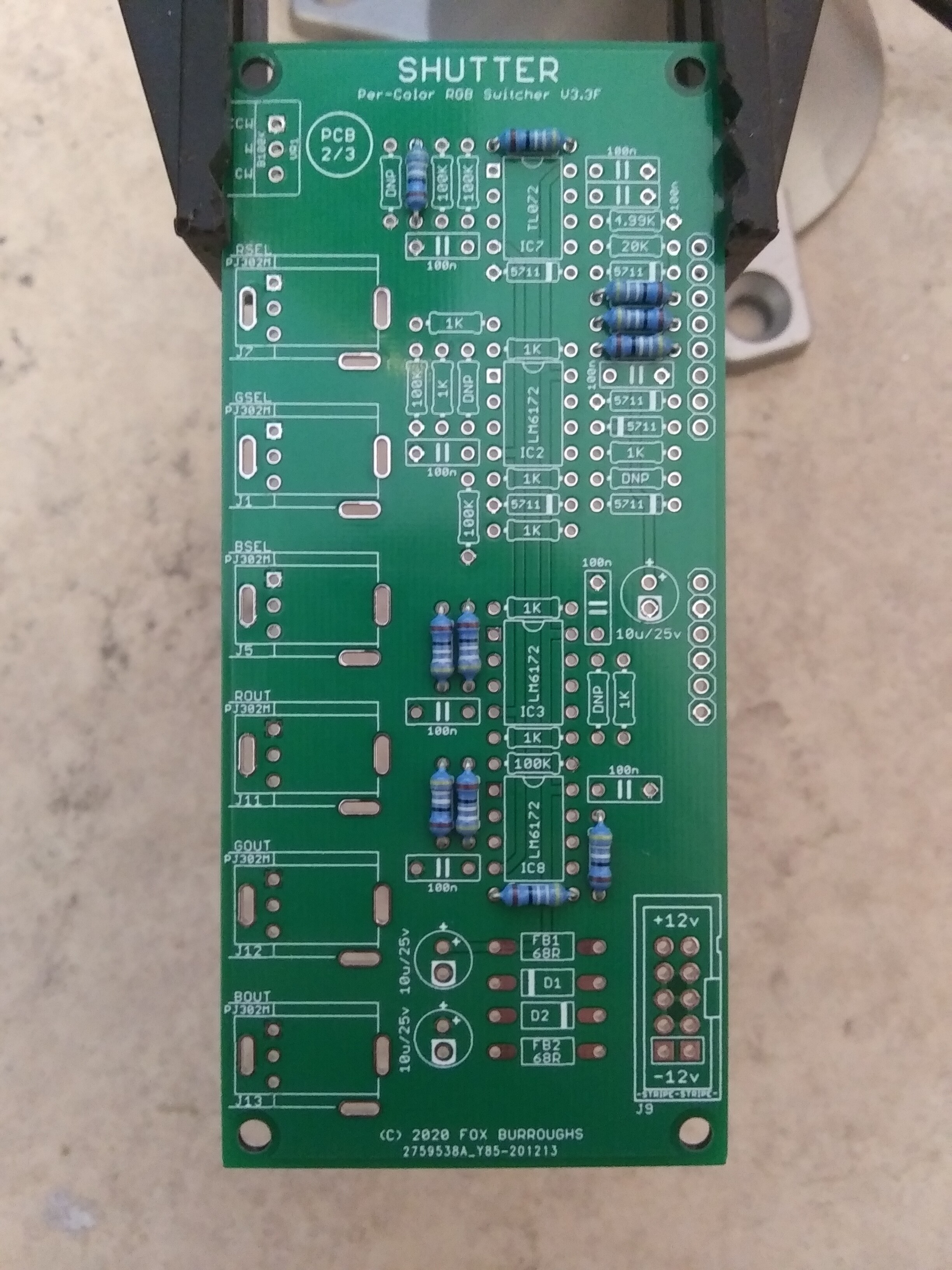
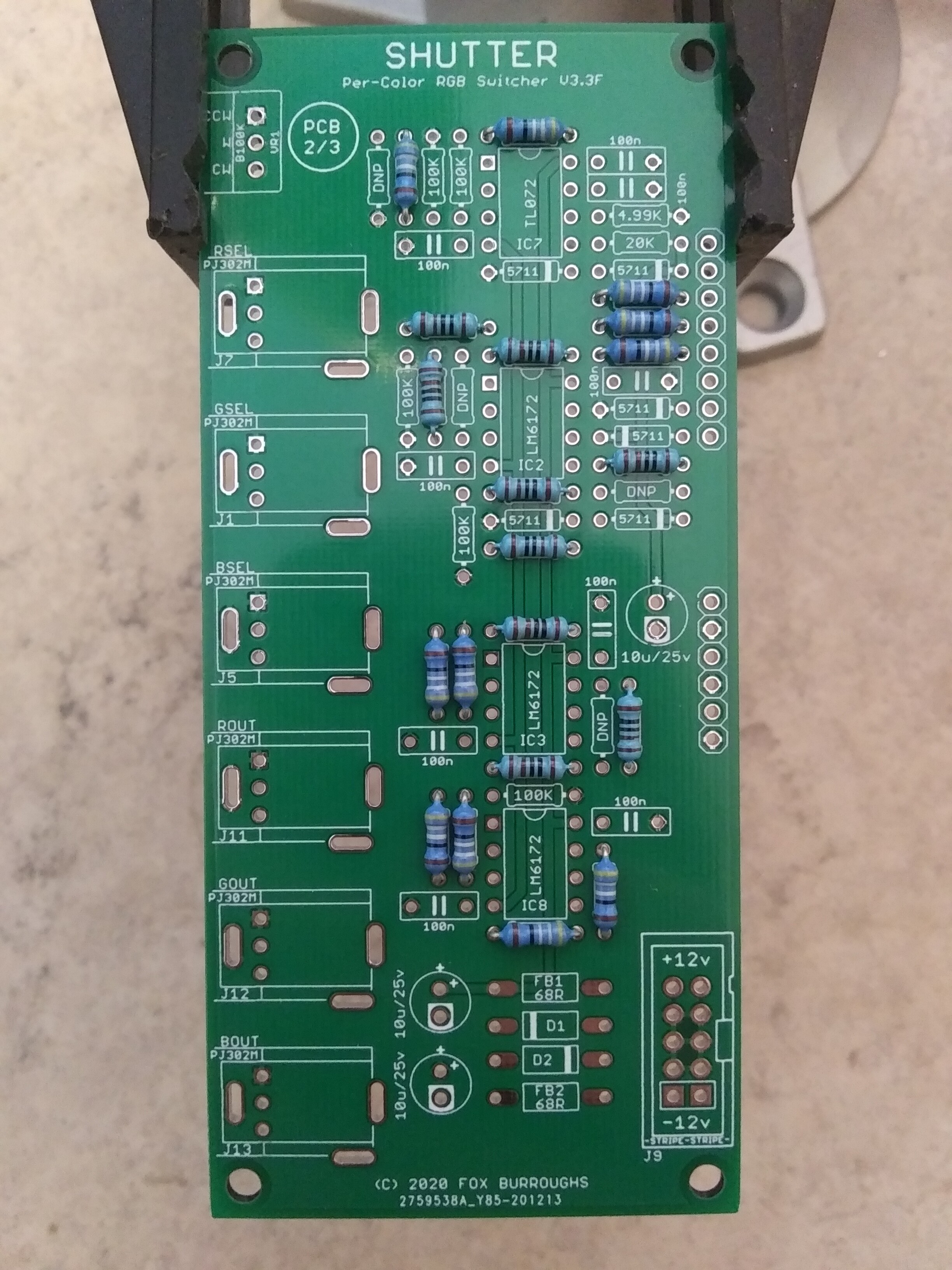
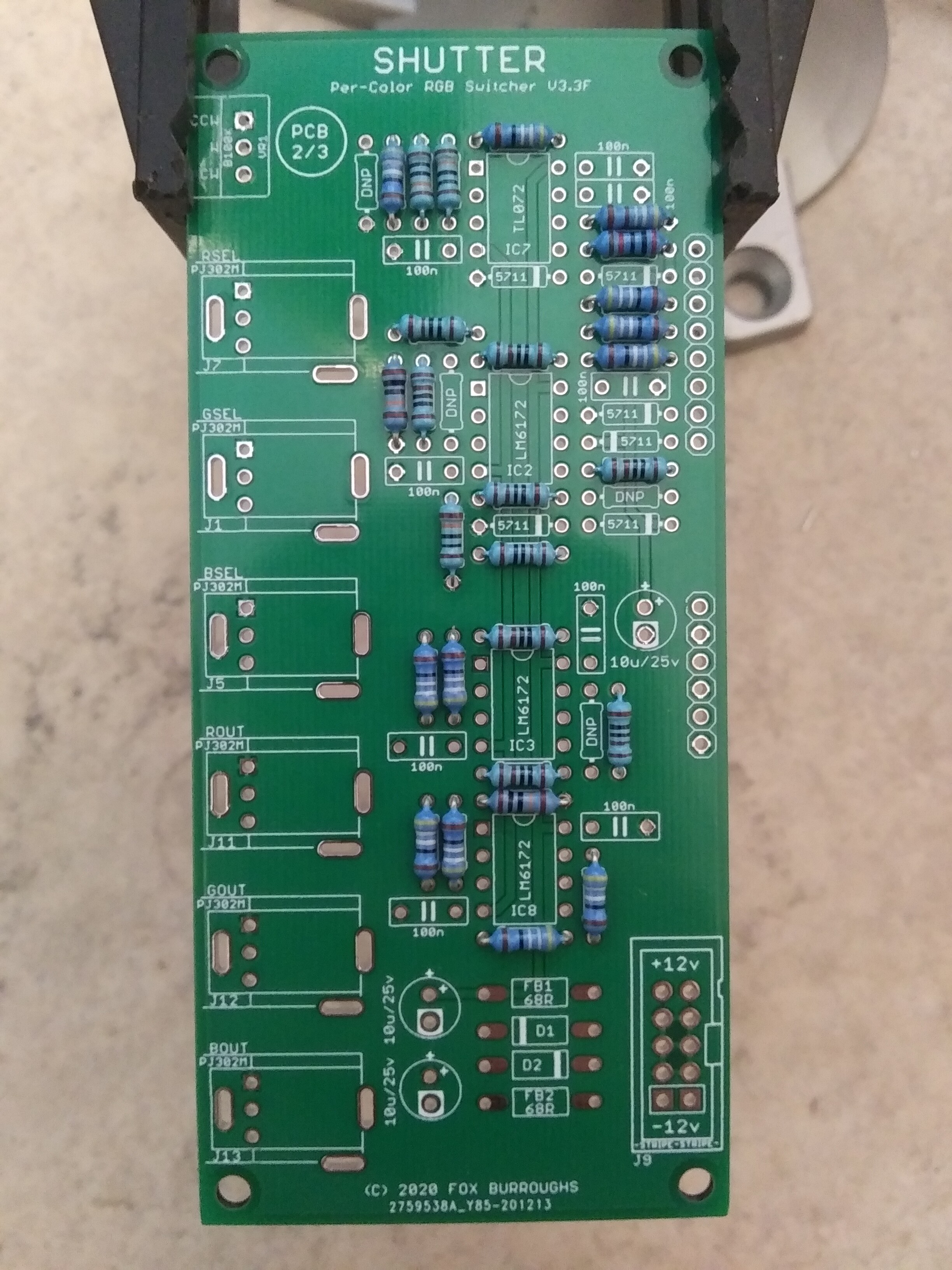
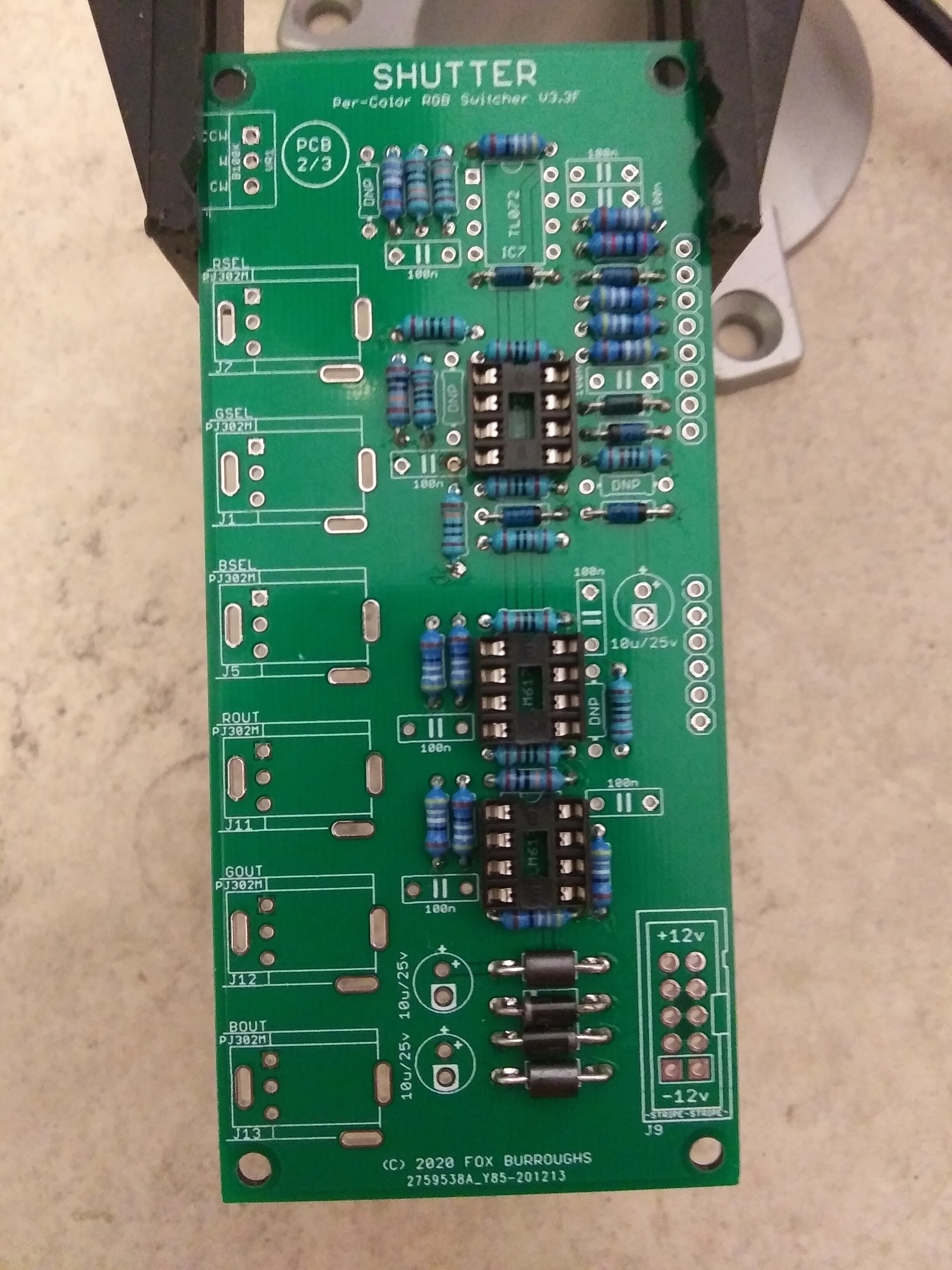
Expand for Build Guide Part 2Step 1:
Resistors.
Note, there are 6 resistors which we will not be populating. Board you receive will either show them blacked out or printed with DNP. Pictures will be updated shortly.

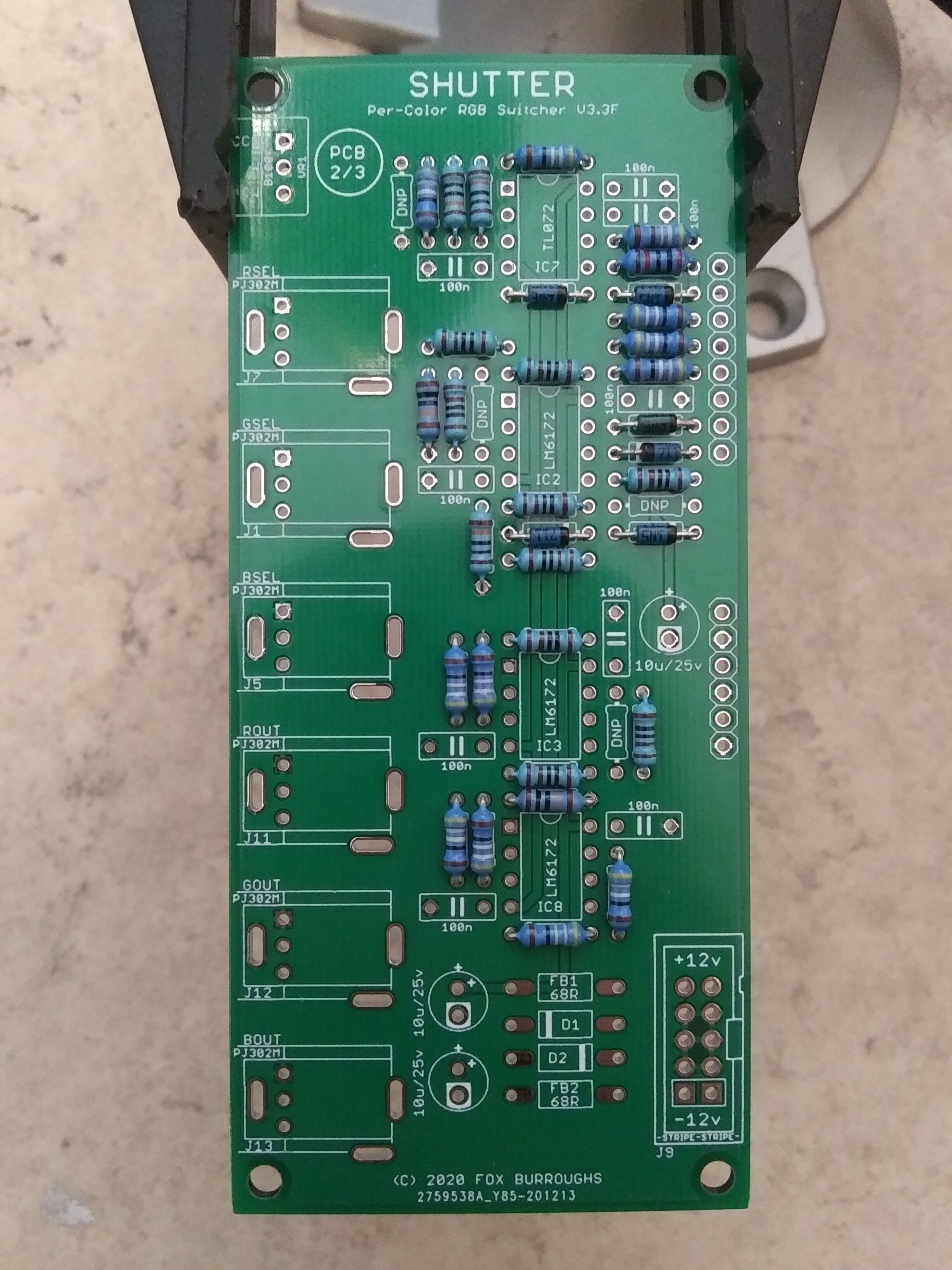
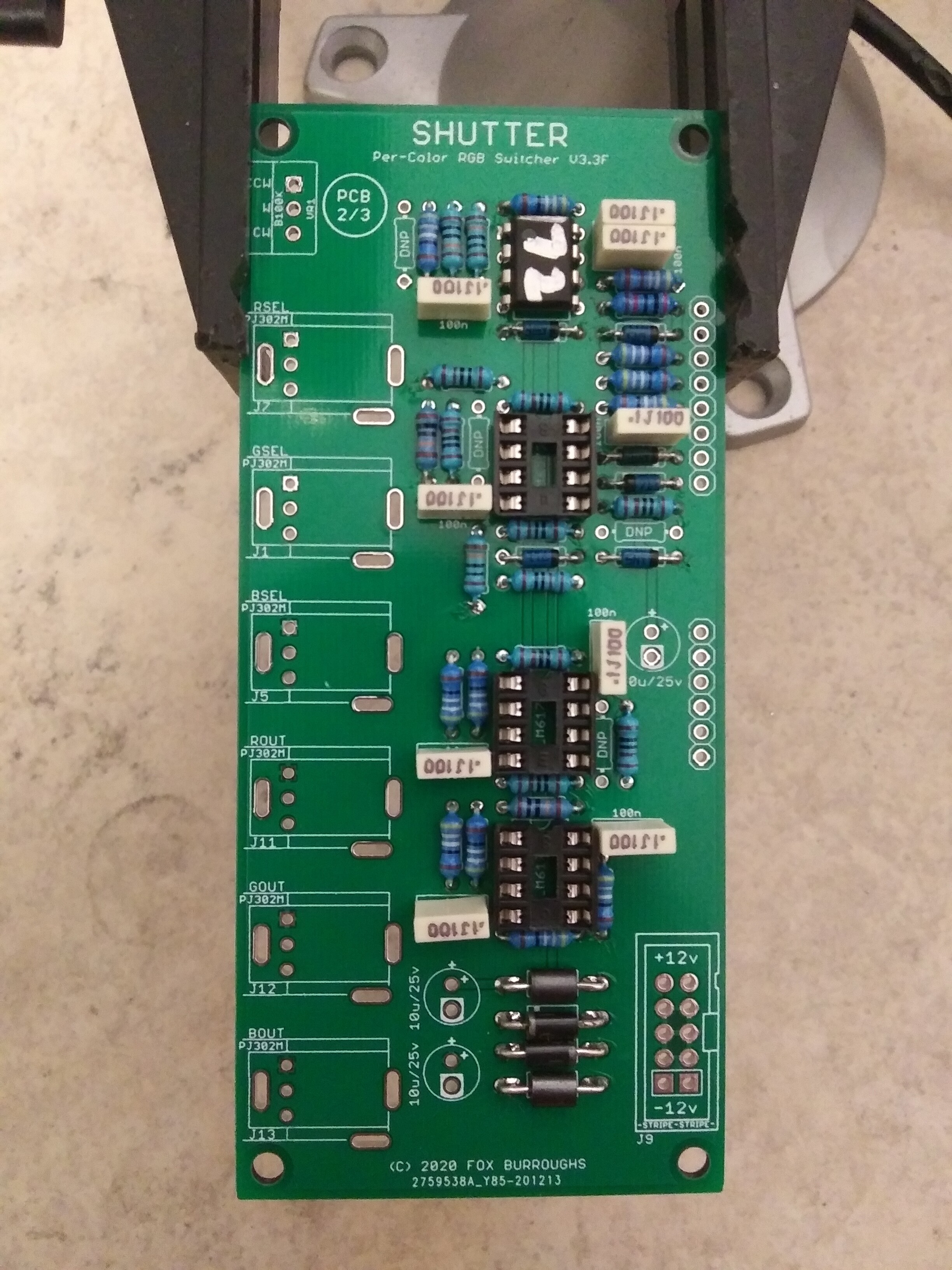
Step 2:
Decoupling capacitors
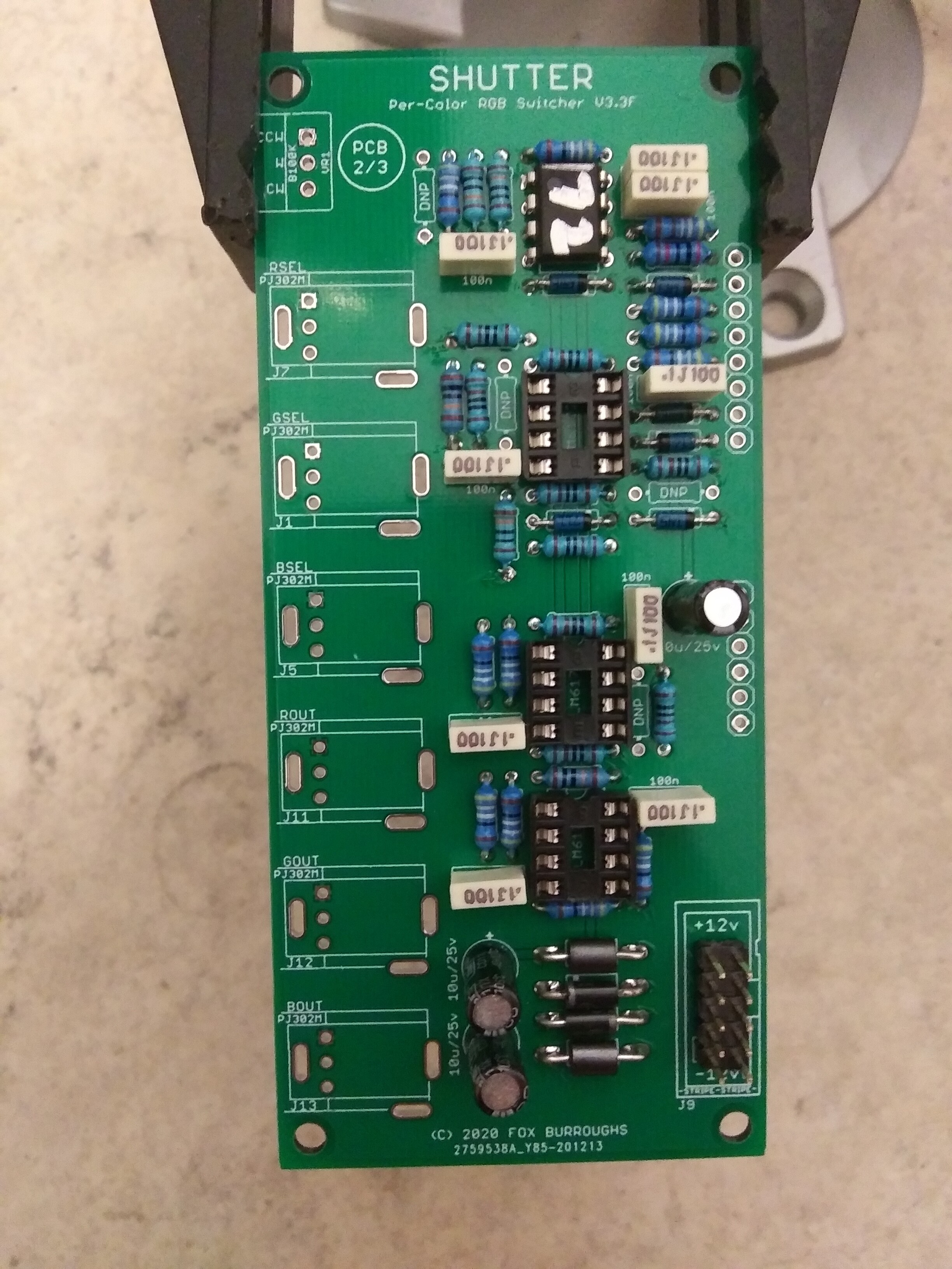
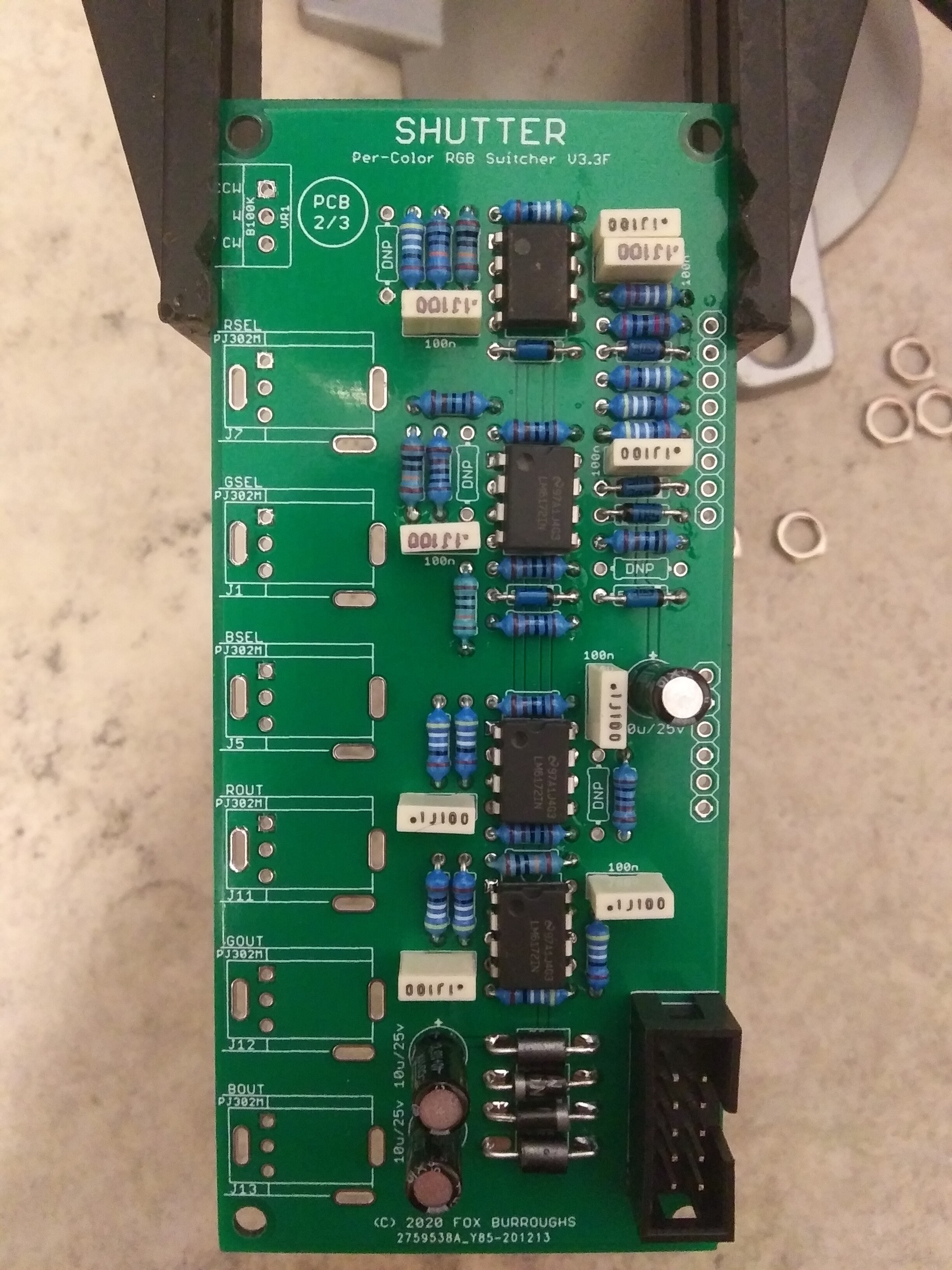
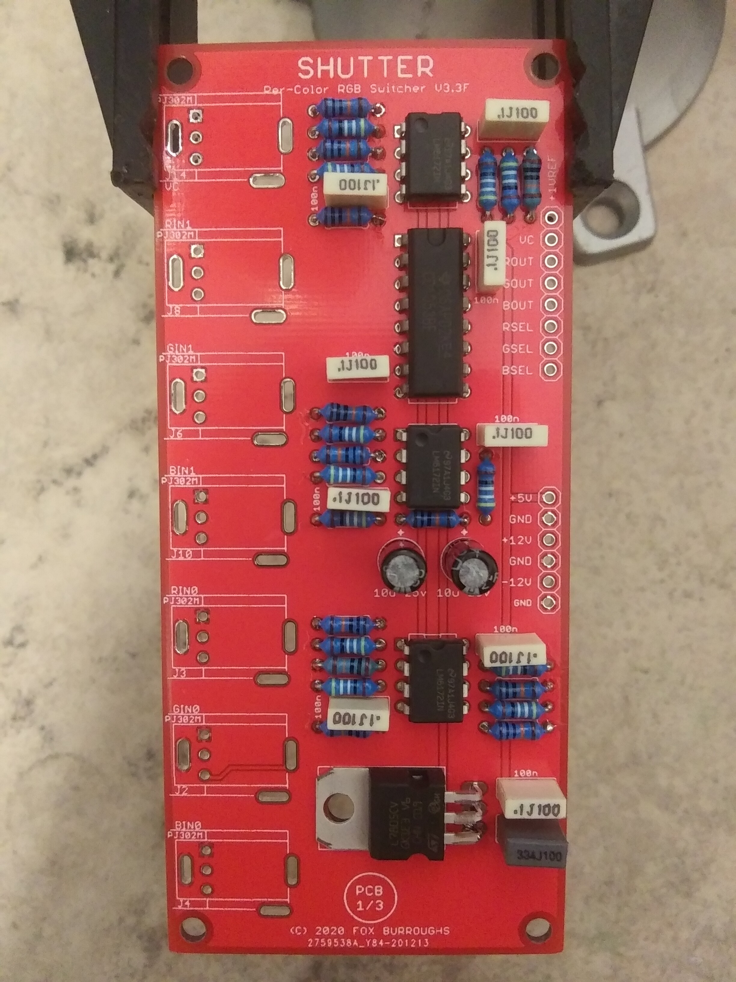
Step 3:
IC’s
Step 4:
As before, add the jacks to the board but do no solder them in place. place the jacks through the faceplate and finger tighten nuts on each jack. Once the jacks are straight, then solder them in place.
Step 5:
Without removing the faceplate from (PCB 2/3), add (PCB 1/3) back onto the faceplate. You may choose to tighten all nuts in place at this point.
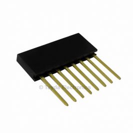
Locate your stackable headers and connect the single-row pin header to them. You will need one 6-pin stackable header and one 8-pin as well as 14-pins of normal header pins.
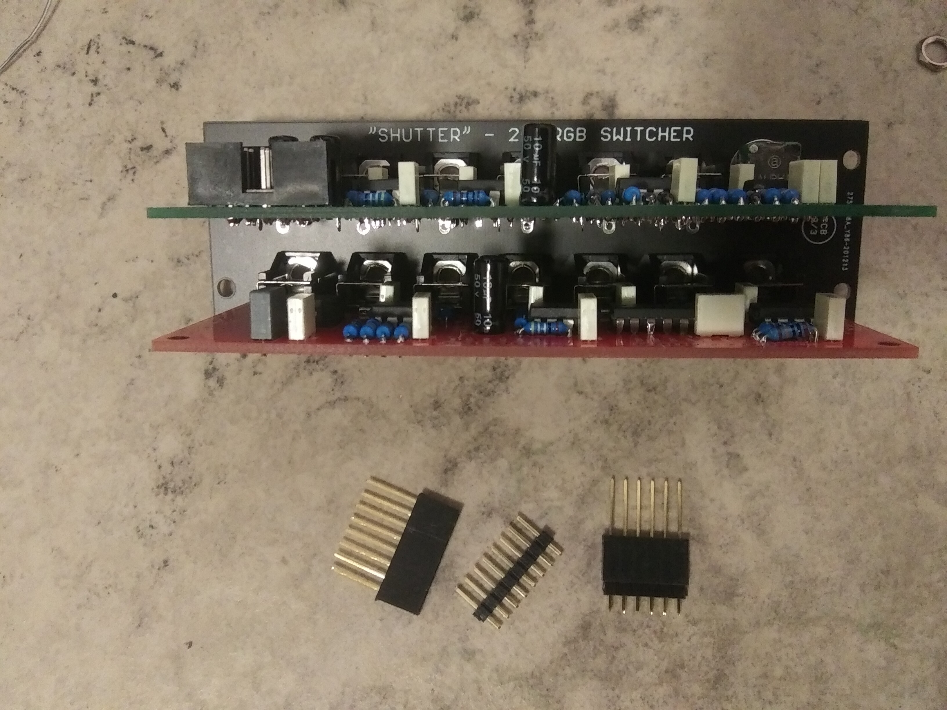
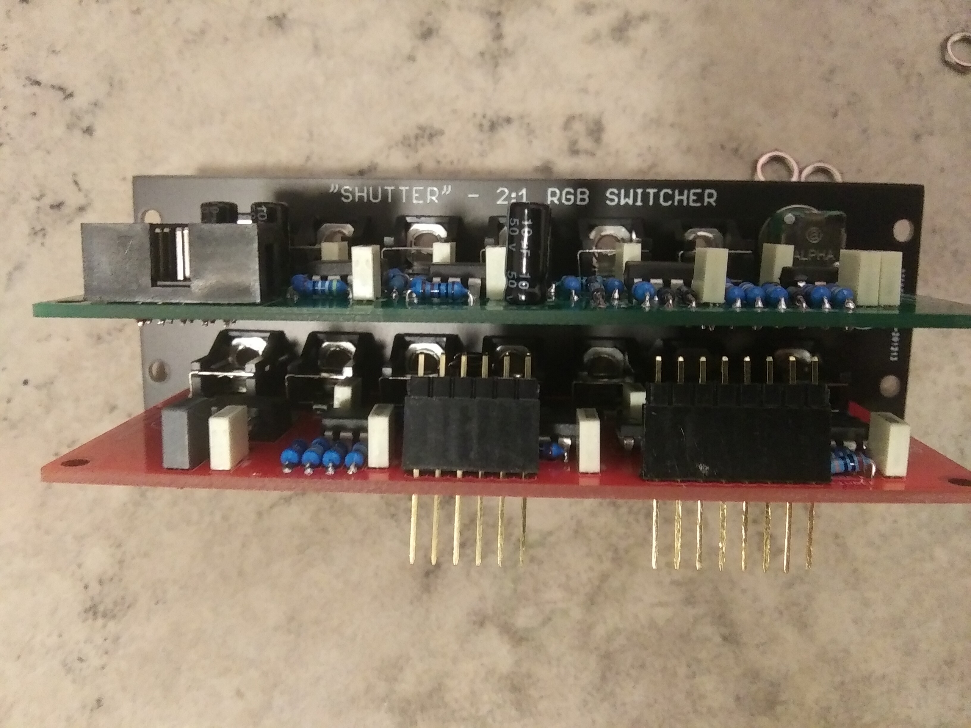
Insert the headers between boards and let them fall into place.
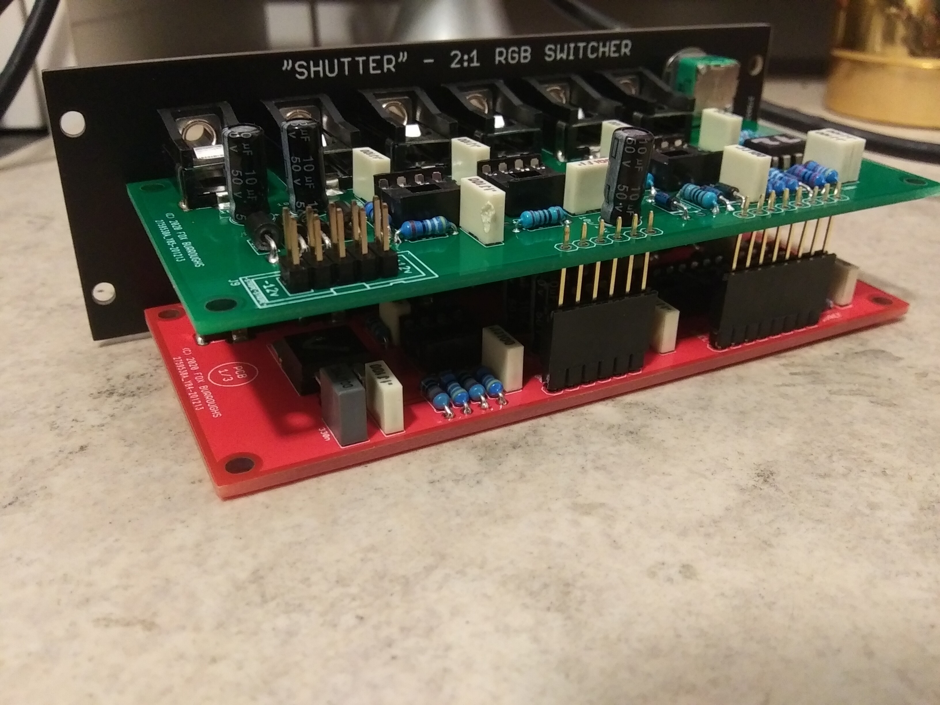
Turn the board back over and adjust the pin headers until they poke through both PCBs. Solder each pin in place.
Step 6:
Make sure all of your nuts are tightened and add the knob to the pot.
I center my knob, pointing vertically, but you may alternatively turn the pot completely Counter Clockwise and add the knob to point at the Letter “A”.
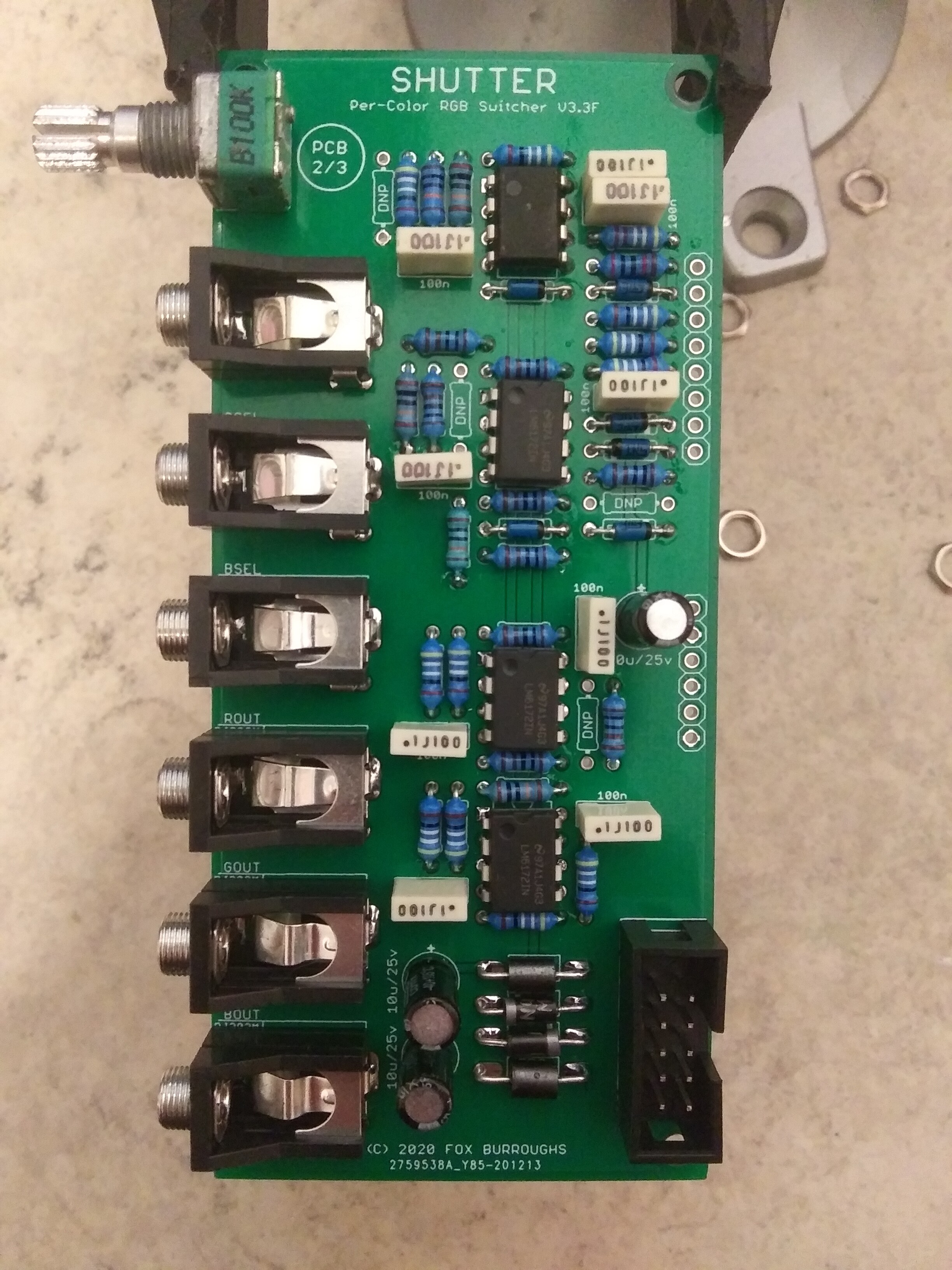
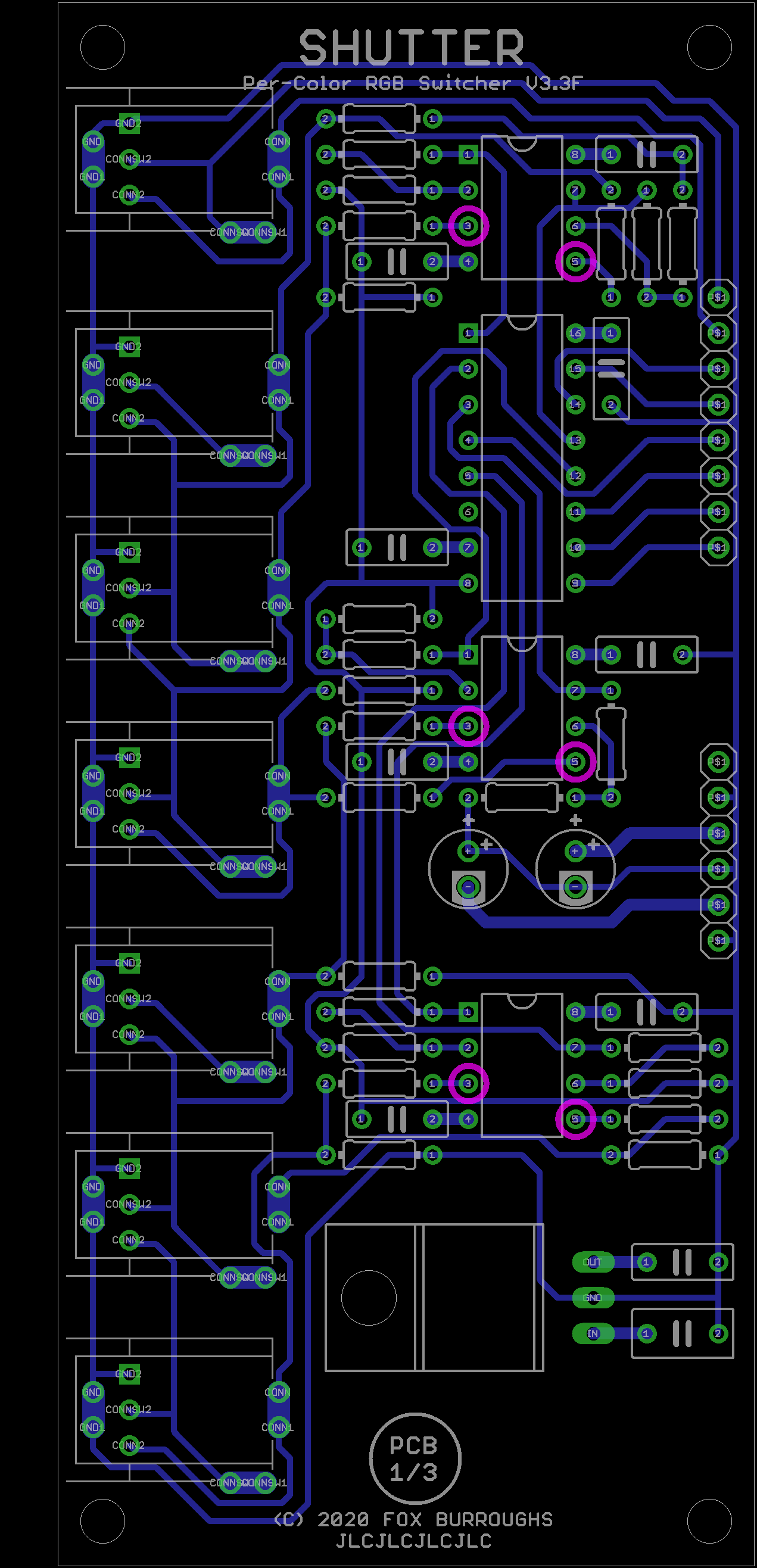
Optional ModificationsThis short guide illustrates the locations to add 1N5711diodes so that all inputs are +/-12V tolerant.
Voltages will be clipped at +5v. You will need an additional six 1N5711 diodes.
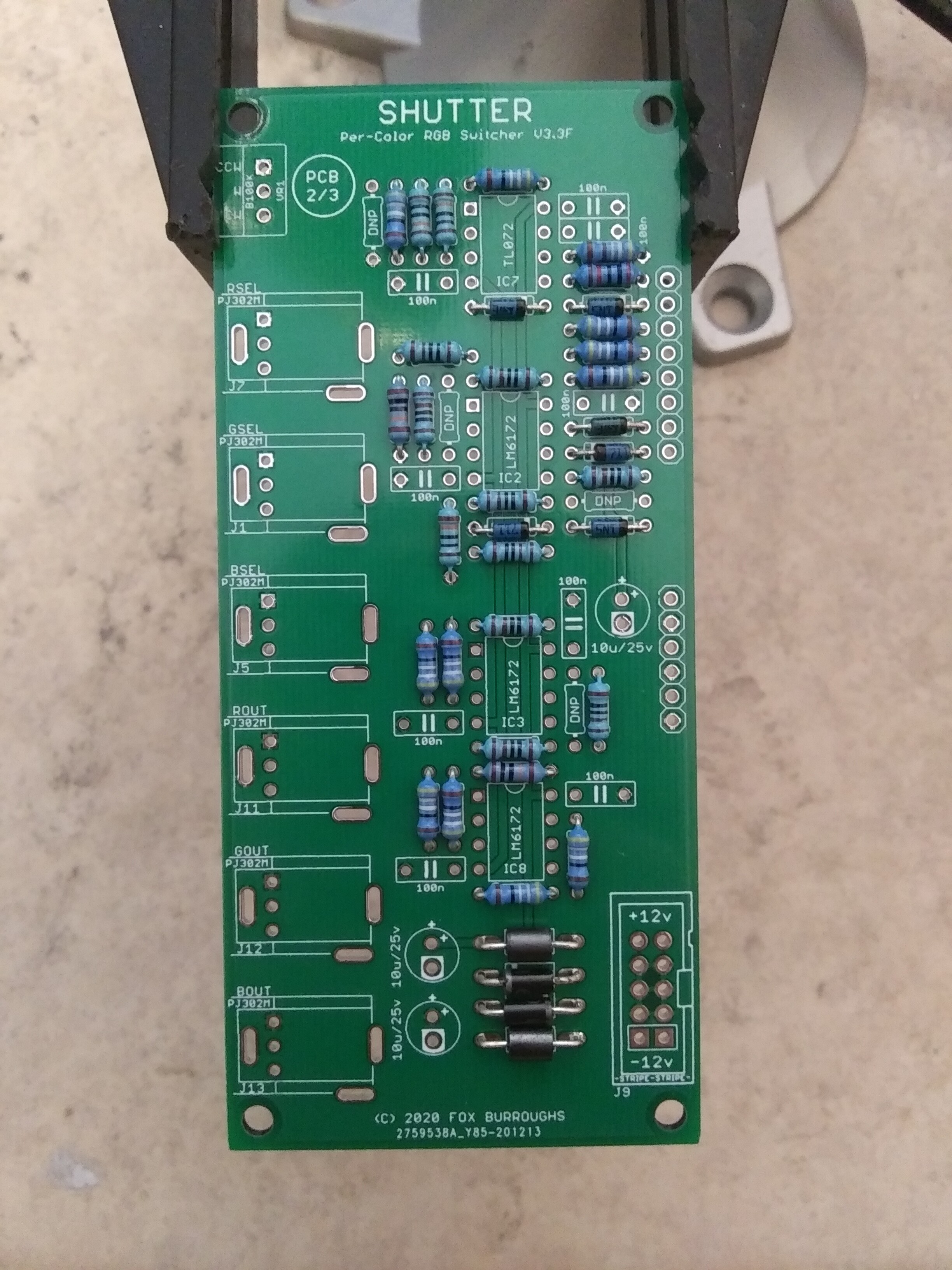
Pins 3 and 5 of each LM6172 will require a diode. The anode (non-stripe side) of each diode connects to these pins, circled in pink below:
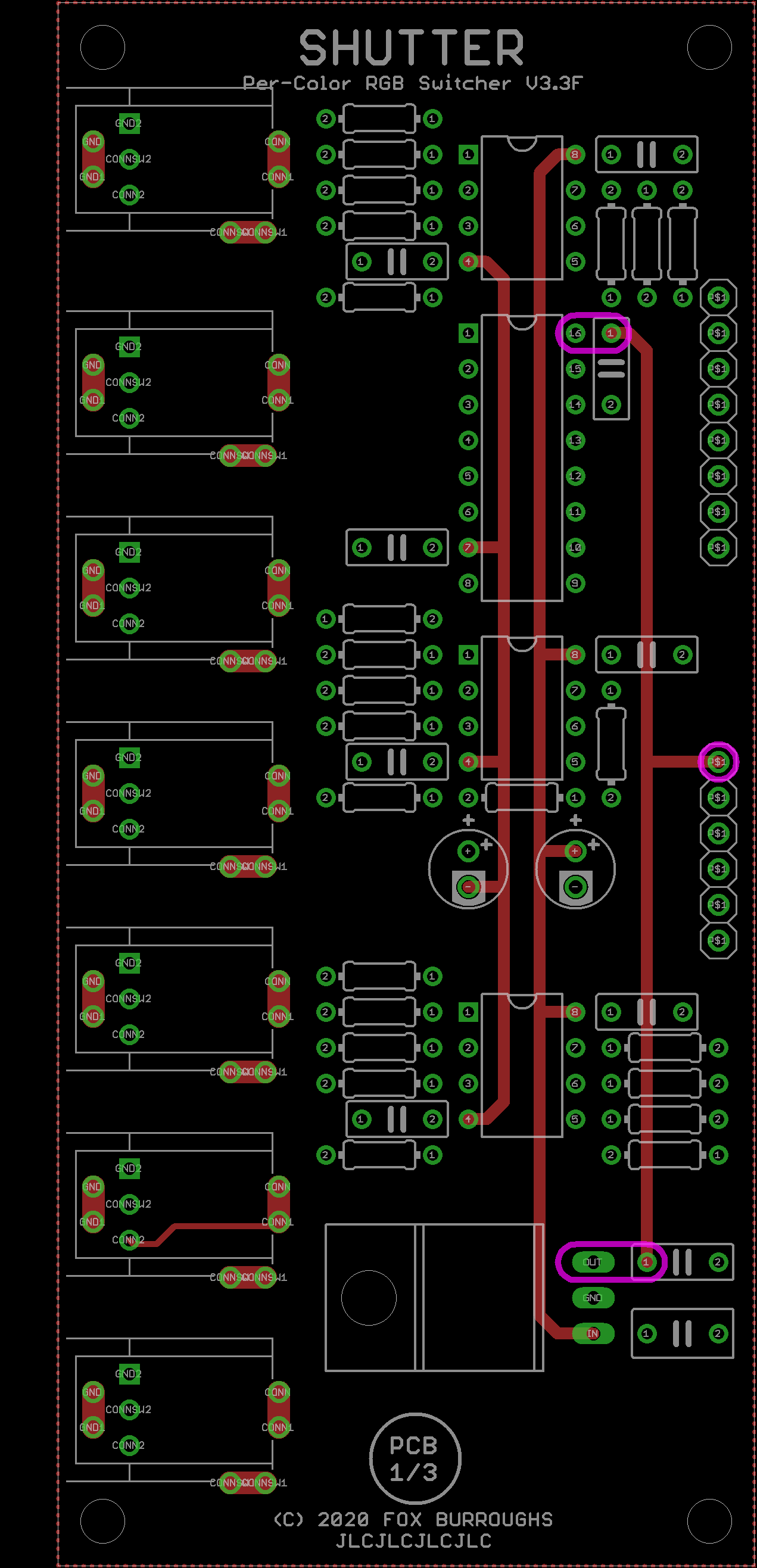
The Cathode of each diode will connect to a +5v source. Which ever +5v point that is closest will work.
Circled below in pink are all of the 5v locations.
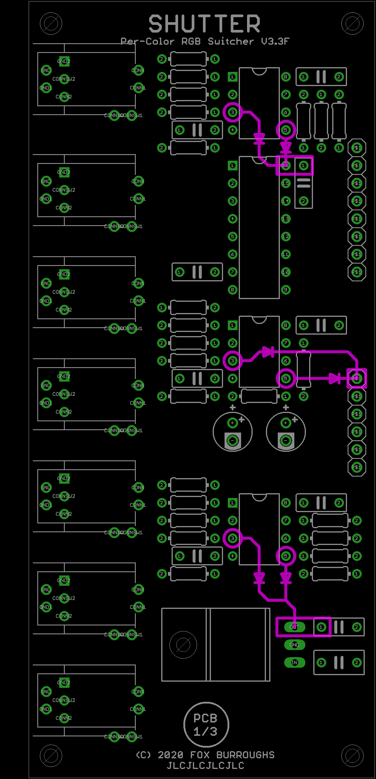
The third image shows a diode connected to the nearest 5v source. I will add a photo of the actual process shortly.
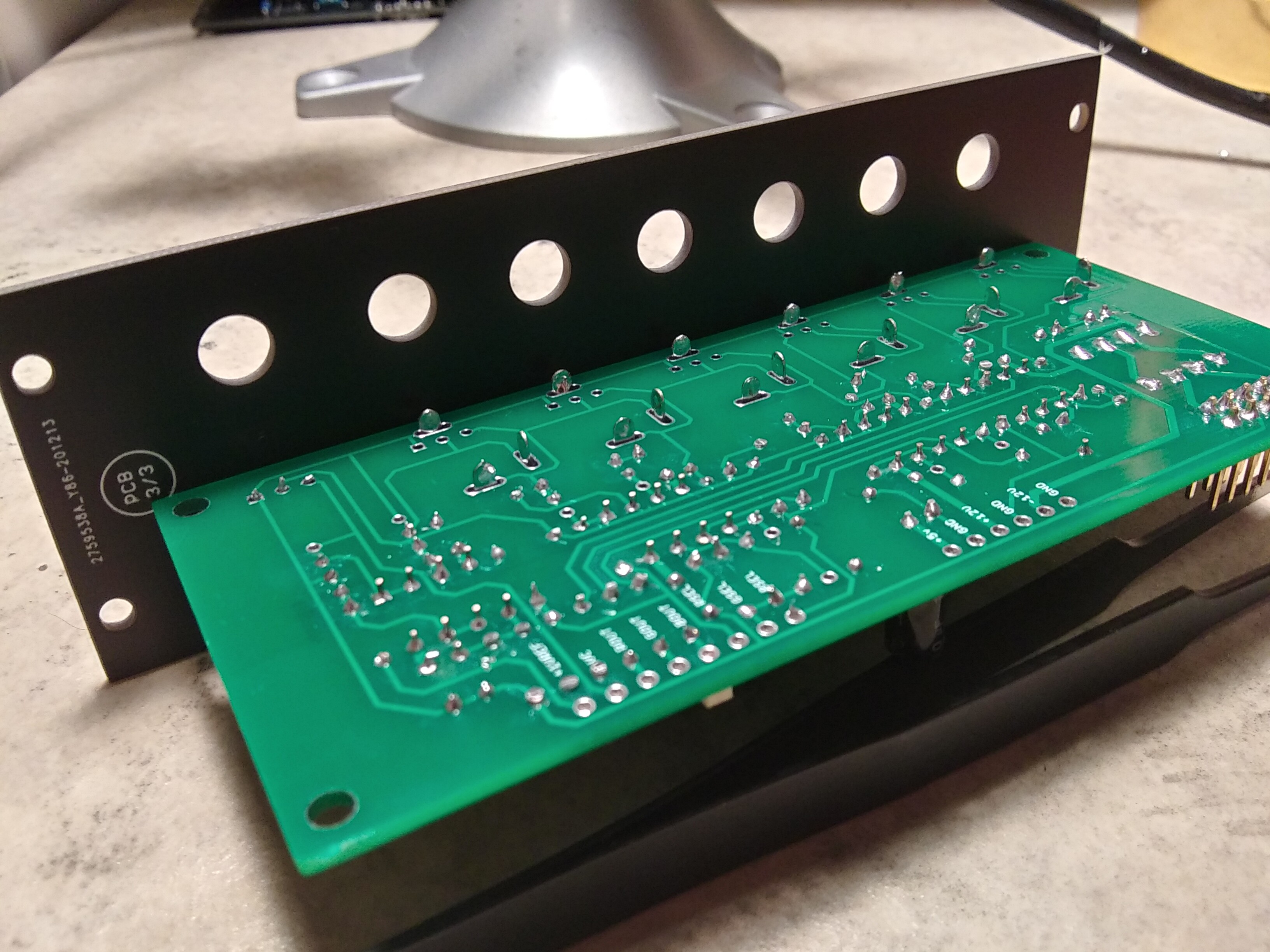
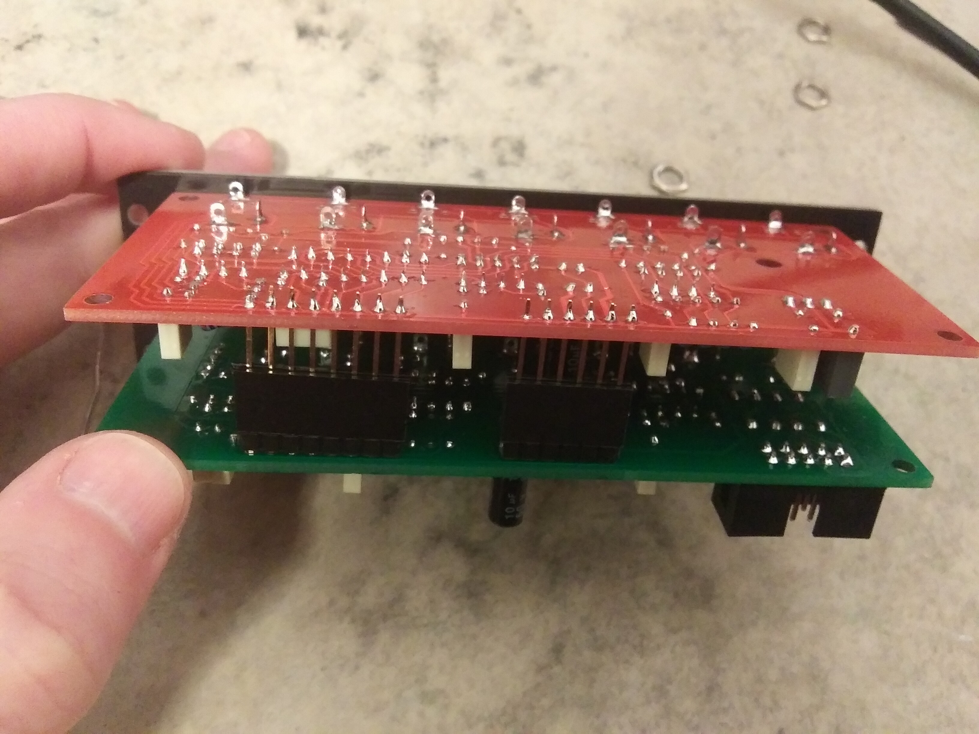
And finally, here is a photo of the diodes installed to the bottom of the PCB.
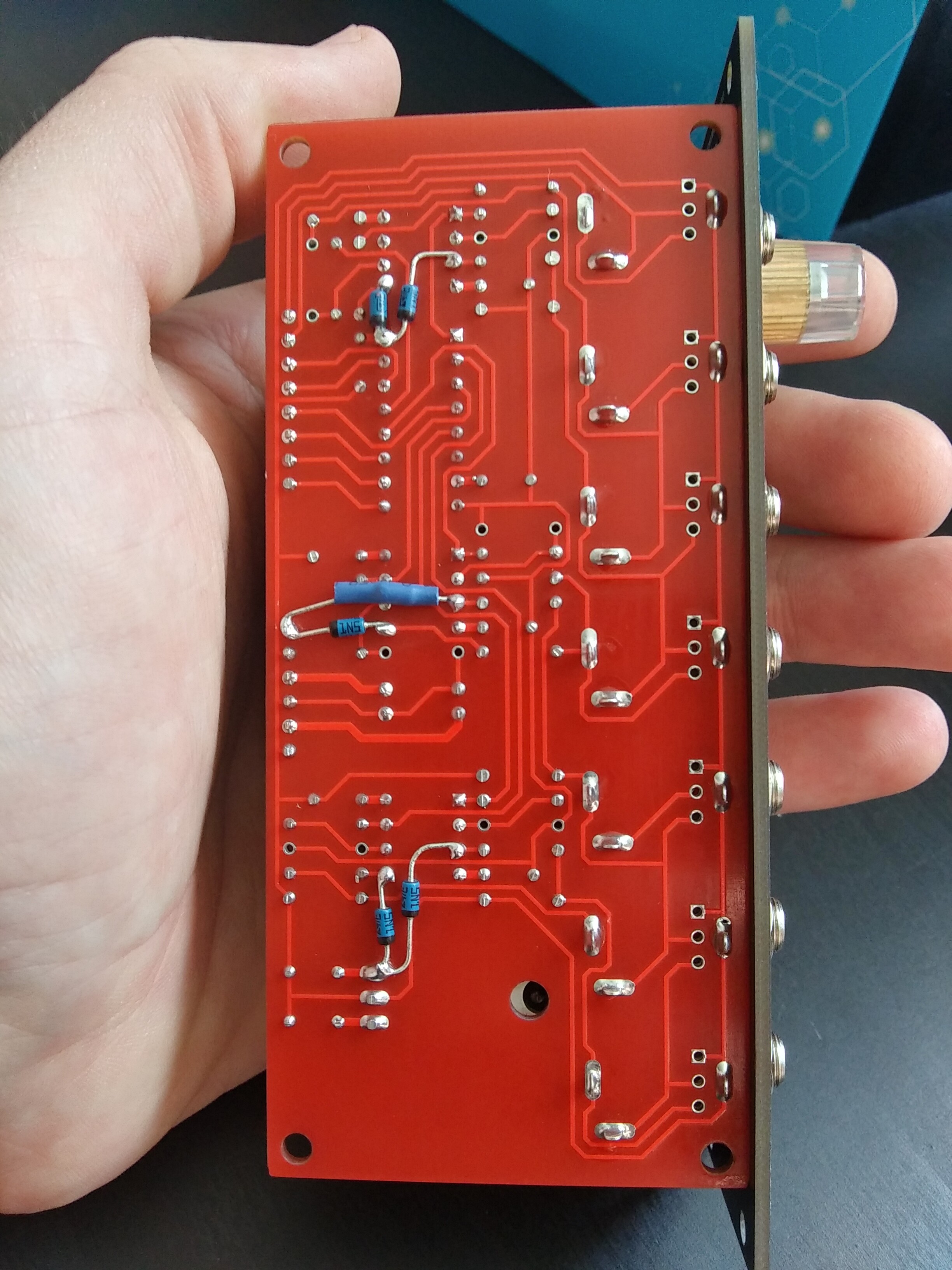
Again, all pre-built orders for Shutter will come with these diodes installed.
#4 — Fox · 2021-03-08
reserved for something else maybe.
#5 — Rik_bS · 2021-03-08
Are the PCB + Panels being built to order, or will you keep stock to purchase in a month or two?
A few of your planned modules look interesting, but having to pay for international freight I’d be reluctant to buy them one at a time
#6 — VanTa · 2021-03-08
Are you planning any European retailer? Raw Voltage Wien being the best option

#7 — TrashTeam · 2021-03-08
Interested in a built module.
#8 — Fox · 2021-03-08
Rik_bS wrote:
Are the PCB + Panels being built to order, or will you keep stock to purchase in a month or two?
A few of your planned modules look interesting, but having to pay for international freight I’d be reluctant to buy them one at a time
The first round will be built to order, but I will be working toward having more on hand.
I agree that international shipping is crap. Maybe I can find a retailer that would stock a few for me like VanTa mentioned.
VanTa wrote:
Are you planning any European retailer? Raw Voltage Wien being the best option
>>>
Do you think they may be interested? I’ll try contacting them, thanks!
TrashTeam wrote:
Interested in a built module.
Messaging.

#9 — Agawell · 2021-03-08
Raw Voltage (Austria) are selling LZX, Reverse Landfill and Syntonie Kits alongside built modules and those from afterlife laboratories and brownshoesonly
Exploding Shed (exploding-shed.com - Germany) may also be an option - no video modules yet, but they do seem to be expanding their range - so you never know! almost completely DIY
Thonk (thonk.co.uk - UK) - is also a good idea - especially given brexit - for all the UK residents - they also sell lzx, reverse landfill and syntonie video diy
I think that’s it for european dealers that sell video diy modules
There are a few that sell built modules, but most are ‘by request’ sales - ie we’ll order it for you
I’d also approach at least one dealer in the US - synthcube is the only 1 I know though
good luck!
I’ll probably end up with a full set (including some duplicates) of your modules when they are more easily available in europe, especially if pcb/panel sets are available
#10 — Agawell · 2021-03-08
error instruments (errorinstruments.com - Netherlands) might also be interested - they sell some diy if I remember correctly & Paul follows me on instagram…
#11 — Fox · 2021-03-08
Agawell wrote:
Raw Voltage (Austria) are selling LZX, Reverse Landfill and Syntonie Kits alongside built modules and those from afterlife laboratories and brownshoesonly
Exploding Shed (> exploding-shed.com> - Germany) may also be an option - no video modules yet, but they do seem to be expanding their range - so you never know! almost completely DIY
Thonk (> thonk.co.uk> - UK) - is also a good idea - especially given brexit - for all the UK residents - they also sell lzx, reverse landfill and syntonie video diy
I think that’s it for european dealers that sell video diy modules
There are a few that sell built modules, but most are ‘by request’ sales - ie we’ll order it for you
I’d also approach at least one dealer in the US - synthcube is the only 1 I know though
good luck!
I’ll probably end up with a full set (including some duplicates) of your modules when they are more easily available in europe, especially if pcb/panel sets are available
Agawell wrote:
error instruments (> errorinstruments.com> - Netherlands) might also be interested - they sell some diy if I remember correctly & Paul follows me on instagram…
Thanks a bunch for those tips. I will try to reach out to them.
I can’t help feeling intrusive, but I suppose it has to be done.
#12 — jsonpayload · 2021-03-09
Please mark me down for 1 preassembled module!
I do have some questions in addition:
Fox wrote:
Multiple SHUTTER modules may be daisy-chained to switch between more than 2-RGB sets.
How exactly does this work? Is there a header to connect on the rear? If i buy preassembled modules, will I need anything else to connect them?
Separately, is there anything normalling built-in? Will the first “switch” input be normalled to the other 2? What about for the Ch. A or B inputs?
#13 — rempesm · 2021-03-09
jsonpayload wrote:
How exactly does this work? Is there a header to connect on the rear? If i buy preassembled modules, will I need anything else to connect them?
To switch between 3 RGB images, you would need to use 2 Shutters. Let’s say you have RGB images A, B, and C. Images A and B go into Shutter #1’s Ch. A and Ch. B inputs. Image C goes into Ch. A of Shutter #2 and the RGB output of Shutter #1 goes into Ch. B of Shutter #2. Just extrapolate from there for more inputs.
No rear connections are needed apart from power, it’s all achieved with front panel patching.
jsonpayload wrote:
Separately, is there anything normalling built-in? Will the first “switch” input be normalled to the other 2? What about for the Ch. A or B inputs?
Yes, there is quite a bit of normalling going on in Shutter to make patching easier!
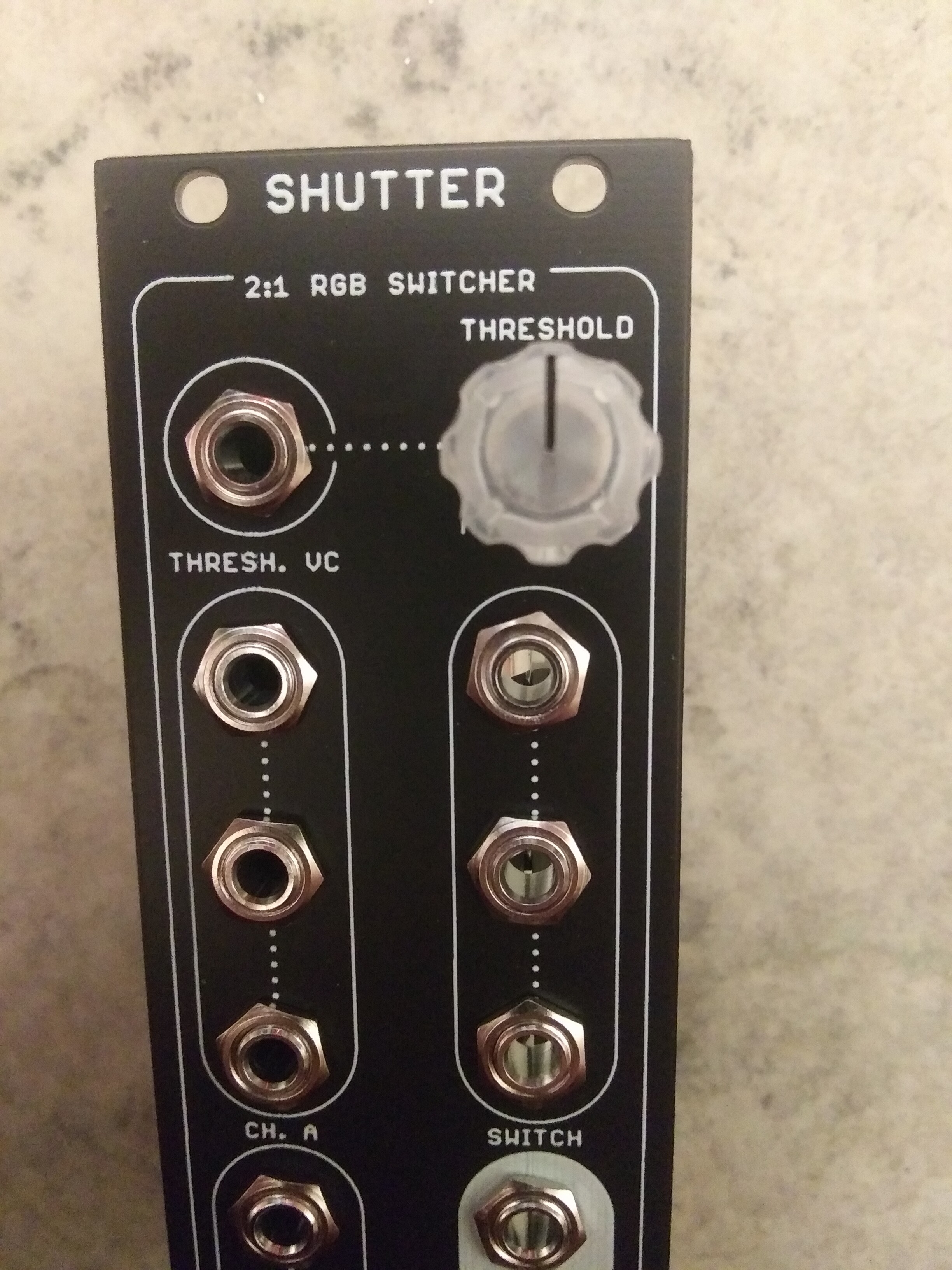
Ch. A’s inputs are normalled top>middle>bottom (or R>G>B). Same for Ch. B. Same for the Switch inputs but R is normalled to a 0.5V reference. The Thresh. VC input is normalled to a 1V reference which the Threshold pot attenuates. This is why you can switch between two sources with nothing patched into the Switch inputs or Thresh. VC–just wiggle the pot around 12 o’clock.
I’m sure @Fox will correct me if I goofed on anything here.
#14 — everyoneismyfriend · 2021-03-09
Put me down for 2 PCB/Panels please.
#15 — Fox · 2021-03-09
rempesm wrote:
I’m sure > @Fox> will correct me if I goofed on anything here.
Totally right. I’ll just reiterate since I was already typing.

jsonpayload wrote:
How exactly does this work? Is there a header to connect on the rear? If i buy preassembled modules, will I need anything else to connect them?
Great questions!
Daisy chaining modules is simply done via the front with patch cables.
First connect two RGB-luma-sets to Channel A and B on the first Shutter. Then connect the outputs of the first Shutter to Channel A of the second Shutter and a third RGB-Luma-set to Channel B of the second Shutter.
jsonpayload wrote:
Separately, is there anything normalling built-in? Will the first “switch” input be normalled to the other 2? What about for the Ch. A or B inputs?
Yep! The faceplate shows a dotted line to illustrate the normal switched connections.
RGB Channels A, B and the switching inputs are cascaded R>G>B.
I will suggest for switching monochrome images, that you use just a single MUX. For Example: The first input of Channel A, Channel B and first Switch input. Using all three switching circuits for a single monochrome image wastes the second and third switching circuits since you can use either a cable splitter or mult to get a monochrome image into your mixer or encoder.
I will be detailing best-practice patch examples below the original post soon.
everyoneismyfriend wrote:
Put me down for 2 PCB/Panels please.
Welcome to the forums, Brian! I certainly will. I’ll PM you as soon as I get back from the grocery store.
#16 — jsonpayload · 2021-03-09
I appreciate the dotted line hinting, didn’t realize that was what I meant on the YRGB distro module. Nice!!
#17 — mrfang · 2021-03-09
I need two PCB sets!
#18 — Makaiya · 2021-03-09
2 pcb’s for me please!
#19 — dr_how · 2021-03-09
I’d like to order one PCB set please!
#20 — RoseColouredGlasses · 2021-03-10
I’ll take 2x pcb/pannel sets
#21 — Jesse · 2021-03-10
I’d like to order 2 PCB sets
Lovely looking piece of kit, gonna be super handy

#22 — voidevaqion · 2021-03-11
looks great. up for a PCB set, thanks.
#23 — RawVoltage · 2021-03-12
Don‘t be shy - always welcome and yes, i am interested

Erwin from RawVoltage
#24 — Fox · 2021-03-12
Oh wow, Hi Erwin! I’ll contact you soon.
#25 — everyoneismyfriend · 2021-03-13
Got mine today!
#26 — Fox · 2021-03-13
Love to see it!
And as for the Built Modules, parts are ordered. I only have a few more PCB/panel sets from this batch so if anyone needs a PCB/Panel set or Built Module, holler.
#27 — video.pls · 2021-03-13
I’ll take a built module!
#28 — droningbrightnessav · 2021-03-13
Hey @Fox I would like to buy a pcb/panel set! <3
#29 — Fox · 2021-03-13
Thats a wrap. I have to cut off orders now and I’ll order more soon.
In the meantime, many PCB/panels sets are showing at their final destinations and parts to build 15 of them are en route to me.
I will be in contact as I build, test and ship the remaining orders.
#30 — everyoneismyfriend · 2021-03-15
Is there a recommended Mouser part for the 100nF and 330nF capacitors? I’ve never sourced this style and don’t wanna end up with something weird.
#31 — Fox · 2021-03-15
everyoneismyfriend wrote:
Is there a recommended Mouser part for the 100nF and 330nF capacitors? I’ve never sourced this style and don’t wanna end up with something weird.
Do you mean the box-looking caps? They’re nothing special. I typically get that style because they’re cheap and sit nice and flat. Just get some MLCC’s like these: https://www.mouser.com/ProductDetail/791-RD21B104K500A5HA https://www.mouser.com/ProductDetail/810-FG28X7R1H334KRT6
#32 — Fox · 2021-03-19
Nearly all of the parts have arrived for the built modules.
#33 — Jesse · 2021-03-20
Anyone have a mouser cart to share for the BOM?
#36 — Jesse · 2021-03-20
@DesertMuseum Must have missed it, thx

#37 — Jesse · 2021-03-20
@DesertMuseum Wait, I see the BOM but no mouser cart - am I blind? I’ve scrolled the thread 3 times now
#38 — Fallinggirl · 2021-03-20
Paul from Error Instruments is my boyfriend. I’ll ask him for you if you want. He is very interested in video synthesis now. Paul is presently distributing Gieskes but wanting to expand.
And, I want to purchase a prebuilt Shutter. Please let me know when they are ready. Your designs are brilliant.
#40 — video.pls · 2021-03-22
I appreciate you keeping us updated. Can’t wait

#41 — Whelm · 2021-03-23
Dang, missed this. Would be interested in PCB set if you do another run. Need to pay more attention to this forum.
#42 — Fox · 2021-03-23
Don’t worry about it, I will have more coming soon.
#43 — Fox · 2021-03-23
Parts are all here, going to start soldering tonight.
I sure have my work cut out for me.

#44 — Maytoast · 2021-03-24
You got this! Slow and steady.
#45 — mattzog · 2021-03-24
I feel like a lazy DIYer because I’m waiting for someone else to post a Mouser cart. I’ve been busy with work stuff and haven’t spent the time to make my own. BAD SYNTHESIST, BAD!
If I get to it first, I’ll post it for any other reprobates.
Cheers y’all, and thanks Fox!
#46 — Marizu · 2021-03-25
I feel your pain.
Sometimes it’s difficult to share a Mouser cart. My next order will be for 7 modules. There will be a lot of cart optimisation (buying extras to hit price breaks) that will only make sense if you are building the same stuff as me. I also already have some of the components, so they won’t be in the cart.
#47 — Marizu · 2021-03-25
I just noticed that it says:
- CH A. & CH. B inputs: +5v/-12v tolerant
Does that mean that it can be damaged if more than +5V goes in to an input?
My system is a mixed audio and video system. I often send outputs from things like Maths directly in to it. Is this likely to be a problem?
#48 — VisibleSignals · 2021-03-25
CD4053 has limited max supply voltage (20V p-p I think) so probably being run off -12V and +5V rails (via 7805). > Vcc will eventually hurt the CD4053. Quick and easy fix would be a diode to +5 to drain away higher voltages excursions though.
#49 — saiteron · 2021-03-25
Fox wrote:
The first round will be built to order, but I will be working toward having more on hand.>>>> I agree that international shipping is crap. Maybe I can find a retailer that would stock a few for me like VanTa mentioned.
happy to build a few of everything to keep on hand and i don’t mind shipping internationally. will be in touch soon about an order

#50 — Fox · 2021-03-25
Marizu wrote:
I just noticed that it says:
-
CH A. & CH. B inputs: +5v/-12v tolerant>>>>> Does that mean that it can be damaged if more than +5V goes in to an input?>>>> My system is a mixed audio and video system. I often send outputs from things like Maths directly in to it. Is this likely to be a problem?
Yes, sending signals beyond those limits is outside of the CD4053’s absolute maximium ratings. The other inputs are protected, but the idea of the modules is just to switch luma signals. A Cadet V or similar scaler would be rerecommended for your system.
I’ll add an addition to the build guide for DIY’ers who want to modify their modules.
#51 — Fox · 2021-03-26
I have more diodes on the way, so the pre-built modules will be modified for full rail-to-rail protection on all inputs.
#53 — mattzog · 2021-03-26
I read above and my question was already answered.
#54 — reverselandfill · 2021-03-27
the pcb set just came in !

#55 — everyoneismyfriend · 2021-03-29
Just waiting on my back ordered CD4053 chips to come in!
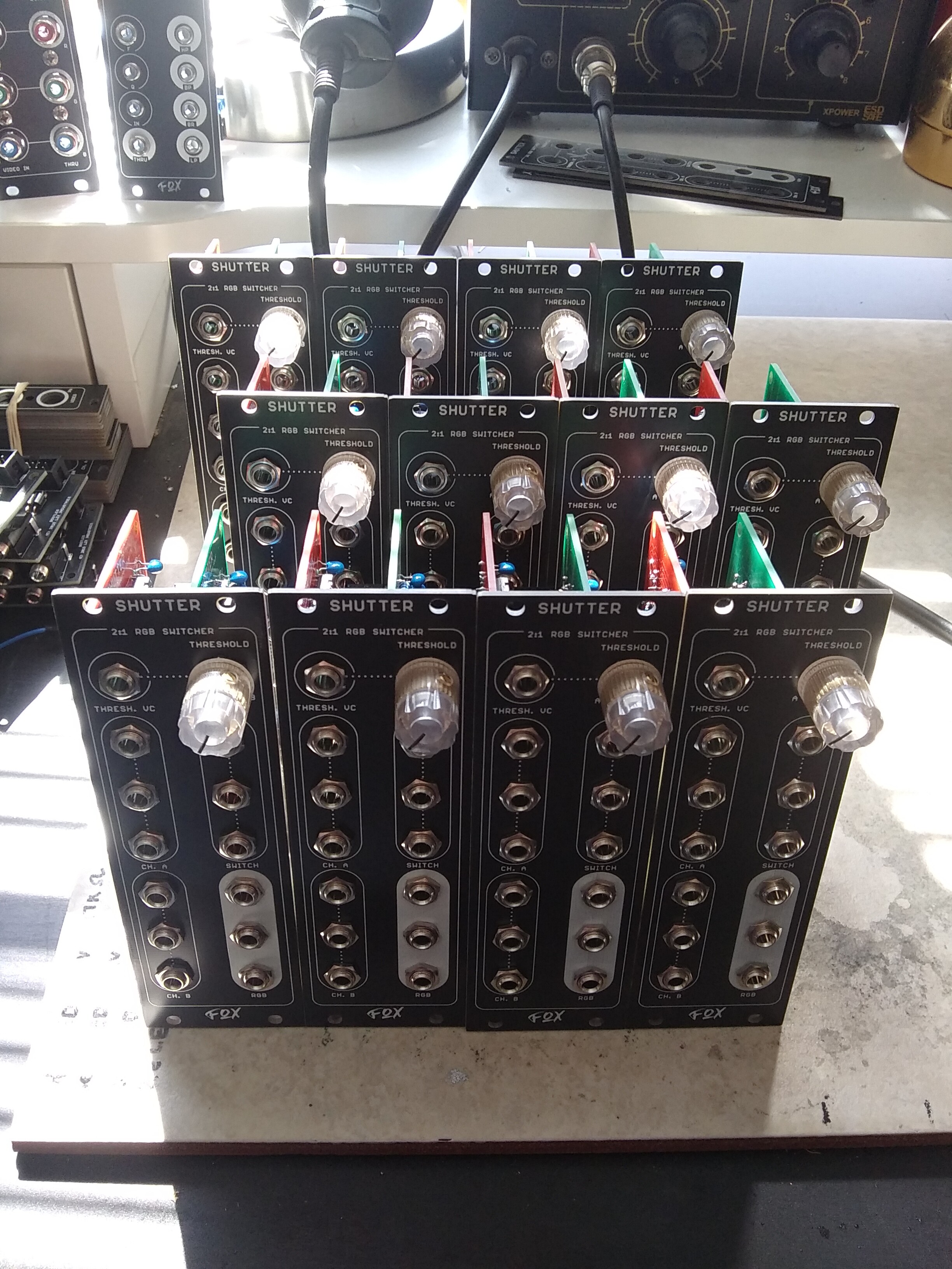
#56 — Fox · 2021-04-05
All modules built and extra diodes installed. Modules will be tested and shipped very soon.
I also did my best to add it to ModularGrid: Other/unknown SHUTTER - Eurorack Module on ModularGrid
#57 — IronEgg · 2021-04-08
If more orders open up, I’d be thrilled to order a built module. DIY could also work if that’s all that would be available. This looks so fantastic! Thanks for creating it!
#58 — video.pls · 2021-04-09
These look beautiful

#59 — phosphenes · 2021-04-09
Modules look amazing, looking forward to the next run of PCBs to build myself one!
#60 — Fox · 2021-04-11
All built modules will be shipping tomorrow morning.
More PCBs are also on the way for anyone who messaged me too late.
#61 — Robbertunist · 2021-04-12
Hey @Mattzog & for everyone else as well, this is my own BOM, it should be fine. If you import it into Mouser, I’m sure the Stackable Headers will cause issues because I hardwired the URLs to Tayda in there, maybe take them out and save a 2nd copy, use that with the Mouser BOM tool.
For feck sake, I can’t upload a non image file

OK, after about an hour of fucking about, this should be it. https://www.mouser.de/ProjectManager/ProjectDetail.aspx?AccessID=c83f08b2c0
I couldn’t add the regular 40pin 1row header so here’s the Mouser Product Nr.: 571-4-103327-9
I compared the lenghts to headers I’ve hear and it seems correct but don’t hold me to it.
Also the tall (arduino style) stackable headers are a ripoff at Mouser so here is the Tayda links:

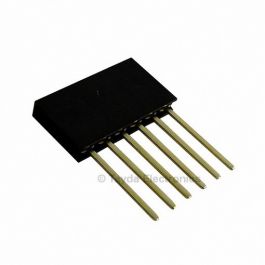
https://www.taydaelectronics.com/stackable-header-6-pins-2-54mm.htmlGet It Fast - Same Day Shipping
Price: USD 0.14
Link: Stackable Header 6 Pins 2.54mm
https://www.taydaelectronics.com/stackable-header-8-pins-2-54mm.htmlGet It Fast - Same Day Shipping
Price: USD 0.15
Link: Stackable Header 8 Pins 2.54mm
Don’t be tempted by the Right-Angled 10pin box header, it’s the wrong way around

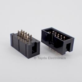
https://www.taydaelectronics.com/connectors-sockets/box-header-connectors/10-pin-box-header-connector-2-54mm.htmlULO Group - Get It Fast - Same Day Shipping
Price: USD 0.14
Link: 10 Pin Box Header Connector 2.54mm 2*5pin
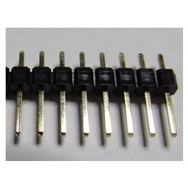
https://www.taydaelectronics.com/connectors-sockets/pin-headers/40-pin-2-54-mm-single-row-pin-header-strip.htmlGTK - Get It Fast - Same Day Shipping
Price: USD 0.15
Link: 40 Pin 2.54mm Single Row Pin Header Strip
#62 — Fox · 2021-04-21
Attention: DIY boards are back in stock for SHUTTER as well as my buffered Mults.
PM me for details. I’ll PM the folks who messaged me too late.
Robbertunist wrote:
Don’t be tempted by the Right-Angled 10pin box header, it’s the wrong way around
>>>
You can make it work if you solder it to the bottom of the board instead of the top. This will make the module deeper but it will work.
Robbertunist wrote:
OK, after about an hour of fucking about, this should be it.>>> https://www.mouser.de/ProjectManager/ProjectDetail.aspx?AccessID=c83f08b2c0
Thanks Robin!
If you can still edit the cart, I have a few suggestions:
- 100nF caps are 5.08mm spacing (not 2.5mm) or use Tayda below.
- I recommend 1/4watt for all of the resistors. Mouser has been out of 1/4watt 499R for months now.
- Remove the duplicates from Tayda (10-pin shrouded, stackable headers)
Most of the parts can be found at Tayda for cheaper in smaller quantities, so I also would like to suggest getting these from Tayda: 1K, 20K, 100K Resistors TL072 CD4053 7805 1N4001 10uF electrolytic 100nF 330nF 6 pin stackable header 8 pin stackable header 10-pin Shrouded
I do not recommend PJ302M jacks from Tayda.
#63 — meudiademorte · 2021-04-21
really love mine!
https://www.instagram.com/p/CN7a21OnbzT/
https://www.instagram.com/p/CN7_jo3HMij/
#64 — Fallinggirl · 2021-04-26
Hi Fox,
I LOVE Shutter. Are there any assembled units still available? I’m so impressed by your work.
#65 — Fox · 2021-04-26
I have parts in the mail. I’ll PM you.
#66 — meudiademorte · 2021-04-27
Its getting my best friend
https://www.instagram.com/p/COLKQn5KIuD/?igshid=bzzuorfqsrew
#67 — SleazeeVulture · 2021-05-19
Interested in a built module if there is any to be had. Looks great.
#68 — Agawell · 2021-05-19
try dm’ing Robbertunist - I’m pretty sure he had a few available a few days ago - he is in EU!
#69 — Fox · 2021-05-19
SleazeeVulture wrote:
Interested in a built module if there is any to be had. Looks great.
Shipped
Agawell wrote:
try dm’ing Robbertunist - I’m pretty sure he had a few available a few days ago - he is in EU!
I should see if he needs more boards.
#71 — Robbertunist · 2021-05-20
Thanks for thinking & suggesting me here Jim @Agawell

SleazeeVulture (I love that name!) is in Boston so shipping from Berlin is a no-no. Anyone is Europe or elsewhere is welcome to contact me if you’re looking for a built one & you want to avoid Import customs for instance.
Yes, there’s still 2 on hand: one built; one waiting for 6172s & the bypass 100n film caps.@Fox
I’ve been meaning to write to you since I saw @rempesm’s recent video posts of a module that’s your design (I’m sure it’s a filter) & maybe another one that you’re both maybe collaborating on, the videos were really cool
Talk soon, Robin
#72 — hewed · 2021-05-23
I’d like to order 2 PCB sets if you’ve still got some. I’m checking with another Australian if they want to order one as well so the shipping cost is more tolerable.
Any rough number on shipping to Sydney, Australia?
And do you have any other units that I could think about adding to the order?
#73 — Fox · 2021-05-23
hewed wrote:
I’d like to order 2 PCB sets if you’ve still got some. I’m checking with another Australian if they want to order one as well so the shipping cost is more tolerable.
Any rough number on shipping to Sydney, Australia?
And do you have any other units that I could think about adding to the order?
No problem, I’ll just respond to your PM.
#74 — Grain · 2021-05-26
Hey Fox, I’m interested in a DIY PCB set if you have available? Thanks!
#75 — Fox · 2021-05-26
I have more on the way, so I will put your name down and contact you once they’ve arrived.
#76 — Dr_Rek · 2021-05-27
PM’d about an order too. Glad I finally figured out where to order this. Of course it was the LZX forum I had neglected for months.


#77 — Grain · 2021-05-27
That’s great thanks!
#78 — vhsdestroyer · 2021-05-28
Hey fox do you have the passive splitter available as a pcb?
#79 — Fox · 2021-05-28
I can get more made if people are interested. I’m making another big order of boards soon, so I’ll toss those on there.
#80 — Maitojano · 2021-06-10
One DIY set for me please.
#81 — crixmadine · 2021-06-16
Please put me on your list for a built Shutter. Thx!
#82 — phosphenes · 2021-06-16
Just got mine built up and I have to say I’m blown away by it! It’s really powerful and intuitive for such a small module. Everyone should get one!
#83 — jimfetterley · 2021-06-21
I’ll take a built Shutter, please!
thanks,
jim
#84 — Fox · 2021-06-21
Messaging…
… (need 20 characters)
#85 — circuitfluid · 2021-06-28
Hello. I’m interested in a built module.
#86 — vhsdestroyer · 2021-07-06
Hey fox, do you have a pcb panel set available?
#87 — Fox · 2021-07-06
Sure do. I’ll PM you.
#88 — Analogmonster · 2021-07-11
Hi Fox I just requested a veil pcb set, can I have a shutter pcb set too please thanks
#89 — hewed · 2021-10-13
I’ve got v3.5F of the PCBs rather than the v3.3F shown in the build guide. V3.5F has a few holes that the v3.3F does not, Is there a v3.5F diagram for the optional section showing where the diodes should be soldered? Thanks
#90 — Fox · 2021-10-13
In v3.5F the optional diodes have been made mandatory and are now located on the frontside of the board. Follow the silkscreen and the module is complete.
#91 — hewed · 2021-10-13
That makes things easier. Thanks for the quick reply!
#92 — Whelm · 2021-11-03
Just a heads up, the BOM at the top of the page is inaccurate, at least for the V3.4F boards I received. Most important is that the BOM calls for 6 1N5711 diodes, while the boards need 12. Also calls for 23 499R resistors, I only found spaces for about half that many.
Luckily I had enough parts in stock but just hoping to save someone else an extra Mouser order.
#93 — Fox · 2021-11-03
You’re right, @Whelm.
The post is no longer editable so the above will forever be missing the rev info (v3.3F FYI).

Here are the BOMs for the other two revisions. v3.5F is the current and/or final revision. BOM for SHUTTER v3.4FQtyValueParts1330nC1510u/25vC2, C6, C23, C24, C2618100nC3, C4, C5, C7, C8, C9, C10, C11, C12, C13, C14, C15, C16, C17, C18, C19, C20, C21121N5711D1, D2, D3, D4, D5, D6, D7, D8, D9, D10, D11, D1221N4001D13, D14268RFB1, FB21CD4053IC16LM6172IC2, IC3, IC4, IC5, IC6, IC81TL072IC713PJ302MJ1 – J8, J10 – J14110-PIN_PWR2J911100KR1, R2, R3, R4, R5, R6, R30, R31, R32, R48, R51181KR13, R14, R15, R16, R17, R18, R33, R34, R35, R36, R37, R38, R39, R40, R41, R42, R43, R44120KR2814.99KR2914499RR7, R8, R9, R10, R11, R12, R19, R20, R21, R45, R46, R47, R49, R5017805U31B100KVR11PCB/Panel Set-110-16 Pin power ribbon-133.5mm jack nuts-1Transparent Davies knob-16-pin stackable header-18-pin stackable header-1single row, male 40-pin header- BOM for SHUTTER v3.5FQtyValueParts17805U3110-Pin Header BoxJ911100KR1, R2, R3, R4, R5, R6, R30, R31, R32, R48, R5118100nC3, C4, C5, C7, C8, C9, C10, C11, C12, C13, C14, C15, C16, C17, C18, C19, C20, C21510u/25vC2, C6, C23, C24, C26151KR13, R14, R15, R16, R17, R18, R36, R37, R38, R39, R40, R41, R42, R43, R4421N4001D13, D14121N5711D1, D2, D3, D4, D5, D6, D7, D8, D9, D10, D11, D12120KR281330nC114.99KR2917499RR7, R8, R9, R10, R11, R12, R19, R20, R21, R33, R34, R35, R45, R46, R47, R49, R50268RFB1, FB21B100KVR11CD4053IC16LM6172IC2, IC3, IC4, IC5, IC6, IC813PJ302MJ1 – J8, J10 – J141TL072IC71PCB/Panel Set-110-16 Pin power ribbon-133.5mm jack nuts-1Transparent Davies knob-16-pin stackable header-18-pin stackable header-1single row, male 40-pin header-
#94 — sean · 2021-11-03
Now that you have a bunch of modules out, may be time to start compiling some of that info somewhere like Github, where versioning can be more easily updated?
(Or maybe a mod here can just help with the edit in the above post?)
#95 — Fox · 2021-11-03
Definitely. I’ve been working on a website too, so it will be nice to have all of the scattered info centralized. And yeah, Github is part of that transition.
#96 — sean · 2021-11-03
Looking forward to it. Keep up the good work!
#97 — janhagel · 2021-12-08
hi! are pcbs available at the moment?