Sync extraction circuit
Category: Unknown · Tags: cadet, sync · Posts: 41
#1 — esnho · 2021-10-09
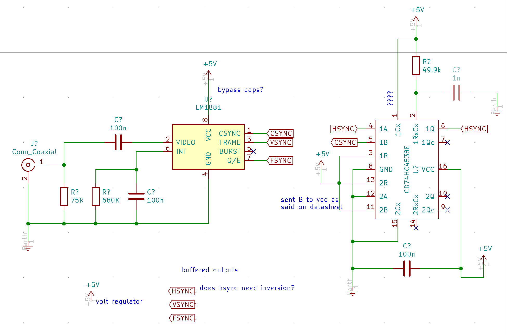
Hi, today I tried to write down a circuit that should extract vertical and horizontal syncs from composite signal or from a standard LZX sync signal.
I looked at Cadet I and Cadet III schematics to understand the main parts.
I don’t want to generate sync signals, I want to get vertical and horizontal sync out of my system to send them to VCO, LFO, S&H, etc…
I’m not sure about the horizontal sync extractor circuit, can someone take a look at it?
#2 — vhsdestroyer · 2021-10-09
If you get this sorted I have a schematic for an LTV clone based on cadet schematics that this could be applied to.
#3 — creatorlars · 2021-10-09
Looks good!
100n bypass cap for LM1881 and in general any V+ or V- pin on every IC. Place it adjacent to the power pin.
If the goal is to reset VCO, S&H, etc. then you do not really need the monostable part (74HC4538.) Just use the CSYNC output as HSYNC. The periods during which CSYNC looks different from HSYNC are during scanlines in the vertical blanking interval (meaning we never see them, any signal in those periods is removed at the output encoder.)
So in your cases listed (resetting a VCO), you can remove the 74HC4538 and just use CSYNC as HSYNC.
Cases in which you’d need the monostable include a genlock clock PLL circuit (like Cadet I).
LMH1980 is the preferred sync separator part for Gen3 stuff, if you care about HD syncs! It also has separate HSYNC output, which is handy. Just follow the circuit in the datasheet. It only comes in an SMT package size though.
re: Buffered outputs… these days we strongly recommend you include rear video sync input/buffered pass thru like this on each module that needs it, and just include HSYNC/VSYNC/OFF switch on the frontpanel (rather than patching HSYNC and VSYNC around). That would then select from the LM1881 TTL outputs to control whatever switch is in your VCO circuit directly. This is how the new LZX oscillator works for example – there is a frontpanel sync input, but it is OR’ed with the HSYNC/VSYNC being generated by the sync extraction circuit internally. I should post some application examples.
#4 — creatorlars · 2021-10-09
If you do want the buffered syncs like Cadet I, follow something similar to the output buffers used there (attenuate to 1V, buffer with video opamp.)
#5 — esnho · 2021-10-09
creatorlars wrote:
If the goal is to reset VCO, S&H, etc. then you do not really need the monostable part (74HC4538.) Just use the CSYNC output as HSYNC.
Thanks Lars, this is a very useful information! My goal is to have patchable sync sources in my system, I don’t have any source of sync except a Vidiot and I can’t build, for example, a Castle VCO because I don’t have compatible sync sources.
One day I’ll probably try to build my VCOs or ramps but not before try to build one of those available out there.
creatorlars wrote:
LMH1980 is the preferred sync separator part for Gen3 stuff, if you care about HD syncs! It also has separate HSYNC output, which is handy. Just follow the circuit in the datasheet. It only comes in an SMT package size though.
Oh yeah, I read that you said something about this change, sincerely I’m a bit scared of SMTs (I’ve got an art degree

nothing techie) on the other hand the circuit for LMH1980 looks easy to setup.
I guess is also possible to leave the HD detect flag disconnected without any issue; then remove C2, Q1, R3, and R10 from the equation.
creatorlars wrote:
100n bypass cap for LM1881 and in general any V+ or V- pin on every IC. Place it adjacent to the power pin.
Sure! I know this is a mantra for every IC, IDK I’ve placed a question mark in the draft, check this other scheme, I used them!
Update, the panel is coming. > > > And I take the initiative and post here the schematics for this module: >creatorlars wrote:
these days we strongly recommend you include rear video sync input/buffered pass thru like this on each module that needs it
Got it, I’ll try to place RCA I/O on the back of the board, I promise!
#6 — esnho · 2021-10-09
vhsdestroyer wrote:
If you get this sorted I have a schematic for an LTV clone based on cadet schematics that this could be applied to.
What’s an LTV? I tried to figure it out but I failed.
#7 — creatorlars · 2021-10-10
Cool!! It sounds like a simple LM1881 circuit is exactly what you need then.
If you use the LMH1980 I would keep the HD/SD filter as in the application circuit – it applies some filtering in SD modes to prevent glitches. But if all you need is SD syncs for DIY project, LM1881 is perfect.
#8 — esnho · 2021-10-10
Even if I’m not planning to have HD units soon, I want to go through the HD route, I’ll use PCB manufacturer SMT placing service, I guess.
I’m keeping the HD/SD automatic filter, seems smart.
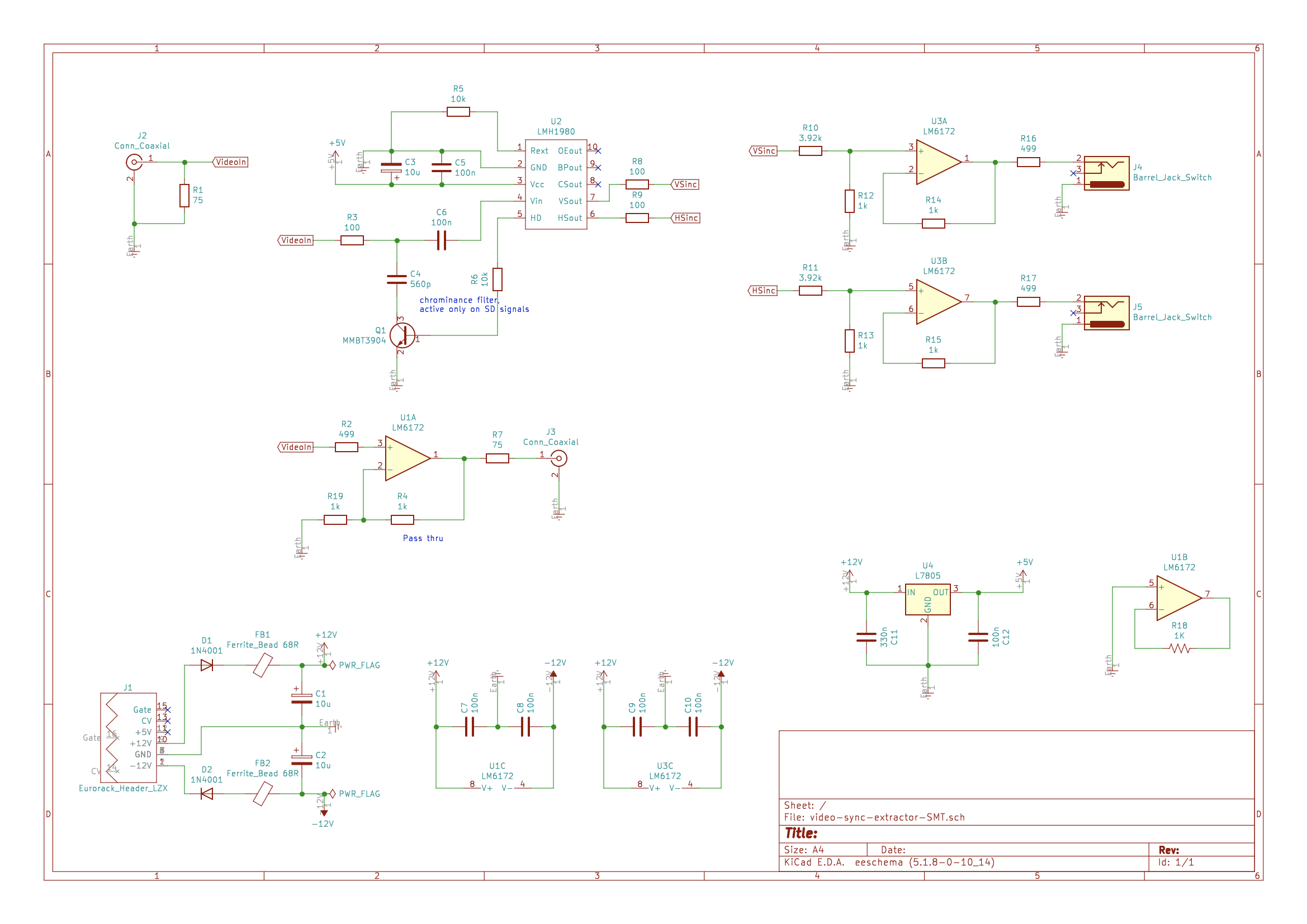
What I can’t understand is what voltage LMH1980 outputs, from the datasheet looks like it’s Vcc dependent, I can’t understand if using 5Vcc it outputs 5V as sync signal… should I keep the Cadet’s voltage divider on the output?
That would results in something like this:
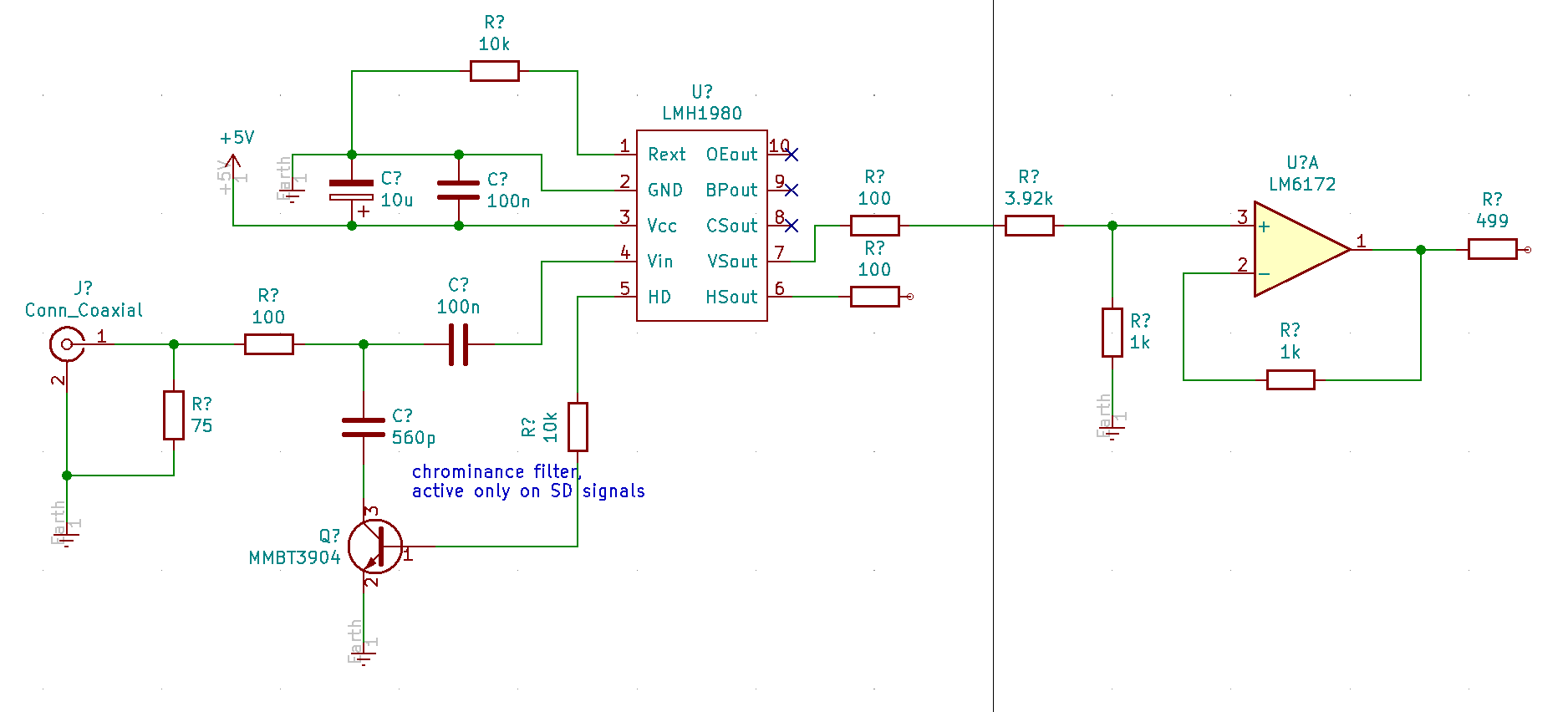
The circuit is missing the pass thru for input signal, and details like power and jacks on the output buffer section
#9 — esnho · 2021-10-10
I kept drawing and the circuit should be complete.
I’m not sure about C3 and the voltage dividers on buffered outputs but looks good!
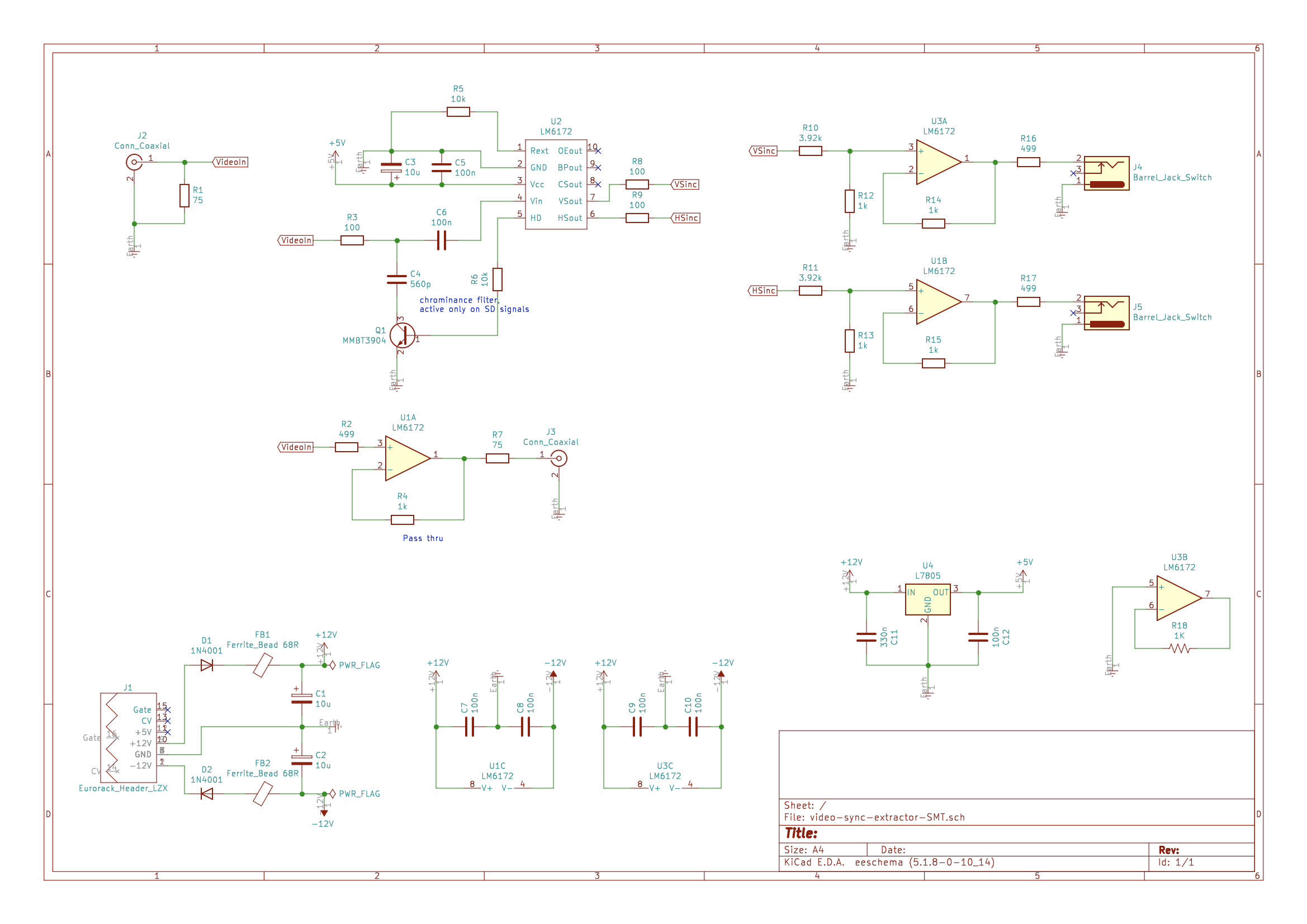
I have to think about the PCB layout but probably there’s room to duplicate HSync and VSync.
#10 — Fox · 2021-10-10
Hey esnho, I see that you’ve buffered the “videoin,” but need to apply a 2x gain (at U1A) because of the 75R termination resistor (R1).
#11 — esnho · 2021-10-10
Thanks Fox!
R19 should fix it

#12 — esnho · 2021-10-10
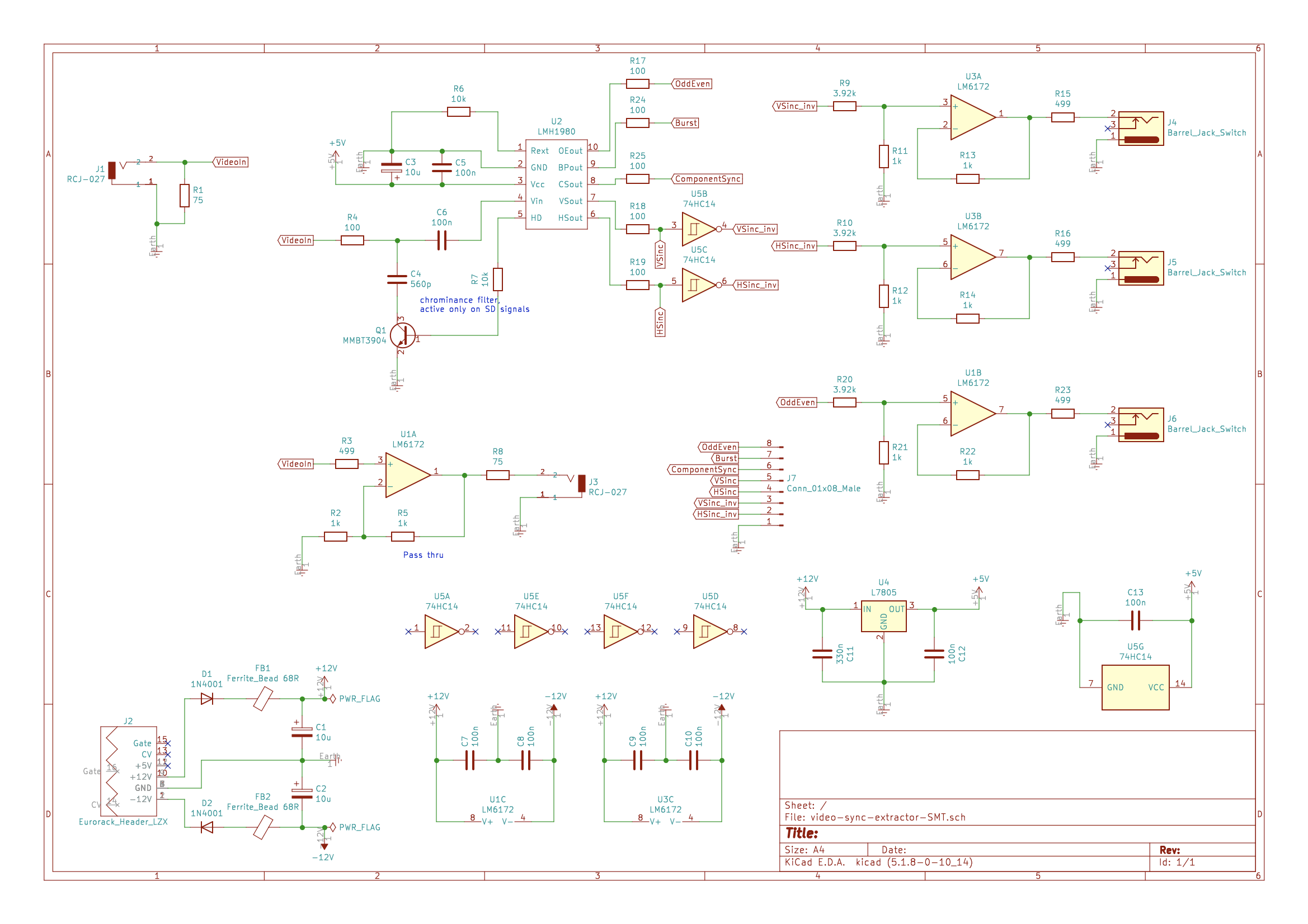
I noticed that the sync separator got a wrong label… Was labeled as an OpAmp
This is a version with the label corrected, and with a better choice in LM6172 placements
#13 — Z0NK0UT · 2021-10-10
LTV = Liquid Television
#14 — creatorlars · 2021-10-10
Good work. You can omit R8 and R9 – those are in series with R10 and R11, and aren’t really doing anything in this instance (just have R10 and R11 adjacent to those pins instead.)
In Cadet Sync Gen, Visual Cortex, and Video Sync Generator, the frontpanel sync outputs are inverted, so that they appear as a positive pulse to VCOs. I would use 74HC14 inverters to invert between the LMH1980 and the output buffers if you want to do it that way. A population option is at least a good idea for the PCB design, if you’re not sure.
#15 — esnho · 2021-10-13
This is a very useful suggestion, and I have to update the schematics and start again with the PCB design

Thanks!
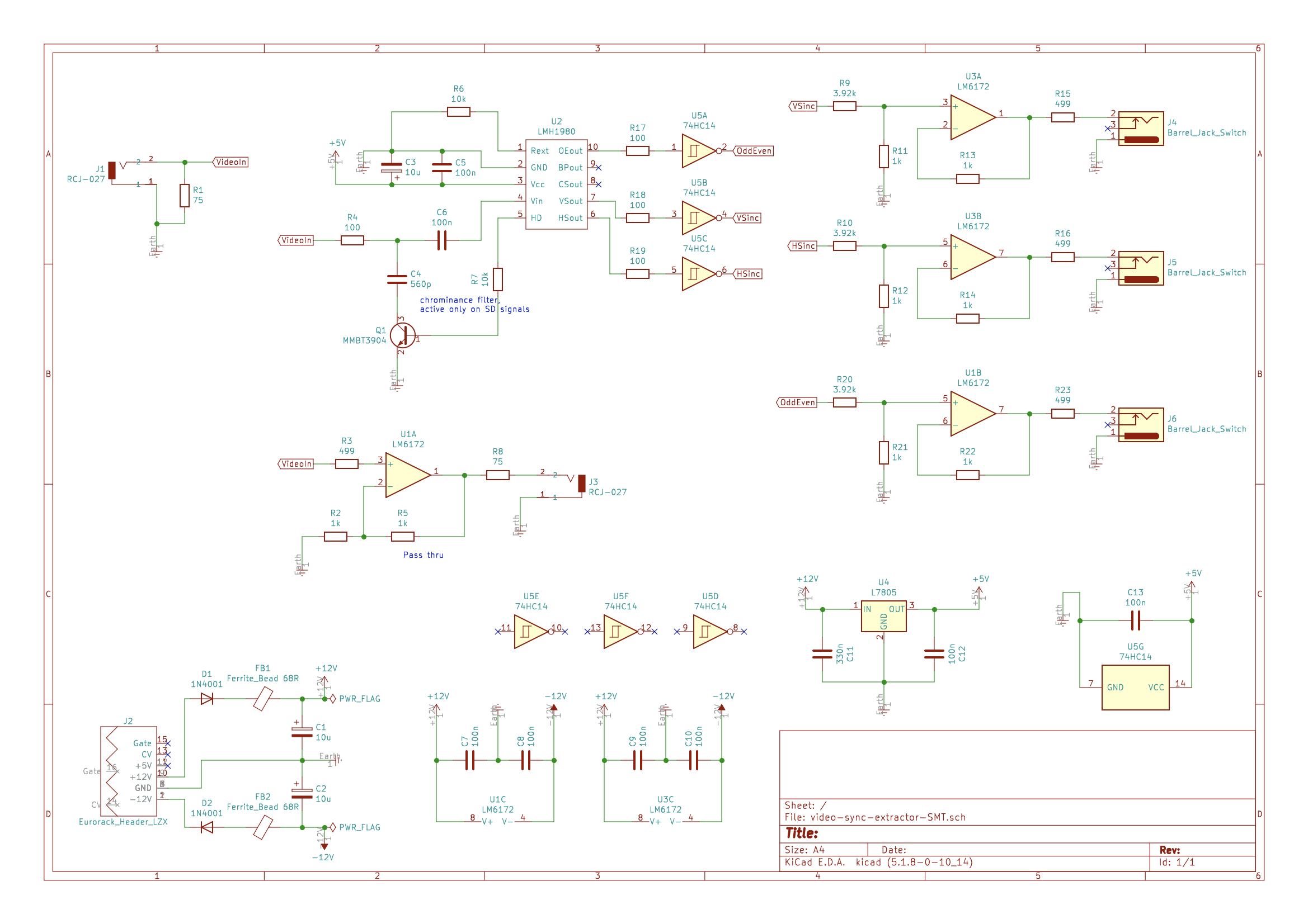
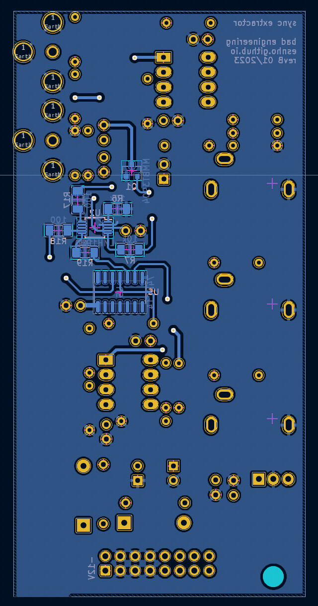
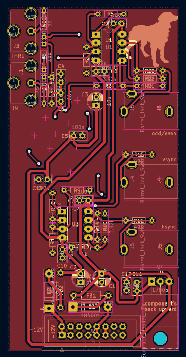
#16 — esnho · 2021-10-16
I inverted outputs and added odd/even to my outputs for crazy syncs.
I hope I did not add any flaw.
The layout is in vertical style, the PCB is 40mm depth, the RCAs female jacks points downwards, this means that the used RCA cable changes the module depth.
I had to draw RCAs footprints, I want to double check them before send the project out to print.
#17 — dubpixel · 2021-10-16
This is awesome.
I never finished a similar design I had been working on. I got busy with work & still need to solve a similar issue in part of my rig.
Lmk if you are gonna sell PCBs, I’ll pick one up for sure.
Also always a reminder I should stop using Eagle and learn kicad- your 3D looks great.
#18 — creatorlars · 2021-10-16
Looks good!!
For the Odd/Even out, let’s talk about the inversion –
The output from the LMH1980 will be high when you are in the first field or you have a progressive video format.
Odd/Even inverted (what you have now)
This is an interesting case because the output state only goes high if there’s an even field present. That means it is also a “interlaced/progressive detect.”
Odd/Even non-inverted (what you probably want)
If you don’t invert that output, the output now transitions from low to high at the start of a new frame. This is what is meant by “FSYNC” on Visual Cortex for example. This start of frame event is really important if you want to send a sequencer a “frame clock” that only transitions at the start of an interlaced frame. If you sync a sequencer with what you have now, it would be half a frame off.
In both cases this output is useless in progressive video formats – you’d want to use VSYNC instead. So a mux (ODD/EVEN OUT = VSYNC in redundant states) would be a good idea if this were intended as a product design where you were trying to eliminate null output states. But not necessary.
#19 — esnho · 2021-10-16
Thanks Lars for the informative feedbacks!
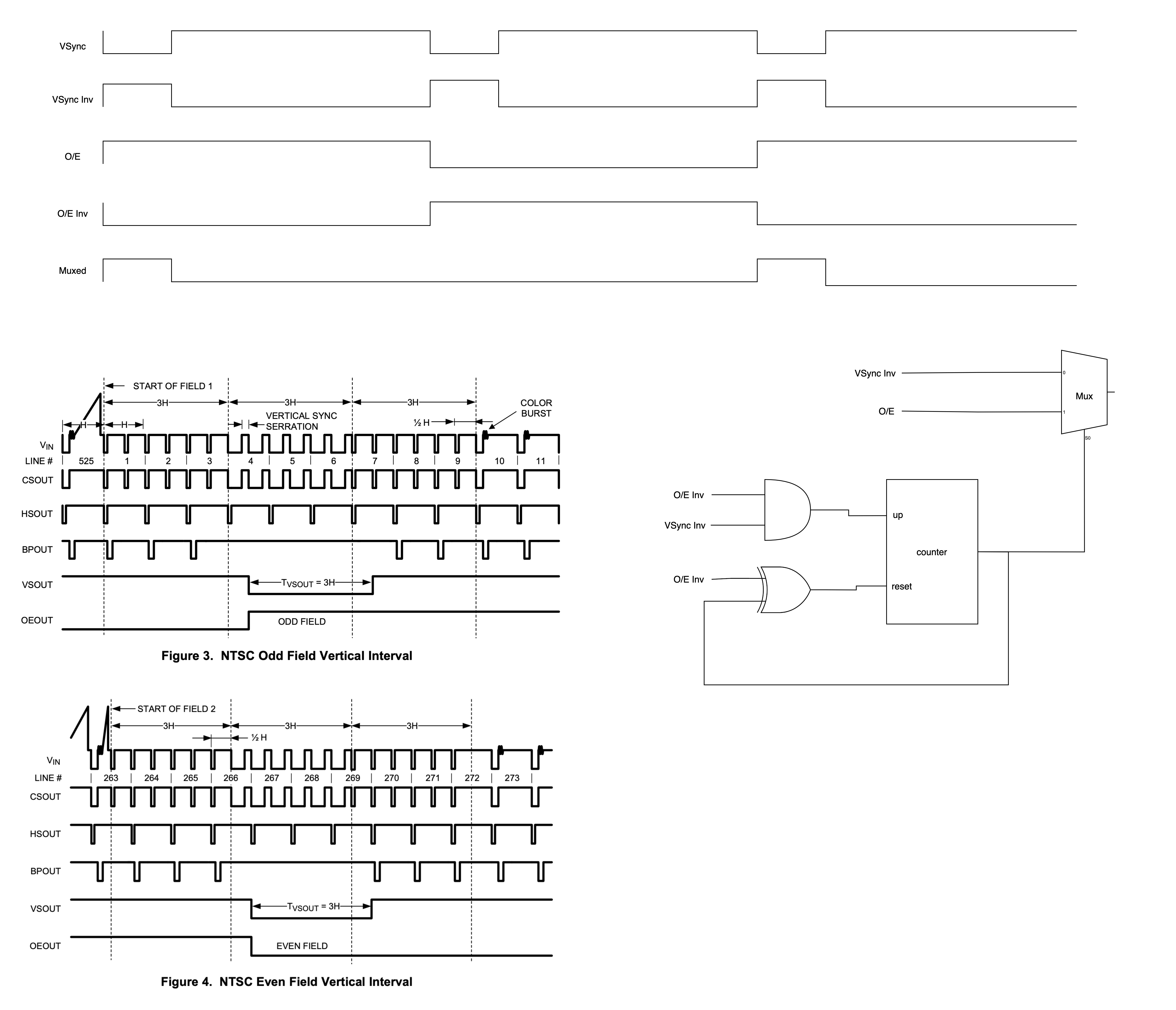
I was looking at the timing diagrams trying to imagine the mux logic.
A = Odd/Even | Vsync
B = Vsync
I’d start sending Vsync to both A and B, if the circuit detects an interlaced frame, the muxer start sending Odd/Even to A and Vsync keeps going to B.
For sure this little logic doesn’t support hot sync source swap (from i format to p) and requires a manual reset (on/off), and starts to add complexity to what I thought be an easy circuit
Probably here I need:
- a muxer, preferably with only two inputs
- a counter, with less pins as possible
I think that is possible to use booleans to switch back from “interlaced state” to “progressive state”, but probably I need to fully understand the use cases of the syncs and odd/even, below a logic that could work keeping the “state” dynamic, but I’m not sure.
It uses an AND and XOR gates to flip a counter that controls the muxer, maybe is totally wrong, is the first time I try to design such logic.
#20 — esnho · 2021-10-16
Thanks @dubpixel!
I’ll keep you posted in this thread, as you can see is getting longer than I though

#21 — creatorlars · 2021-10-19
esnho wrote:
to use booleans to switch back from “interlaced state” to “progressive state”, but probably I need to fully understand the use cases of the syncs and odd/even, below a logic that could work keeping the “sta
Yeah, It would be easier to have this kind of functionality in a CPLD based device – for this module, what you have is already good. I’d just send O/E out the same as the last schematic, but non-inverted.
On the PCB itself, I’d put thruhole pads / pin header for “non inverted” and “inverted” versions of all the different syncs coming out of LMH1980 if you’ve got the room. That makes it easy for a DIY’er to experiment with the signals. For example, Burst Gate is handy if you’re doing a video input amp/DC restore circuit, and regular (non inverted) versions of VSYNC and HSYNC would be handy if you’re doing a DIY encoder or something.
Another easy extension would be an LED that’s driven from the HD/SD flag, that way you’ve got some kind of format detector on the panel. Not really necessary though.
#22 — esnho · 2021-10-23
Lars thanks for the great support, I’d love to put a led on the HD detector but I guess I’d need a new op-amp to buffer the signal and avod issues on chrominance filter

BTW I did my best to create a breakout for the various sync signals, here it is! They are all unbuffered but I guess they are enough as expander/diy option.
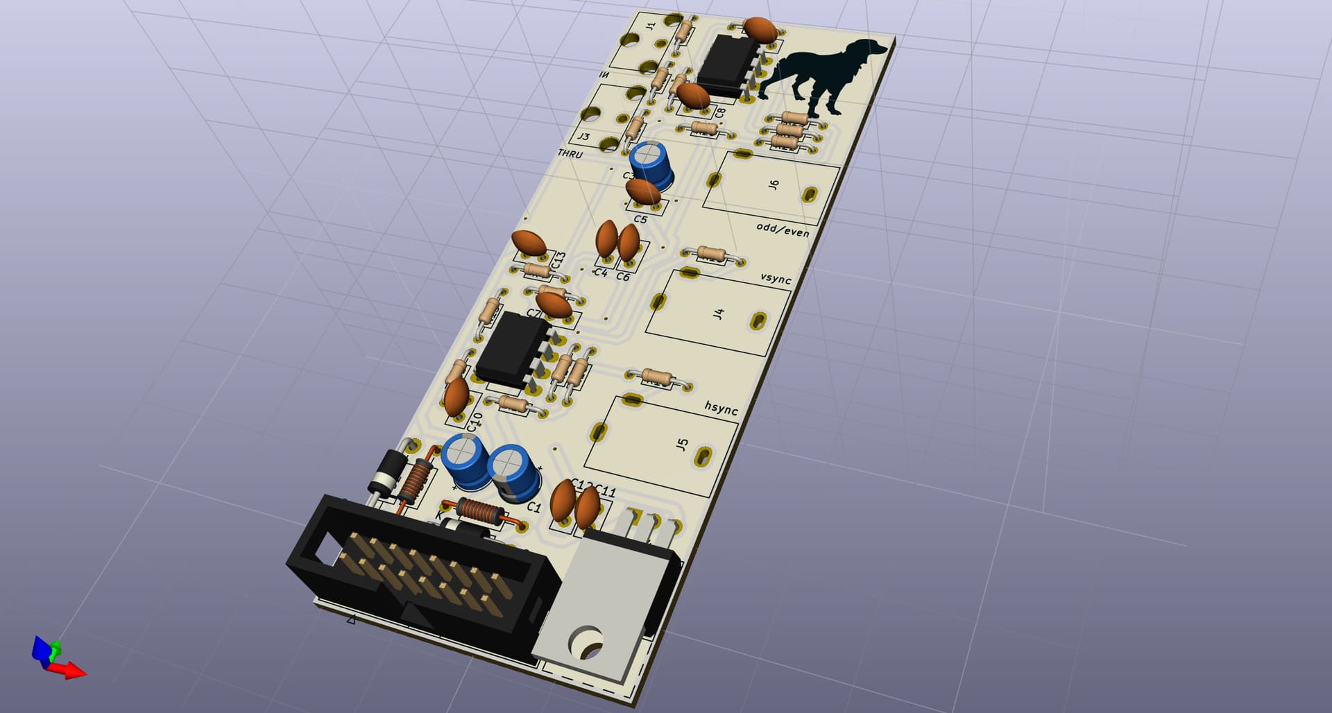
#23 — esnho · 2021-10-23
Aaaand here’s a preview with the panel
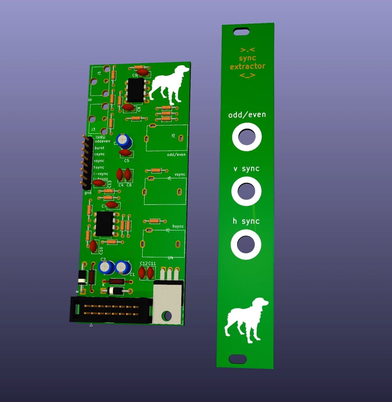
#24 — esnho · 2021-10-23
@vhsdestroyer@dubpixel do you want to help me test this?
I don’t have a syncable VCO at the moment (that’s because I didn’t have a sync source
)
So I only can assembly it and test with the oscilloscope.We can talk privately if you want.
#25 — dubpixel · 2021-10-23
I’d love to. Sending DM
#26 — joem · 2021-10-23
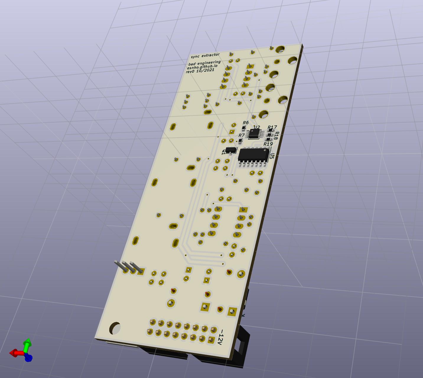
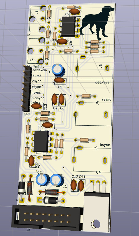
Is the LMH1980 on the other side of the board? I don’t see the footprint in your pics.
#27 — esnho · 2021-10-23
Yes! It’s on the other side with some resistors and the 74HC14, they are surface mounted and inspecting other modules is realise that to put them on the ground plane side can be a smart move.
#28 — dryodryo · 2022-02-25
Luca! Did you ever get this finished and working?? Because I want what you have! I want to incorporate vertical interval switching throughout my system, and to do that I need to extract vertical sync. I would be quite happy to commission you to build one of these, as I am not competent to do it myself.
If not, then maybe I can make something happen with the Chromagnon V output… I assume these are horizontal and vertical drive sawtooths? I might be able to convert to vertical interval trigger by putting it through a comparator and/or sample-hold.
Thanks
Aaron
#29 — esnho · 2023-01-03
Hi!
I’m back on this, the last year I’ve lost the focus on DIY projects.
I’m reviewing the board and hopefully improving the traces.
I’m not sure about the packages sizes, I’m going with KiCad’s “Resistor_SMD:R_1206_3216Metric_Pad1.30x1.75mm_HandSolder” I hope they are good.
#30 — esnho · 2023-01-03
Hi,
the project is still in deep alpha state, I’ve printed the first run of boards and realised that was not possible to easily solder everything, at least for me…
To be noted that is not a ramp generator, but only sync extraction, this means that the jacks will output just small trigger pulses.
#31 — esnho · 2023-01-03
The board now is 50mm deep, previously was 40mm.
I’ve removed the breakout to dismiss a couple of SMD resistors, and simplify (hopefully) the build.
#32 — Boneoh · 2023-01-03
This is cool! Keep us posted, maybe we can do a group buy when you order the boards!
#33 — dryodryo · 2023-01-03
Very cool @esnho! I’ve been using a Syntonie VU009 video-synced sawtooth oscillator through a comparator, and that’s working. But a simple sync extractor would be more elegant.
#34 — esnho · 2023-01-05
Hey, that’s a smart approach!
I’m slow but working on this, I’m scared AF by the SMD part, but if it works it should be interesting for HD timings as well.
@Boneoh sure, please follow this thread

#35 — dryodryo · 2023-01-05
For me, it absolutely needs to support 1080i59. My whole studio uses that format.
#36 — esnho · 2023-01-06
I don’t have the possibility to test if it’s actually supported, my whole setup is PAL, on the paper it should, but I can’t confirm it.
Someone have to take the risk and test it.
At the moment of writing I should be considered as an enthusiast/hobbyist/DIYer not a business man.
As you can see from above I changed my design from SD only to SD/HD support, it would be great if it works!

#37 — creatorlars · 2023-01-06
esnho wrote:
As you can see from above I changed my design from SD only to SD/HD support, it would be great if it works!
Looks good to me! The LMH1980 is a great part, and what we’re using in all the LZX Gen3 modules, so should be compatible with the 15 standards including 1080i5994. You are buffering with high speed opamps, so there shouldn’t be any issue with the narrower pulsewidths of the HD syncs.
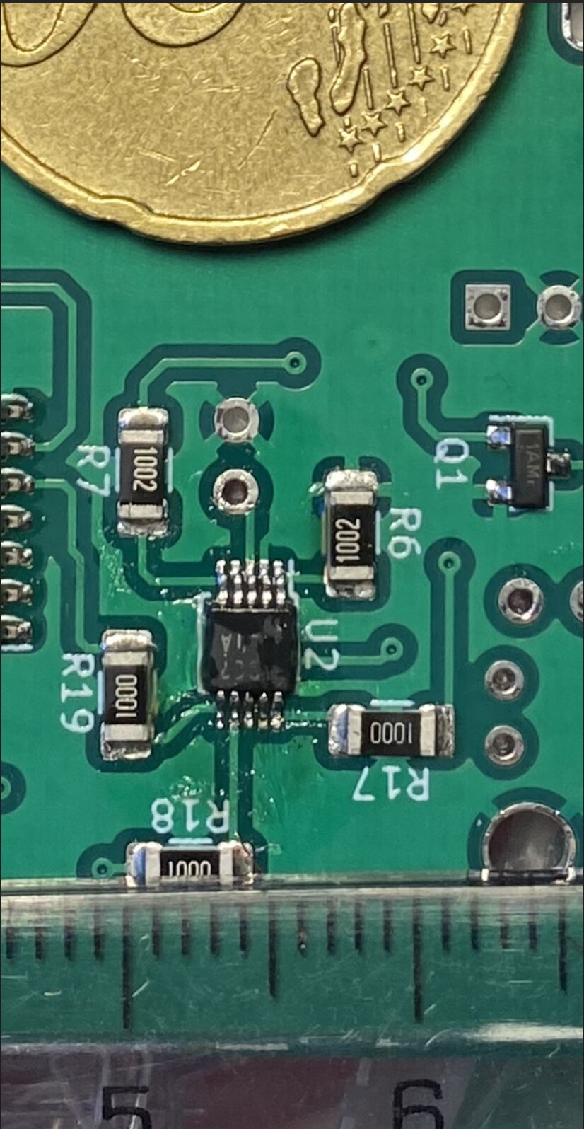
#38 — esnho · 2023-01-28
Work in progress, I’ve received revB boards, and successfully soldered the harder component (the IC at the center), moving to the others.
#39 — dryodryo · 2023-01-28
Fantastic, Luca! Is this going to be 4HP? Saving space in the rack for this!
#40 — esnho · 2023-01-29
Yess, I’m working on a vertical PCB with 4hp panel, it’s 50mm depth + RCA connectors on the back.
I’ve just realised that I’ve forgot to order a component (330nf caps), I though I had them
.
I’ll be able to test it in February, if everything works as expected I’ll send the PCB to a couple of person I’m in contact with for testing.
I hope the test will be successful!
#41 — dryodryo · 2023-01-29
That is so awesome! I can’t wait. This will greatly simplify my process for quantizing modulation to frames/fields.