Conversion to LZX RGB format
Category: Unknown · Tags: — · Posts: 56
#1 — dryodryo · 2021-10-20
Hey there,
What do I need to do to convert HD video to the LZX RGB standard? My understanding is that the LZX 1V standard is unique. Before hitting LZX RGB inputs, any signal is going to need to be massaged: voltage scaling, DC restoration, sync strip, etc. I saw in another thread that Cadet III performs this function. But of course I did not see them for sale. What are my options currently?
What is the plan for Gen 3? A decoder module that can accept YUV would be good enough for my purposes at this time, but of course we need to get other formats in as well. I propose separate decoder modules for analog & digital signals. The less complicated the better, for both designers and users of the modules. I’d love to see an analog decoder supporting YUV and VGA. RGBS, RGBHV, and RGsB would be great, but not top priority. A digital decoder would need to support HDMI and SDI. DVI-D would be nice, but not essential.
Thanks!!
Aaron
#2 — creatorlars · 2021-10-20
TBC2 is the module we have developed for this purpose.
#3 — rempesm · 2021-10-20
dryodryo wrote:
What do I need to do to convert HD video to the LZX RGB standard?
It would take a circuit being designed and manufactured that does those functions. There is not a standalone Eurorack format module that exists that does what I think you’re getting at, i.e. an HD component input amp with no intervening frame buffer.
I’m curious to hear about your proposed workflow with these myriad input formats or your desired outcomes from a video synthesis instrument. It seems like minimal to no frame delay is critical in your process which I’m not quite understanding due to lack of context–do you have any current work you could share with us that gives a sense of how you plan to approach the instrument? Some frame delay seems impossible to avoid in my own practice but I’m not doing anything where user input per individual frame is critical or can’t be compensated for.
#4 — joem · 2021-10-20
dryodryo wrote:
I saw in another thread that Cadet III performs this function.
I’m pretty sure the Cadet III does not do what you’re looking for. First, it’s SD-only since it uses a LM1881 (as far as I can tell, that’s only for NTSC/PAL, both of which are SD formats). But also it’s not RGB, it just converts a composite signal to a luma (brightness) signal.
The Syntonie VU003 is closer to what you want, since it’s YPbPr, but it too is SD-only because of the LM1881.
#5 — pbalj · 2021-10-20
From the LM1881 datasheet:
The integrated circuit is also capable of providing sync separation for non-standard, faster horizontal rate video signals.
Not sure the range of signals it will decode sync from, but it should do some hd I would think.
#6 — dryodryo · 2021-10-20
creatorlars wrote:
TBC2 is the module we have developed for this purpose.
TBC2 looks great, at least for component signals. A post-release firmware update to support VGA resolutions up to 1080i would make it complete. But if I am not mistaken, there is no way to bypass the frame store. Forgive me if you already answered this question on FB. But can TBC2 be used as a simple decoder for synchronous sources?
And of course, TBC2 doesn’t address the need for HDMI and SDI input into an LZX system. This can be handled by external conversion boxes, but this is sub-optimal for many reasons, including portability. Ideally a modular system would have everything needed in one case with a unified architecture, power, etc.
Thanks!
#7 — rempesm · 2021-10-20
dryodryo wrote:
But can TBC2 be used as a simple decoder for synchronous sources?
The inputs are hardwired directly into the frame buffer, so no. What you are describing is an input amp module that doesn’t exist and would need to be designed and manufactured.
dryodryo wrote:
And of course, TBC2 doesn’t address the need for HDMI and SDI input into an LZX system. This can be handled by external conversion boxes, but this is sub-optimal for many reasons, including portability. Ideally a modular system would have everything needed in one case with a unified architecture, power, etc.
That would be ideal, wouldn’t it? For now, I think you’ll have to use external converter boxes if your workflow necessitates that.
Just circling back to my question above, I’m curious if you could fill us in on your need for a near zero frame delay in a practical context of your body of work or what you’re hoping to literally do with these devices. It might help folks on the forum give you better advice on what you’re trying to achieve that requires such minimal frame delay when some frame delay is usually just a factor of life in video synthesis up to pro broadcast settings.
Not saying there isn’t a need for it if we can understand why.
#8 — dryodryo · 2021-10-20
rempesm wrote:
I’m curious to hear about your proposed workflow with these myriad input formats or your desired outcomes from a video synthesis instrument. It seems like minimal to no frame delay is critical in your process which I’m not quite understanding due to lack of context–do you have any current work you could share with us that gives a sense of how you plan to approach the instrument? Some frame delay seems impossible to avoid in my own practice but I’m not doing anything where user input per individual frame is critical or can’t be compensated for.
One of my core intentions is to play the video synth as a real-time instrument, controlled from a PC via MIDI and DC coupled audio CVs. Latency is a huge concern here. It’s already bad enough that the best audio interfaces available can only bring latency down to ~10 ms, and practically speaking it’s usually more like ~20 ms. Then if we’re going through a TBC, that’s adding at least ~30 ms. So at a minimum we’re looking at two frames of delay between hitting a MIDI key and seeing something change on the screen.
Then it gets even more ugly when we’re trying to generate musical sound and picture at the same time. If the video is being delayed by TBCs etc., and the audio is not, then there will be an A/V sync issue at the capture stage. That could be dealt with by shifting audio in post, but that is a solution to a problem that does not need to exist.
#9 — dryodryo · 2021-10-20
rempesm wrote:
What you are describing is an input amp module that doesn’t exist and would need to be designed and manufactured.
Yes, that’s what I thought, and that’s why I brought it up. There’s a need for this, at least in my use case described above.
I think people may be too comfortable with frame delay as a “factor of life”. I clearly remember a time when absolutely everything in a studio was locked to house sync. TBCs were expensive. Even VCRs weren’t necessarily going through full frame stores… the old U-Matic decks went through 16-line TBCs that introduced almost no delay.
#10 — rempesm · 2021-10-20
dryodryo wrote:
One of my core intentions is to play the video synth as a real-time instrument, controlled from a PC via MIDI and DC coupled audio CVs. Latency is a huge concern here. It’s already bad enough that the best audio interfaces available can only bring latency down to ~10 ms, and practically speaking it’s usually more like ~20 ms. Then if we’re going through a TBC, that’s adding at least ~30 ms. So at a minimum we’re looking at two frames of delay between hitting a MIDI key and seeing something change on the screen.
This sounds like a fun approach but I wonder if you’ve had the opportunity to attempt this workflow with another analog video synth and had this exact problem occur that made it impossible to navigate. If you haven’t, there might be LZX users in your area that you could attempt to try this out to see how much it really creates a problem during the process? It seems like this is a major point of concern for you and I’d be sad to see you disappointed with gear that doesn’t meet specs you’d like it to have.
Can we see any of your current portfolio so we can try to make some helpful suggestions with context on what you’re attempting to use this for in more concrete terms? I get that you want to press a key and have something happen with zero delay but I’m having trouble conceptualizing how two frames would actually present an issue. I’m mainly curious as I’ve personally never encountered another video synthesist whose work was frustrated by two frames of delay and just want to better understand the limitations you seem to be butting your head up against.
dryodryo wrote:
Yes, that’s what I thought, and that’s why I brought it up. There’s a need for this, at least in my use case described above.
Cool, maybe this would be a great opportunity to learn how to design a module that fits your needs and share it with everyone else! I had no idea how to design a module a little over a year ago and found the time to make a Quad S-Video Distribution module I wanted with no formal training. Maybe that’s not in the cards for how you want to spend your time, which is totally understandable. If not, maybe you’d want to personally commission someone to research, design, and manufacture it for you?
I don’t know your circumstances but it’s unlikely a very niche case module will appear on the market by posting an idea about it on a forum–just trying to be real if you’re looking for this module to actually exist. Syntonie’s VU003 is probably a good starting point but the YUV->RGB LZX 0-1V colorspace conversion is different between SD/HD and the sync stripper (LM1881) may need to be a more modern adaptable IC like LMH198x.
dryodryo wrote:
I think people may be too comfortable with frame delay as a “factor of life”. I clearly remember a time when absolutely everything in a studio was locked to house sync. TBCs were expensive. Even VCRs weren’t necessarily going through full frame stores… the old U-Matic decks went through 16-line TBCs that introduced almost no delay.
Sure, it makes sense that when TBCs were expensive that there was more of an emphasis on gear that primarily worked with genlocked inputs. I have ancient gear from the 70s with separate composite sync and composite blanking inputs, even!
Maybe digging into that older gear will get you the result you want? TBC2 is just not the module you’re looking for if you want zero input delay nor can I think of any TBC that has zero delay due to how they work. I’m not an expert on all TBCs that have ever been produced so maybe you have model numbers of examples of some you could share with us?
#11 — dryodryo · 2021-10-21
Thanks, but that Syntonie module is SD only.
The line TBCs I’m referring to are rare these days. But the concept is that they don’t store the whole frame. You need to make bidirectional connections between the TBC and the VCR. The TBC replaces the sync coming from the deck, stabilizing the signal. It also cleans up the raster, performing dropout compensation. That’s an example showing how delaying all signals by at least one frame is just unnecessary. It’s convenient to just feed random wild signals into a frame store, but it’s not always the best solution. Pretty soon you’re in a situation where you need to delay the audio, too, and things get messy and expensive.
As for my own work, you’re welcome to take a look, but what you see there isn’t necessarily indicative of what I am going to try to accomplish in the future. The closest thing would probably be “PSEKELIS”. I created this at CalArts by feeding a prerecorded musical piece into a bunch of gear including a Fairlight CVI, CV-modded Optical Electronics raster processor, Hearne/EAB Videolab II, and ARP 2600.
http://www.dr-yo.com/video_psekelis_hfr.html
#12 — rempesm · 2021-10-21
I don’t think I can help from here as you probably need to find older rare gear or invent newer gear that does what you want at the price point you’re willing to pay. Good luck!
#13 — joem · 2021-10-21
pbalj wrote:
From the LM1881 datasheet:
The integrated circuit is also capable of providing sync separation for non-standard, faster horizontal rate video signals.
Not sure the range of signals it will decode sync from, but it should do some hd I would think.
From the LMH1980 datasheet (emphasis mine):
Advantages of the LMH1980The LMH1980 offers several advantages over the LM1881, including:
-
Lower operating supply of 3.3 V>>- > Wide temperature range of −40°C to +85°C>>- > Auto-detection of the input video format using a fixed-value resistor biasing architecture>>- > > Support for HD tri-level sync separation> >>- > HSync output and HD detect flag output>>- > Smaller package>>>>
That’s why I figure the LM1881 isn’t suitable for HD.
#14 — wednesdayayay · 2021-10-21
I’ve never noticed the delay in any kind of appreciable way
and I love working with memory palace + sensory translator
so I guess I just don’t see this as a problem for my own work
what video synthesis equipment are you currently working with?
#15 — dryodryo · 2021-10-21
wednesdayayay wrote:
what video synthesis equipment are you currently working with?
I am getting back into this field after a long hiatus. But I have experience with the Sandin and Hearne/EAB systems, DVEs, raster manipulation, etc. Plus I was a video editor and videographer, and I’ve been a computer musician and 3D graphic artist for a very long time.
The only reason I am getting back into video synthesis is because LZX is supporting high definition. I would have bought their gear long ago, but I am a snob about HD.

#17 — Marizu · 2021-10-21
I understand exactly what you want @dryodryo and I understand exactly why you want it. I do find that latency becomes more significant for tight rhythmically oriented patches. I am starting a project with a tap dancer, next month, and I know that some elements of this may benefit from low latency response.
People talk about one or two frames latency, but this isn’t what I’m seeing from my Memory Palace or Structure. It’s more than that (there is another thread about this). When I plug into a venue’s projector, that will add some more latency. At a certain point, some types of patches no longer work.
My approach for working around this type of thing is to have the digital stuff going into the Cortex and then trying to add any required snappiness using analogue processing. My desire is to minimise any latency that I can control in order to give myself more options.
I suspect that if you transfer the audio performance elements into the voltage controlled realm, then you may be able to cut down on some of the latency that is intrinsic to MIDI and audio interfaces. This way, your video synth can work from the exact same triggers as the audio.
I get the impression that low latency input is a relatively niche requirement. I don’t know whether the Syntonie VU003 – COMPONENT2RGB could be updated to use the LMH1980 and put an additional Genlock output to the front panel (and possibly the rear, too). By my thinking, that would provide one component input that sends a genlock signal and could bypass any frame buffered encoder sections (Chromagnon etc).
#19 — dryodryo · 2021-10-21
Yes, that was me. I think the episodes have all been taken down from the KPSU site.
#20 — creatorlars · 2021-10-21
I am working on an infographic that clearly sets out some terms and definitions for video latency, but have not had much time to work on it. I think it may clarify this discussion more, and provide a basis for describing what we’re all trying to accomplish here – there are several very different ways that latency is introduced in the signal path in a complex video processing system, and several very different ways in which that becomes relevant – or not – for various user workflows.
This is a fascinating topic that rarely escapes the world of folks who are designing the circuits themselves. It’s important to understand LZX is a “deconstructed video” format – it lets you do all kinds of things to the signal and interface with it in a manner outside any consumer or broadcast gear.
So it can be very hard to have a discussion on latency outside a very specific signal path (which is why we all keep asking for examples of gear being used and techniques being attempted.) Maybe it is easier, if we at least have those details nailed down in context, even if it is for the purpose of theoretical analysis. That way we can have the discussion using words like nanoseconds and microseconds!
#21 — creatorlars · 2021-10-21
So, let’s break down all the complex signal flow steps that introduce latency.
For the purpose of illustration, we have a PC with a mouse, video playback software, an SDI video output card, an SDI to analog converter, an analog to 1V LZX TBC (TBC2), an analog keyer module (FKG3), an analog output encoder module (ESG3), and a consumer grade LCD video monitor with Analog/YPbPr input.
The latency we are measuring is the time it takes between “click the Play button” and “LCD monitor starts to show the frame.”
Each of the following steps introduces latency:
- The USB peripheral drivers poll the mouse and register a click.
- The software registers the click event and process it.
- The software starts buffering a video file into memory until it reaches a threshold at which it decides is safe to start streaming without hiccups.
- The video output card shows the first frame of video.
- The SDI to Analog converter processes the first frame of video and converts it into an analog signal.
- The TBC2 module captures the frame to memory and then waits for the next “house sync” vertical refresh pulse.
- The TBC2 module streams the frame to it’s 1V RGB outputs. Now we are inside the LZX 1V patch.
- The FKG3 keyer module processes the analog signal, transitioning for example, between the image and a synthesized pattern.
- The ESG3 analog encoder converts LZX 1V RGB back into viewable analog video signal.
- The analog video signal is captured by the LCD monitor and converted into a digital bitstream, and written to the monitor’s internal frame store.
- The LCD monitor refreshes, and you see the result.
All 11 steps introduce latency. Now, we can start estimating and measuring in context – the latency between two different steps, for example.
Steps #7 thru #9 are measured in nanoseconds. In this case, the latency is maybe 100ns? No more than a pixel or two. Each analog op-amp in the signal path adds a latency of around 10ns.
For the sake of proportional context, 100ns is about 10000 times faster than even Step #1 (registering a mouse click at 1ms polling speeds.)
And for the sake of argument, steps #1 thru #6 and #10 thru #11 have no effect on the output image you will see. There’s no difference if this was a latency of 1 frame or 100 frames, nothing is changing besides the time it takes for you to see it.
So in this example case, the only significant latency factor is the user interface element – UI response time between click and display. Whether that is relevant and how much it effects your workflow is inherently dependent on your process itself. For example, in a pre-rendered mixdown scenario for recapture, it doesn’t really matter at all. In a performance context where you are clicking the mouse in time with a live audio signal, it matters more. As mentioned above, it is the display or projector that is most likely to introduce an annoying amount of latency in context.
Things only get more complicated or start to effect the resulting image you will see when we are discussing recursion/feedback. And in that case, “low latency = always good” is not true at all. For example, you want at least one frame of latency in order to build up recursive images that stack on top of each other – if it’s less than that, you get more of just an optical smear – also good, but a different technique. Even delaying the recursion (variable programmed latency – frame delay memory) is an important technique.
The recursion latency and total latency are two different things entirely. Both are relative to different steps in the flow. For example, if we patch the FKG3 output back to one of it’s inputs, our total latency (click to display) remains constant. But the recursion latency of the FKG3 feedback path is much much faster (20ns-30ns ish.) You’d likely want to get a low pass filter into that feedback loop (i.e., intentionally increase the latency) or take the feedback path thru an additional TBC or frame delay to have that make a range of interesting pattern modulations.
For the sake of further discussion, let’s define some more terms:
-
Frontend software latency. Steps #1 thru #3. Anywhere between a few milliseconds to a few seconds. Want it to go faster? Buy a fancy gamer mouse, and optimize your PC (faster RAM, faster hard driver, better software.)
-
Frontend video latency. This is the latency between steps #4 and #5. A frame or two. Maybe more. A device that has analog output (rather than going SDI to Analog converter in step #5) might reduce it a little, but probably not by much. Once you’re streaming SDI, the digital devices can communicate with very low latency, and broadcast converters are generally very consistent. Cheap consumer grade converters from Amazon probably do more in software or have less memory or are MCU rather than FPGA based, so they will have more latency.
-
Input TBC latency. 1+ frames. In the case of TBC2, the frame latency is adjustable.
-
Analog processing latency. Almost instantaneous. Usually less than a microsecond even in worst case. If an object were to fly past your face at this speed, you’d never know it was there.
-
Backend / display latency. Could be anywhere from almost instantaneous (a CRT monitor) to several frames (a cheapo projector or a long video transmission line from the sound booth to front of house in a venue.) Want to decrease this, buy a display with faster refresh.
-
Software user interface latency The sum of all other latency increments. For example, the interval between clicking the mouse vs frame displayed on the monitor.
-
Analog/hardware user interface latency The sum of analog processing latency and backend/display latency. For example, the time between turning a knob on your video synth and seeing the result. The only latency here is going to come from the display you choose.
#22 — creatorlars · 2021-10-21
Part 2. Let’s talk about the OP suggestion – a direct analog input amp on your video synthesizer instead of an input TBC – relative to the example case described.
Here’s the conundrum.
-
If you genlock your entire video synth to the incoming video stream, this saves you 1 frame of delay from the TBC. This does not make any difference at all on frontend software latency or frontend video latency or backend/display latency. So the reality is you are only going to reduce latency at a single step among many equivalent steps. All the other steps are going to still introduce latency. Disadvantages: Only one video signal can be input to your system at a time this way. And without a TBC, recursive processes between that video input and your video synth’s output will “Smear across” instead of “stack up in a feedback loop.” You are also limited by the stability of this single video source – if it’s not perfect, you have glitches that propagate throughout the whole system.
-
The other case as it relates to the example would be to genlock the the video output itself, #4 so that it’s in time with your system. This requires a device that is capable of that in the first place. This doesn’t really do anything for you! You’re not escaping the use of a TBC – you’re just moving where it is in the signal path. The video output card is just going to delay itself to match the external timing – just like the TBC2 module would.
So the latency gains of an input preamp is incredibly contextual to what I would consider a marginal use case – and most of times even an undesirable use case, which has lots of “ifs” or “buts” about how you can use it. And even in the best case scenario – you’re reducing the entire signal path from a few frames down by one – not eliminating it entirely.
A list of things you can do to reduce latency in general
- Optimize the PC that displays the initial video file.
- Use broadcast grade converters and video interfaces, and not cheap consumer grade ones.
- Use a broadcast grade display monitor or a fast refresh monitor designed for gamers or others who need a low latency monitoring solution. Or use a CRT.
- Use a higher frame rate video format (60fps progressive vs 30fps progressive, for example)
- Invent time travel and apply negative latency.
Key points…
- Video processes will always involve some kind of latency, even analog systems
- Low latency video systems only involve 3-6 frames of total latency. It’s fast enough to mash buttons to the beat in your video playback software, output and process with video synth, and display the results – and the brain doesn’t register something as too far “off time.”
- High latency video systems would involve 7-60+ frames of latency and be annoying to use in a live context. This usually comes from a slow display/monitor/projector.
- Recursion latency is not the same as total latency, and there are many ways to accomplish both ultra fast latency or delayed recursions within the same system – without effecting total latency.
- Analog latency is not the same thing as total latency – and this is why we use analog systems for video synthesis! Each module only adds an incredibly tiny amount of delay – it’s effectively real time. Doesn’t matter how many modules you patch, the latency stackup is barely present. Whereas a string of digital video processors or mixers for example, are in most coases going to add at least a frame or two of delay at each step.
#23 — dryodryo · 2021-10-21
Thank you Lars for your very detailed rationalization of why it doesn’t matter that the TBC introduces ~30 ms latency.

Anything we can do to reduce latency is a worthwhile enterprise for real-time performance. We can’t completely eliminate it, but we should do everything we can to minimize it. Just like science. We can’t possibly understand everything about the universe, but that is not a justification for making no attempt whatsoever.
#24 — dryodryo · 2021-10-21
I should also say that I’ve been told I have a very “fast eye”. I definitely notice when audio and picture are out of sync by only one frame. Maybe other people aren’t as sensitive to it, but after 30+ years of creating visual music, it’s not possible for me to turn off that part of my brain.

#25 — vhsdestroyer · 2021-10-21
@dryodryo if you’re sure your eye can detect a single frame of latency then might be worth taking a look at what your reaction time actually is: Human Benchmark
I have here a link for you and a quote worth reading for your endeavors:
“They were better at detecting the audiovisual asynchrony if the sound preceded the video rather than if the video preceded the sound (131 vs. 258 ms thresholds for speech, and 75 vs. 188 ms thresholds for the hammer, respectively)”

https://www.ncbi.nlm.nih.gov/books/NBK92837/In recent years, a substantial amount of research has been devoted to understanding how the brain handles these timing differences (Calvert et al. 2004; King 2005; Levitin et al. 2000; Spence and Driver 2004; Spence and Squire 2003). Here, we review...
Link: Perception of Synchrony between the Senses
#26 — vhsdestroyer · 2021-10-21
creatorlars wrote:
Low latency video systems only involve 3-6 frames of total latency. It’s fast enough to mash buttons to the beat in your video playback software, output and process with video synth, and display the results – and the brain doesn’t register something as too far “off time.”
I’ll also have to second this point here. @dryodryo one thing you’re forgetting as well is that most people who will watch your performances are not as versed in video as you. Nobody is going to watch your performance and think to themselves “This X frame delay makes it absolutely unbearable.” The context of a live performance is especially important, in that you are likely not playing to a room full of broadcast technology literate critics.
The exact workflow you’re talking about is something I’ve been working with for months. Midi triggering clips through LZX as a performance instrument. Even with 5 frames of delay, nobody can tell, especially because nobody is going to be specifically looking for that. They’ll be watching and appreciating your performance as it is, if it is moving and interesting.
#27 — creatorlars · 2021-10-21
I’m certainly not trying to say that a frame of latency doesn’t matter. I design latency free analogue video equipment for a living!

I’m trying to say that where that frame of latency occurs very much does. I’m sure you can detect the difference between 1 frame of delay and 2 frames of delay – but can you detect the difference between 6 frames of delay and 7 frames of delay? Maybe. Your perception happens on an exponential scale. 1 vs 2 frames is huge. 4 vs 5 frames is much smaller.“Latency” as a concept, in isolation, is not specific enough to give us the big picture. Maybe with audio it is. Maybe with USB polling of a gamer mouse it is. Maybe with LCD monitor refresh times it is. But in our complex signal processing context, it’s like saying “fruit” as if “apples, oranges, and bananas” had negligible differences. I don’t really have a subjective opinion about this at all – I’m trying to illustrate that there are always objective physical constants involved, and where they may matter in practical terms may be elusive. In the example given, you have much more to gain from optimizing your playback PC, using high quality converters and display, than from an analog input amp.
I also deeply want to understand whether it is recursion latency or user interface latency optimization you are after, and if the interface in question is coming from software or is it the controls on the modules themselves?
If it is the controls on the modules themselves, just use a CRT for preview and you will have effectively zero latency. Done! Frontend buffering latency isn’t an issue. If you want us to design an effectively latency free video processing workflow – it’s already there. The latency of the TBC itself only matters in relation to the interface of external gear on the frontend of your system. So if you want to avoid frontend latency… don’t use a frontend video playback interface as part of your performance – that’s where the interface latency would propagate. If you need instantaneous playback of a video clip after you press a button, Memory Palace already provides that kind of functionality by preloading frames into memory.
Want optical camera feedback without frame delay at all? Awesome! But you’re now in experimental territory – we don’t have an out of the box solution for that. But in my experiments, I’ve got along just fine by using analog YPbPr or RGsB directly into the module minijacks, with RCA to 3.5mm converters, being fed from a camera with those outputs and a genlock input. SMX3 would be an ideal module for this purpose, since you can adjust colorspace and gain freely. You need a tube camera to really make that significant though – otherwise the CCD itself, video encoder, and processing going on inside the camera are going to introduce frame delay too! So if this is what you want, find a tube camera and start experimenting. If those experiments go well and you are finding that you need a formal DC restoration interface to improve on them, talk to us – let’s see what camera you’re using, and whether others have the same workflows, and we could justify releasing a module. Heck, even drop by the lab with your tube cam after your Chromagnon arrives and we can take some real measurements of what is actually going on.
Even if I were to bypass the frame memory in TBC2 firmware, you’re not going to get latency free performance like an analog signal path. There’s going to be a measurable processing delay through the process of ADC (video decoder IC, like ADV7181C) and then through the FPGA fabric, and then on to a DAC (video encoder IC, like ADV7393).
#28 — creatorlars · 2021-10-21
I’d also like to point out that when I say things like “TBC2 introduces 1+ frames of delay”, I’m not describing the performance of the module. I’m describing how time base correction / frame synchronization / genlock inputs work. They always introduce 1+ frames of delay. That’s what they’re supposed to do! That’s what we want them to do. That’s how a TBC synchronizes video sources.
And when I say “frontend user input latency doesn’t matter to your analog patch”, I mean that literally – not subjectively or dismissively. I’m trying to explain that if you turn the knob in your analog patch, you will see the results instantly. Even if your source is coming in through TBC2, that frontend latency will absolutely zero effect on the latency between the action of turning the knob and what you see on the output.
The intention behind my detailed reply is to educate, not rationalize. There’s nothing to rationalize. We’re discussing how time measurements factor into creative video processing workflows – “latency = bad” and “minimizing latency is something we should always do” sound like marketing brochures for broadcast or audio gear. I don’t want any disinformation spread here, I don’t want anyone to think they need to buy something that they don’t, and I want to make sure not just yourself – but others reading this user forum have a comprehensive and contextual view of the measurements we’re discussing and when they are – or are not – relevant.
#29 — pbalj · 2021-10-21
True. But is that relevant to the Syntonie vu003? It appears the LM1881 is just there for blanking. Though it uses the backporch signal. I wouldn’t rule it out without testing. It could work.
#30 — rempesm · 2021-10-21
I had some success with getting a RCA rev Prismatic Ray that uses LM1881 to sync to a 1080P60 sync signal from Brian McKenna’s VS010. I breadboarded a H/V → CSync circuit to take the H/V pulses out of the VS010 into a CSync signal on a RCA plug and it seemed pretty solid to me.
I’ll have to try futzing with my VU003 and some other gear to see if we can find any answers on that! I’m pretty sure the colorspace will not look correct though with an HD source and would need some resistor tweaks.
#31 — dryodryo · 2021-10-22
Hey Lars I was just teasing you. I’ve got nothing but admiration and gratitude for what you and LZX are doing.
I’ve already got high performance PCs & peripherals, just trying to shave as much delay off the system as possible. Some may think I’m obsessive about this, but I assure you all it’s a big problem when trying to trigger visual events from an external device. The real time performance implications of 1+ frames of delay are such that it becomes difficult or impossible to play musically. At least for me.
As far as recursive delay goes, I want to control it. The possibility of no delay at all is intriguing, and I will start looking into camera options. TBC2’s delay control will come in very handy, I assure you, but I want that effect when I want it, and not all the time.
Regarding tube cameras, I’m not that obsessive. Dealing with those aging beasts doesn’t sound fun, and I may have to live with whatever delay is introduced by CCD or CMOS cameras.
Hey, it’s an exciting time to be alive. The creative tools I want are finally in my price range. There are a few missing pieces to the jigsaw puzzle, but I can still see the picture.
#32 — creatorlars · 2021-10-22
Thanks, and I’m sorry if I jumped down your throat there and made some assumptions. Obviously I am obsessive about the topic as well, and honestly I love these kinds of discussions. Even when they get heated. And I want to help you. It will help me a lot once I understand the baseline for your setup in a “case study” sort of way. Even if this is a purely theoretical shopping list of potential gear. Then I can really dig in and help you optimize it. And “what are you trying to do exactly” absolutely must be addressed in any discussion like this. I will be able to suggest options you may not be considering if we can figure that out. Again, even if it’s a theoretical process flow for now.
I think what you want for “latency free musical synchronicity” is going to be to keep things on the analog side. The kind of responsiveness you get between the input and the display there, is something you’ll get spoiled to really quick if you’re used to the latency stackup between digital converters and IO.
If you’re trying to play along with a video feed but don’t care if there’s some pre-buffering when you first click play, you can still get latency free behavior by monitoring at the point the feed is entering the analog signal path, too. I plan to have a second encoder in my system for using like this. This way I am monitoring the incoming video feed at the point it enters the analog path (after any TBC delay has been applied.)
#33 — creatorlars · 2021-10-22
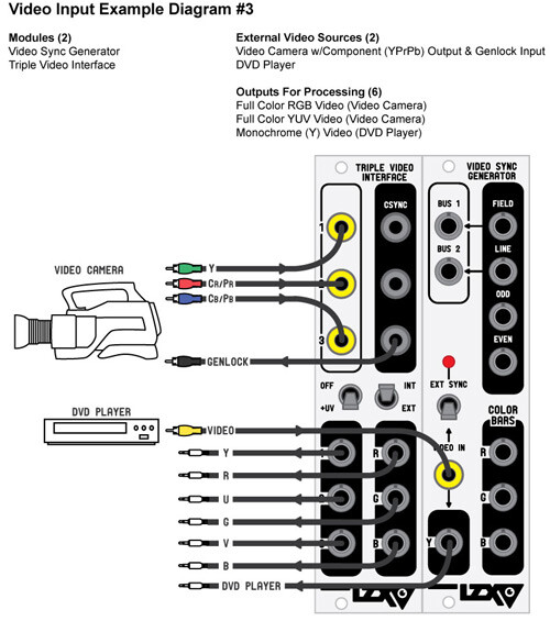
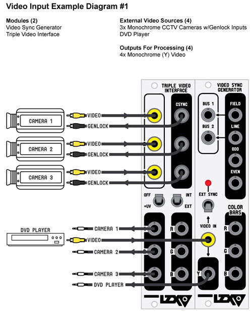
I dug up some old diagrams of our Visionary series “Triple Video Interface” module – which is pretty much what you are asking for in the OP. These diagrams show two ways to use it: one with a component video source, and one with three monochrome cameras.
We could bring this back – but the thing that frustrated everyone is that using it requires that it’s either the only external source (genlocking the system to that source) or that your sources all have genlock capabilities natively (nothing modern does except for high end broadcast cams, so we’d be selling a product that only supports a treasure hunt for vintage gear.) So it seemed to just lead to user frustration or disappointment in the end – when users found out it was not a path to getting multiple simultaneous video feeds into the system.
So this would necessarily have to go in an implicitly “Legacy / Specialty Interfaces” category of modules, since how it’s used is dependent on special gear and sync flow puzzles as illustrated.
TBC2 on the other hand is exactly what the user community asked for when we asked what was needed: a dual channel interface, “anything to LZX, always works, some good effects and media features.” So if my bringing it up is repetitive, it’s for the folks searching for this topic in the future, and the likely best answer for them.
#34 — dryodryo · 2021-10-22
No worries Lars, I didn’t feel like you reacted harshly.
I get what you’re saying about how most users just want to get signals in without dealing with genlock. TBC2 meets or exceeds the needs of the vast majority of users.
For my part, I am coming from experience with both legacy systems (IP, EAB etc) and with pro video. In both cases, genlock to house sync is assumed.
The Triple Video Interface might not be the best solution to latency free input. It seems a tad baroque, and I can see why users might be frustrated or disappointed with it.
What I would love to see is a dead simple, dumb, single channel component video decoder with genlock input. I simply want to convert YUV or RGB broadcast video to the LZX standard. VGA input would also be great, but that is less important.
Regarding staying in the analog domain for musical synchronicity, that is not possible unless someone builds or modifies some analog control gear to work with LZX. There is no analog musical keyboard available. I am stuck with MIDI. And a big part of my anticipated workflow is sequencing. Yes, I want to perform live into the video system, but I also want to record and edit that performance in the PC. So you see why I’m so concerned about latency in the video rig, because I’ve already got a potentially problematic level of latency in the digital audio domain.
Thanks!
#35 — creatorlars · 2021-10-22
dryodryo wrote:
What I would love to see is a dead simple, dumb, single channel component video decoder with genlock input. I simply want to convert YUV or RGB broadcast video to the LZX standard. VGA input would also be great, but that is less important.
That’s exactly what the TVI is. You mean Genlock/Sync output, correct? (The Genlock input would be on the camera.) If we put a Genlock input on it, then it is a TBC module and not an input amp (which is what you want to avoid.) An input amp by nature, is expecting a synchronous input source. I am just making sure you understand this.
If we brought it back, it would be revised to Gen3 standards to support HD/SD signals – and may receive extra features.
SVGA/XVGA/VGA standards can be received with the TBC2 module and scaled to one of the 15 different Gen3 “house timing” formats supported, but they are not native operational modes. So an input amp module would not be capable of supporting them.
If you are just talking about the VGA connector itself (as a way to receive SD/HD component video through a different interconnect) then that is possible.
So you see why I’m so concerned about latency in the video rig, because I’ve already got a potentially problematic level of latency in the digital audio domain.
So in this case, it is not minimal latency you want, it is being able to match the existing latency of your audio workflow, correct?
#36 — dryodryo · 2021-10-23
If we put a Genlock input on it, then it is a TBC module and not an input amp (which is what you want to avoid.) An input amp by nature, is expecting a synchronous input source. I am just making sure you understand this.
Ah, I see, thank you for clearing that up. I guess the module wouldn’t need a genlock input in the use case I envision, all devices locked to house sync.
So in this case, it is not minimal latency you want, it is being able to match the existing latency of your audio workflow, correct?
Not really, I want minimal latency, especially in the recursive domain. The existing latency is something I do not like.
I gave some thought to the analog audio synthesizer issue. It’s not that CV controllers don’t exist, its that they are in the wrong voltage range. This brings back the need for a configurable voltage scaler with presets for different standards.
Which reminds me, I can’t wait to hook my Theremax up to Chromagnon. But the issue there again is the voltage, which is 0-10V linear, very oddball.
Thanks
#37 — joem · 2021-10-23
dryodryo wrote:
This brings back the need for a configurable voltage scaler with presets for different standards.
A configurable voltage scaler is just an attenuator. And if you want presets, use a sequential (or addressable) switch in front of a mixer. Run your CV through the common input to the switch, each output of the switch goes to a different input on the mixer. Then each knob on the mixer is one of your presets for a scaling factor.
Or if you’re outputting your CV from a computer (which it sounds like you might be planning to do?), just do the scaling in the computer.
#38 — jwsmithwick1 · 2021-10-23
You could probably modify a Cadet Scaler circuit to multiply by 10x to get the 0-1v LZX signals into the 0-10v range. I’m no expert, however there are many brilliant individuals on this forum who could probably figure out the component substitutions with ease. Maybe they could chime in.
To scale down to 0-1v, there are a few options available from Ommi Industries and BSO. The WMD SPO is a nice two channel scaler that I’ve used to scale 0-5v audio oscillators into the 0-1 range.
#39 — sean · 2021-10-23
No patch memory, but Visible Signals makes the Wrangler, which is a variable scaler.
#40 — dryodryo · 2021-10-23
joem wrote:
A configurable voltage scaler is just an attenuator. And if you want presets, use a sequential (or addressable) switch in front of a mixer. Run your CV through the common input to the switch, each output of the switch goes to a different input on the mixer. Then each knob on the mixer is one of your presets for a scaling factor.
Or if you’re outputting your CV from a computer (which it sounds like you might be planning to do?), just do the scaling in the computer.
Thanks for the tips. Another thing that I’m concerned with is accuracy and repeatability. Part of my vision is running signals through patches in sequential passes, building up layers that are as close to being pixel accurately registered as possible. Think Scanimate on steroids. To keep the process as error-free as possible, I want to minimize the number of potentiometers involved. Even the new LZX regime of detente knob positions with tweaker calibration makes me nervous.
As for voltage scaling in the computer, that may or may not be an option or a convenient solution. I have many unanswered questions. I’m planning on getting an Expert Sleeper ED-9 once they are available again; I can ask the designer if it’s easy to configure for different voltage standards. I don’t want to be attenuating outputs in the DAW or virtual instrument; I’m concerned that would make monitoring levels difficult or impossible.
jwsmithwick1 wrote:
To scale down to 0-1v, there are a few options available from Ommi Industries and BSO. The WMD SPO is a nice two channel scaler that I’ve used to scale 0-5v audio oscillators into the 0-1 range.
I was aware of the Visible Signals Wrangler, but again, I’m trying to avoid knobs.
I was aware of the Brown Shoes Only module. The big issue there is that some of the LZX gear is expecting a signed voltage -1 to +1, and the BSO 5:1 only outputs positive 0 to 1V. Thanks for the info about the WMD Scale Polarize Offset module. That looks good except for the potentiometer issue.
The Omii Industries Curtail module looks like it will handle signed or unsigned signals , and doesn’t have any pots to worry about. So that’s a good option as long as there’s no need to do any DC offset. But I can easily envision a situation in which that would be needed. E.g. 0 to -10V needs to be converted to -1 to +1 V.
This is why I am saying I want a configurable voltage scaler. There is a plethora of standards out there. Or should I say there really is no standard out there. When dealing with analog synths from the 70’s and 80’s it’s pretty much all 0 to 10 V, 1V/octave for pitch. But when you get to Eurorack audio, it’s all over the map.
So ideally I would like to see a voltage scaler with no knobs, but instead some switches or even a menu system. It should be capable of attenuation, amplification, DC offset, and inversion. That way it could convert to or from LZX voltage standards, or even among various random Eurorack modules.
The voltages it should support would be:
-10 to +10
0 to +10
-5 to +5
0 to +5
-1 to +1
0 to 1
#41 — creatorlars · 2021-10-23
dryodryo wrote:
Part of my vision is running signals through patches in sequential passes, building up layers that are as close to being pixel accurately registered as possible. To keep the process as error-free as possible, I want to minimize the number of potentiometers involved.
You want a USB-to-CV interface that can be calibrated on the software end to output a 0 to 1.0V scale. Check out the products by Expert Sleepers.
#42 — creatorlars · 2021-10-23
dryodryo wrote:
So ideally I would like to see a voltage scaler with no knobs,
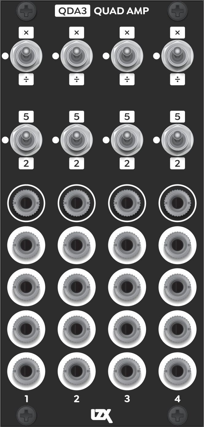
This is what we are planning presently. It is a 4-channel voltage attenuator/amplifier with 4x buffered outputs per channel (so you can guarantee identical impedance.) This covers the standards you mentioned. There is no unipolar to bipolar conversion and back – but that’s not usually an issue in context. +/-1V signals and double gain +/-2V are part of the LZX standard too, as of Gen3.
Analog processing tolerances will sit around 1% to 2% of nominal (we use 1% resistors throughout all the builds.) I’m sure the tolerances on the Scanimate were much worse. But repeatability? You can get that. Just have attenuverters fully clockwise or counterclockwise and use a precision USB-to-CV interface as mentioned above – and you can micro-tune your voltage in software.
Another mention is that the ESG3 module has trimmer adjustable RGB Gain + Offset levels. So with that as output encoder, you can always calibrate the color balance across multiple outputs.
#43 — dryodryo · 2021-10-23
creatorlars wrote:
Check out the products by Expert Sleepers.
Thanks, I was planning on getting an ES-9 when it’s available again… wasn’t sure how configurable the outputs are, but it sounds like it will do what I need.
creatorlars wrote:
This is what we are planning presently. It is a 4-channel voltage attenuator/amplifier with 4x buffered outputs per channel (so you can guarantee identical impedance.) This covers the standards you mentioned. There is no unipolar to bipolar conversion and back – but that’s not usually an issue in context. +/-1V signals and double gain +/-2V are part of the LZX standard too, as of Gen3.
That looks great! So to convert 10V to 1V I would need to use two channels of the Quad Amp?
+/- 2V is news to me… what is up with that? Why? Where?
creatorlars wrote:
But repeatability? You can get that. Just have attenuverters fully clockwise or counterclockwise and use a precision USB-to-CV interface as mentioned above – and you can micro-tune your voltage in software.
Fantastic! All great news!!!
#44 — creatorlars · 2021-10-23
dryodryo wrote:
+/- 2V is news to me… what is up with that? Why? Where?
This would be in cases where you want to overdrive the parameter range. Think of it like +/-200% as opposed to +/-100% or 0 to 100%. For example, the SMX3’s attenuverters go to +/-200% scale so that you can convert from YUV to RGB and back again. YUV to RGB requires some gain beyond 1.0X to reach full scale.
It’s also the available minimum headroom on any module (meaning you can always patch up to +/-2V to an input without clipping before attenuation.) So in other words, if you can get your external voltage down to within +/-2V, you can patch it around the system without losing any part of the signal. The FKG3’s RGB inputs for example – they could switch between +/-2Vpp signals on the foreground and background if desired.
Another example is to think of say a vector based parameter like “width”. We may want the range to be 0% to 200%, or “nil to 2X”. For math reasons with four quadrant multiplier circuits we may want the following to be true:
1.0V * 1.0V = 1.0V (unity gain)
2.0V * 2.0V = 4.0V (clipped/amped behavior)
#45 — creatorlars · 2021-10-23
dryodryo wrote:
So to convert 10V to 1V I would need to use two channels of the Quad Amp?
Yep! We haven’t committed entirely to this layout yet. Another option would be swapping a channel or two in exchange for rotary switches that allow more settings and offsets. But if you can gang channels for other ratios… are we just removing channels for no reason? “Channels per HP” is the currency to consider. We want to see what users think after playing with the first set of modules before making any final decisions. This seems like a balanced solution for both signal distribution and conversion that covers most user needs to myself, at the moment. But I generally work exclusively within the LZX ecosystem personally, so I may not be the best arbiter of use cases here.
#46 — creatorlars · 2021-10-23
Here’s another interesting case for bipolar signals. Since ESG3 lets you set a “default RGB gain/offset” with trimmers, you have the ability to tune your system to alternate ranges and standards in a new way.
For example, for 0V to 1V = RGB type behavior, you would trim the offsets to 0V (black) and the gains to 1X (which sets 1V = White).
This method preserves this assumption: WHITE - WHITE = BLACK and BLACK + WHITE = GRAY.
This is Metallica style (fade to black.)
For +/-1V = RGB type behavior, you could trim the offsets to +0.5V (50% gray) and the gains to 0.5X (which sets -1V = black and +1V = white.)
This method preserves this assumption: WHITE - WHITE = GRAY and BLACK - BLACK = GRAY.
This is Visage style (fade to gray.)
Many vintage video synths (for example the Sandin IP and most of Dave Jones’ instruments) used bipolar signals and were more Visage style.
Since at LZX we mostly listen to 80’s metal, we defaulted to Metallica style in the early days. Also, we wanted to preserve the type of RGB math relationship used in compositing and RGB graphics – where RGB is an unsigned integer from 0 to 255 or 0 to 1023, etc.
While Metallica style is more accurate / useful if you are doing math with colors – there are benefits to Visage style. If you mix bipolar signals in a summing bus for example, each will end up increasing/decreasing contrast relative to each other while keeping median brightness consistent at gray instead of additively boosting “exposure” with each additional source in the mix. I’m certain in a future blending/compositing module, we will have the two approaches as different modes.
Of course on ESG3 you can get to both places with adjusting the control knobs directly – it’s just being able to trim those null spots to different places that is a new functionality.
#47 — dryodryo · 2021-10-24
creatorlars wrote:
Another option would be swapping a channel or two in exchange for rotary switches that allow more settings and offsets.
On that Quad Amp mockup, it looks like each channel has one input and four outputs. I would be quite happy with more channels or more controls, I would just use a mult module or stacking cables if I needed more outputs. I also would prefer not to gang channels together, that cuts the number of signals in half.
So for me at least, I’d prefer four channels, each with:
-
one input
-
one output
-
two position toggle switch for multiply or divide
(no need for neutral setting if no mult function)
- rotary switch for multiplier/divider value, with at least these options: 2, 5, 8, 10
(apparently some manufacturers, e.g. Noise Engineering, use 8V)
- three position toggle switch for DC restore: bipolar to unipolar, neutral, unipolar to bipolar
Thanks
#48 — dryodryo · 2021-10-24
I like your Metallica / Visage analogy.
I can tell you that the Sandin IP was a real pain to work with in that regard. I absolutely hated the bipolar scheme. HATED IT
#49 — creatorlars · 2021-10-24
dryodryo wrote:
I would just use a mult module or stacking cables if I needed more outputs.
The intention is that this is both the system’s quad active mult and it’s quad amplifier/attenuator (with presets). Think of it as straddling both functions (which are essential, core functionality for a modular system). We found this worked well in patching context on our Bridge module – usually if you’re level translating an external signal, you want a mult at the same place (to distribute through your patch.) Also, many cases where you are using an active mult – preset gain modes come in quite handy (like overdriving a video source to create a distributed soft key.)
The 2-in-1 nature here serves another purpose: a voltage scaler may not be used in all patches, but a dedicated mult is almost always going to be in use. So this is a currency in our design guidelines – we want every HP worth of module to be useful in as many different patches as possible, even when they play different roles. It’s a big ask, to pay a lot for a module with some preset voltage scalers on it, so we try to overlap things in a way where the module can pay it’s rent in multiple ways. That’s my thought process in any case.
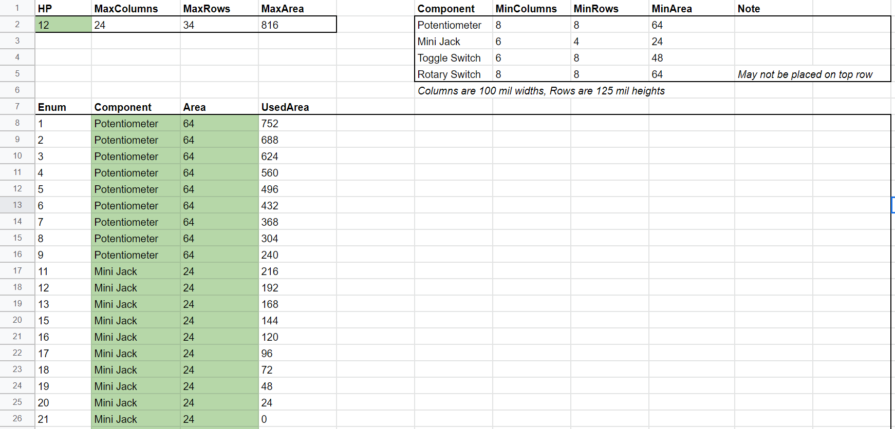
Unless arranged in rows instead of columns, the inclusion of rotary switches would require that this be a three channel (instead of four) module. You can see the formula I’ve developed for Gen3 ergonomics here so you can see the constraints more specifically (this example shows SMX3 – 9 knobs, 12 jacks):
two position toggle switch for multiply or divide (no need for neutral setting if no mult function)
Agreed on this point if we excluded a mult – however it’s worth pointing out that a 3-position toggle is essentially “free.” That is, no extra panel space and negligible extra parts cost to go 2 instead of 3. Some controls are of course, binary by their nature and a third position could be confusing.
A three position “bipolar to unipolar / bypass / unipolar to bipolar” toggle is something I had on an earlier mockup. I think that’s a good idea, especially if we drop some mults.
Another alternative to mult outs are complementary outs (positive and negative.) For example, we could drop 2 outs in favor of this. This would be a similar layout then, to DSG3, if combined with a polarity mode (12x toggles, 12x jacks)
Dropping the mult outputs – adding the complementary outputs – we could have a third range setting on the amp level. For example, 2X, 5X and 10X. This could work, but then we need a separate module as the go-to active mult (not really an issue, but if you are trying to make a small system it makes it more difficult, if you need both functions.)
These are just designer musings – not necessarily a defense of the existing configuration. This is actually a great case where soliciting user feedback before we commit to a design is a good idea.
#50 — dryodryo · 2021-10-24
creatorlars wrote:
Another alternative to mult outs are complementary outs (positive and negative.) For example, we could drop 2 outs in favor of this. This would be a similar layout then, to DSG3, if combined with a polarity mode (12x toggles, 12x jacks)
Love it. That would be genius.
#51 — creatorlars · 2021-10-24
I guess so long as we’re brainstorming… one thought is that the gain levels (2X, 5X, etc) are trimmable by the user, and are instead more of “Setting 1” and “Setting 2”. That way you can null out any tolerance stackup and they can be recalibrated to any desired voltage standards. So they could be 1.8X and 8X instead, and also you could calibrate channels differently. This would be starting to add the kind of value that might justify a dedicated module (without mults.)
#52 — dryodryo · 2021-10-24
creatorlars wrote:
one thought is that the gain levels (2X, 5X, etc) are trimmable by the user, and are instead more of “Setting 1” and “Setting 2”
I guess you could add tiny tweaker trim pots. Calibration would require a scope or multimeter, though… not sure how popular that would be.
#53 — creatorlars · 2021-10-24
dryodryo wrote:
I guess you could add tiny tweaker trim pots. Calibration would require a scope or multimeter, though… not sure how popular that would be.
Well I reckon they’d be pre-trimmed to the 2X and 5X defaults, and likely never touched (so it’s more of an advanced user recalibration thing, accessible from the front but under the panel – like the XYZ trimmers on Chromagnon and the RGB trimmers on ESG3.)
If you have very precise scaling needs – or a scaling need for something uncommon, legacy or odd – like an 8V envelope or a +/-10Vpp LFO, or a vintage Buchla – or you need incredibly tight results (like you need that V/Oct keyboard to open and close a key precisely in 5ths, etc) – it could come in quite handy and prevent dead ends or redundancy in the system design.
And I don’t care about popularity so much – Gen3 can have some modules that are less popular, we’ve designed the supply chain where a module that may be “academically important” can still have a place even if it’s not a hot seller. Biggest things for me are functional value and usability, from folks exactly like yourself – artists allocating their hard earned budgets to tools they need access to.
So given that voltage scaling is a common need, whatever the first Gen3 module in this category is, it needs to cover the widest range of use cases for artists out there.
#55 — rempesm · 2021-10-24
DesertMuseum wrote:
Even better-control voltage inputs - which so far seem to be missing from the Gen 3 modules we have seen so far.
They’re all control voltage inputs! If you need to vary the depth of modulation on any input, patch them into a VCA or crossfader beforehand or sum your input signal with another modulating signal to bias a parameter up/down.
#58 — rempesm · 2021-10-24
That makes sense. Adding VCAs (or ideally 4Q multipliers!) to every input can ease spontaneity in patching but they will necessarily add to HP and overall cost per module. “You can never have enough VCAs” is probably even more of a truism in video synthesis since they often determine where your signals appear, allowing for denser compositing approaches.
DesertMuseum wrote:
voltage control over manual switches
This can be quite a cool effect if you use video rate signals to alter where on the screen a module is switched into one mode or another (kind of the inspiration for SHUTTER, I’d say). I think that could get really darn confusing with a fixed voltage scaler, though. The module above seems very utilitarian in nature.
DesertMuseum wrote:
Maybe its just a patching style thing?
Oh for sure. There’s no ‘right’ way to patch these instruments up. I just happen to mix and mingle most of my signals with intermediary mixers and VCAs.
#60 — creatorlars · 2021-10-24
Maybe its just a patching style thing?
Not really – it’s more of a functional identity and design-your-own-workflow thing. Think of it in terms of modality. The switches are setting the module – or in this case channel’s – mode or state. If you have four identical channels, you can switch between their outputs to create whatever modulation scheme you can dream up. If we’re talking “how much can I do per HP” then this is wildly more powerful and flexible than giving each toggle switch a CV input.
This is not new – for example, you can compare DSG3 to Visual Cortex’s Ramp Generator section pretty directly.
The modulation happens on the outside of that – for example, DSG3 has two identical shape generators. Patch one to FKG3 background, and the other to FKG3 foreground, and what you’ve set up is a voltage controlled fade between two different groups of settings. Now in 24HP you have a “programmable RGB shape morph”, creating a kind of super module where you can design whatever kind of CV modulation you want. This becomes quite deep quite quickly. You want to control a transition from star to circle? You can do that fast and easy, even after you’ve set up your patch, just by flipping the switches on either side of the transition.
If we were to put CV controls on the DSG3 (and sacrifice one of the channels as a result) you end up with a shape generator with voltage control – but it’s not capable of nearly the same range of functionality as the DSG3 + FKG3 combination would be.
So it’s not that we’ve dropped CV inputs (they are there! on FKG3, and DWO3), it’s that we’ve introduced the idea of more multimodal modules.
With Expedition series there is a lot redundancy with certain CV inputs. For example, Marble Index’s CV inputs + attenuverters are handy for more abstract use, but redundant in the case where you’re patching in a key (in this case, the key generator itself would have already set the control range.) This makes it more difficult to use the module for it’s intended purpose.
So to sum all this up, it’s all about ratios: You’re the one in control of how much CV modulation your system has! If you want lots of discrete transitions, go heavy on FKG3s and lighter on the other modules. If you want more programmable settings, go lighter on the keyers and switchers and heavier on modules with programmable modes.
Consider the toggle switches less as “parameters to modulate” and more “several modules in one, which one do I pick for this patch?”
#62 — creatorlars · 2021-10-24
Thanks for reading the ramble! This has all been such a journey. It would be easy to design a modular video synthesizer modeled only off of traditional modular synthesizers, replacing the typical functions for faster equivalents – it would also be easy to model it only off of existing video equipment and node based compositing, but with an altered form factor – but it’s always been my view that these are all only component views of a larger vision of what an instrument like this could be.
To discover what that is, it takes iteration, feedback from users, and a willingness to start over in phases. It’s a kind of freedom to have launched something that was purely experimental from the beginning days – in terms of “market feasibility” or from the business standpoint, it was never a “good” idea – and to me, that has always been a boon. As we’ve grown and the community has grown, we risk losing that freedom and becoming entrenched – the growing pains become stronger – it’s what we’ve been dealing with the past few years – not just with the designs, but also the scale of manufacturing. I do think the Gen3 modules are going to be the defining version of LZX modular, the encapsulation of our approach and experiences – one that was created not just by us, but also all of you, by supporting and using these modules through their earlier iterations. In the same way Cadet was an attempt to catalogue and codify the electronic function blocks of Visionary series, this is an attempt to codify and catalogue all the workflow steps that have been envisioned and developed along the way – including the more emergent usage and needs of the user community.
All of this is to say – if you’re initially skeptical about these new modules, that’s okay – but give us a shot to show you how it’s all intended to fit together. In the end I think you’ll find that it’s not just our ideas in here, but everyone who has offered feedback along the way, even if it might seem counter-intuitive at first.
#64 — dryodryo · 2021-10-24
As I’ve said before, Gen3 looks like LZX has reached full maturity. I agree that this is the defining version of LZX modular. Hits the sweet spot in every way. And it’s very reassuring to hear that with standardized design manufacturing you’ll be able to release more specialized “niche” products.
With the jump to HD, I think the customer base is going to increase. That should lead to more predictable supply/demand ratios. One of the things that has kept me from entering this field is the volatility of availability. Stuff is only manufactured for a short window of time, and if you snooze, you lose. For those on a budget, this often means they miss out entirely, because they don’t have the cash or credit during that manufacturing window. Then in order to buy anything on the used market, one must be CONSTANTLY checking the Facebook groups. The window of availability there is minutes to hours. This is a terrible situation for anyone who doesn’t have a lot of cash on hand to buy stuff the month it’s released. So with the move to Gen3 I am hoping this issue is resolved and the tools get out to everyone who wants them.
THANKS