Animating and modulating colours
Category: Unknown · Tags: — · Posts: 83
#1 — Gavin · 2022-01-10
There was a thread about this on the fb group but I had more thoughts and figured this is a better repository for patch ideas.
For animating colours:
Use a quadrature oscillator (Bajaoscillator) and mix it in with the RGB source, one phase for each red green blue. You can mix this with passage, bso crossfade, or a matrix mixer.
If you have a feedbackpath with delay (MemPal, mixer, etc), send your color info through wave folders (Arch, Staircase, or audio wave folders) for that nice deterministic chaotic behavior. If you have mapper and a S/H module, you can apply this on Hue, or you can do it on each color channel.
I have also sent color video feedback through Color Chords and created periodic color changes that way.
#2 — Gavin · 2022-01-10
If you look up Phil’s Castle lesson 1 in this forum, you can combine these with a posterise effect, which steps your image’s luma into bands, which will nicely limit you to 8 colours.
I have been thinking about how to achieve an 8/16bit style ‘colour cycling’ effect - explained in a lovely way here: The lost art of color cycling - Animating with color - YouTube
The nearest I can get would be to first apply the above posterise effect, and then to use Bajaoscillator into RGB to move colours, but to first pass it through a Sample and Hold (with a slew option to soften things a bit) to get less linear movements through your Hue or RGB. I suppose also if you used something like a WMD PDO, you could have much finer control over the colour cycling palette because you can also control the degree of phase between its outputs.
#3 — Rik_bS · 2022-01-10
This will be a fun topic to explore, I really enjoyed that Colour Cycling video when it was shared elsewhere.
Worth noting the Bajascillator outputs are 60 degrees apart which works well for RGB - 0, 60 and 120 whereas most eurorack quadrature oscillators are 90 degrees apart.
I’ve been meaning to play with the Quadraturia mode on my Ornament & Crime module, which offers wavetable LFO (based on the Mutable Frames easter egg mode) with adjustable output & offset level, phase and waveform.
I’m pretty confident it can hit 0-1V at 60 degrees with the right settings

Will report back with my findings!
#4 — rempesm · 2022-01-10
Rik_bS wrote:
I’m pretty confident it can hit 0-1V at 60 degrees with the right settings
>>>> Will report back with my findings!
Courtesy of @Genlok figuring this out:
The proper settings for 0-1V coming out of Ornament & Crime’s “Quadraturia” mode is:>>>> Output range: 24>>>> Offset: 95>>>> (Offset: 82 for -.5/+.5)
#5 — Rik_bS · 2022-01-11
that is amazing, thanks for sharing!
saves me some time, can just fire up the 'scope and see what setting it takes to get 60 degree phase separation (guessing 84 or 85)
for anyone that’s unfamiliar with it, I’d suggest trying to get the 8HP version - “uO_c” - in your rack, it’s worth it for Quadraturia alone and everything else (a myriad of functions) is a bonus. Especially given you have ability to scale the LFO outputs without external modules.
#6 — Gavin · 2022-01-11
Okay, so my Bajaoscillator arrived today. Here are my beginners’ problems which might help anyone else:
I have:
VC diamond ramp > doorway for sizing and hard/soft edges > into all 3 passage thru > VC RGB in
Bajaoscillator > all 3 passage in
But I’m running into an issue with my patching logic. The bajaoscillator adds amplitude to each RGB channel, which is basically 3 sets of brightness changing, so I am running into this issue:
If the shape doesn’t have a hard edge (eg. a diamond ramp via castles), then the shape grows and shrinks with the amplitude, along its gradient, and its pretty impossible to balance the RGB amplitudes so that you keep the shape and its gradient stable, but change the colour of it. I’m guessing having a castle shape or soft edge that changes colour needs some other approach?
The only thing I can think of is just to go through Mapper and animate the hue, but maybe there are better ways.
#7 — creatorlars · 2022-01-12
Yes, Mapper is what you want to modulate the chrominance/hue directly, and without changing the luma/brightness value. Any type of direct RGB manipulation will also involve shifts of and cross modulation of the image’s brightness. Neither is really a superior approach (that is, 3-phase displacement vs polar-to-cartesian shaping) they are just different techniques. Sometimes the RGB cycling approach can lead to different palettes and the shifts in brightness make the image more dynamic as a result.
#8 — rempesm · 2022-01-12
Here’s one approach to try:
Sum each color channel with its own step sequencer clocked by a divided down frame rate output.
Let’s say we are using 3 Befaco Muxlicers or any other step sequencer matched up with R, G, & B out of any full color image you’re working with in the system. In this patch it’s an external camera feed in through CTBC but it can be whatever:
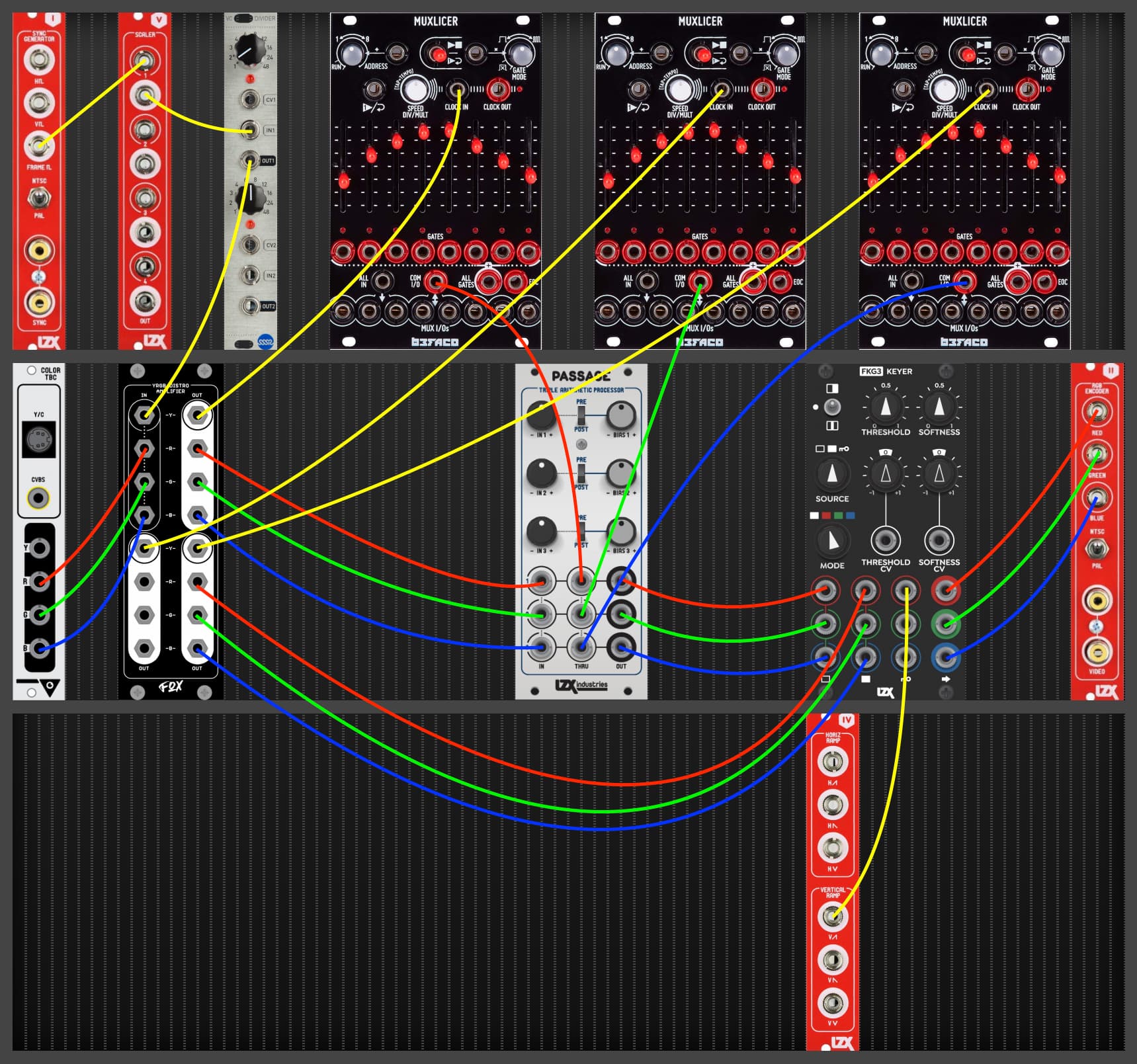
You could flip around the inputs into Passage (IN<>Thru) or add another Passage in line so you can invert/bias the sequencers’ outputs to allow for subtraction from the RGB channels coming from your source.
The key input on FKG-3 could be a variety of things (it’s just a H ramp in the example) and is the way to not just have the entire screen tick through the same sequenced palette cycle. I would probably start by putting the Y from CTBC into the Key input so I could constrain the palette cycling to the brightest areas of the external camera input.
EDIT: You could also just use one sequencer and put its output into a Passage to get three simultaneous stepped voltages sitting at different, repeatable amplitudes.
#9 — creatorlars · 2022-01-12
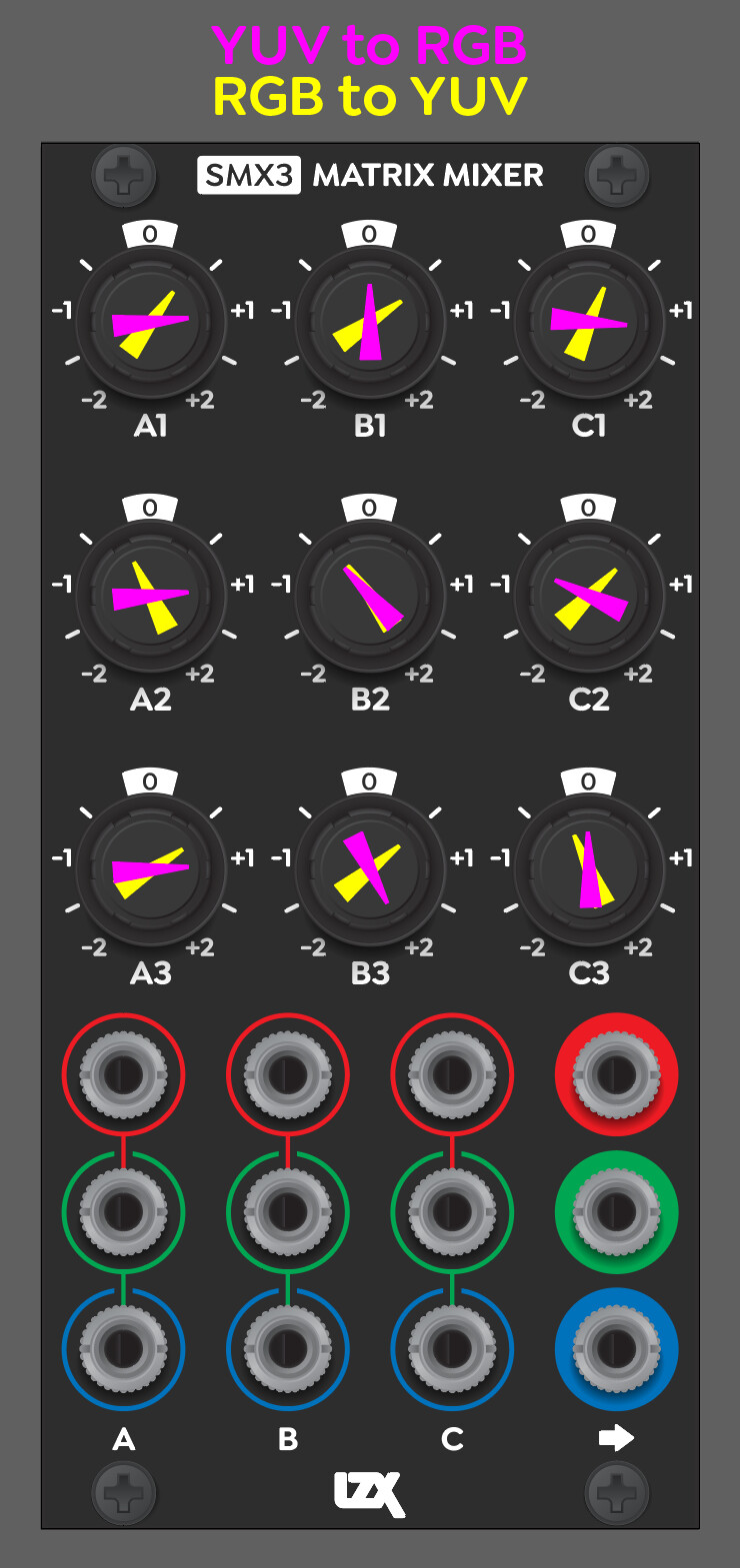
Another idea to try is to use a Quadrature VCO as a UV(Chroma) source and then converting UV + a static Y value using a YUV to RGB matrix. (This is similar to what’s behind the scenes, at Mapper’s output stage.) This will give you continuous hue cycling.
Here are some settings for YUV to RGB and RGB to YUV on the SMX3 (but any 3X3 matrix can probably get you close.)
#10 — dryodryo · 2022-01-17
YES! Thank you Lars for that illustration of converting color spaces!
Which brings up the question, is there a plan for a Gen3 HSL workflow? I would love to easily convert RGB to HSL and vice versa.
The ability to adjust color separately from luminance is kind of critical, and as you pointed out, it’s impossible to do that in a pure RGB signal path.
Something like Mapper but really just a conversion module. Bidirectional, two modules in one. Don’t need parameter adjustment pots, just convert color modes.
#11 — creatorlars · 2022-01-17
dryodryo wrote:
is there a plan for a Gen3 HSL workflow?
Yes. “HSL Amp” is a no brainer for core gen3 modules. This would be like Mapper but with RGB input as well as output. I think this is a good example of a function that should be wholly represented in a single module – RGB in, RGB out, HSL controls – (but LZX hasn’t done so yet.) FKG3 was like this, too (integrated keyer/key generator).
#12 — dryodryo · 2022-01-17
Actually what I was asking for is a conversion module, not an HSL proc amp. I want to take an RGB signal from TBC2 or whatever, convert it to HSL voltages. Send that to other modules, e.g. function generator, summing mixer, etc. Take that back into the conversion module, convert it back to RGB for encoding.
Thanks.
#13 — creatorlars · 2022-01-17
dryodryo wrote:
Actually what I was asking for is a conversion module, not an HSL proc amp. I want to take an RGB signal from TBC2 or whatever, convert it to HSL voltages. Send that to other modules, e.g. function generator, summing mixer, etc. Take that back into the conversion module, convert it back to RGB for encoding.
You can do that with 2x SMX3 using the YUV/RGB settings shown above. The Hue/Saturation are encoded as UV quadrature, so any of the system’s existing (or future) 2D processors will work to modify things like Hue (using a rotator function) or Saturation (using a dual VCA/amp). In other words Hue – when patched as a signal on patch cables – is a 2D plane represented by the UV voltages, and you process it using 2D functions rather than singular VCAs, etc.
An HSL amp is effectively a 4-in-1 module: YUV-to-RGB circuit, Polar-To-Cartesian Waveshaper (Hue to UV rotation processor), Dual Amp (UV amplifier), and RGB-to-YUV circuit encapsulated in a 12HP function block. We can include the IO of the YUV-to-RGB amp and the RGB-to-YUV amp on separate outputs so you could use it as a dual converter as well! So maybe what I mean is less “HSL amp” and more “HSL/YUV/RGB toolkit/converter/processor”?
That doesn’t mean a YUV/RGB cross converter wouldn’t be a nice utility function for a single module though. The way the cost of the parts and space required for the circuitry works out, it’s to everyone’s advantage (aka Max Feature to Cost Ratio) if we combine things in these 12HP blocks.
I also have to think about the cost of certain functions when split across different modules. For example if all modules are $399, and it takes two separate modules to accomplish a hue transformation, then the hue transformation feature costs the user $798. Whereas I think maybe the best place to start is to make sure that function (which is a core function I think) can be done in a single module.
I could see some large panel modules of patch-only function blocks including YUV/RGB converters though, a “Patch Programmable Color Lab” kind of thing.
#14 — dryodryo · 2022-01-17
Thanks for that, I always learn so much from you Lars.
The thing is, I want to be able to process hue and saturation separately, with each parameter being its own one-dimensional space. I want to do that processing externally to the conversion module, in other modules. And most importantly, I need it to be intuitive. I guess I could theoretically process an R-Y / B-Y pair to get the same results, but that is not at all how my graphic artist brain works. Yeah, I can read a vectorscope, but that doesn’t mean I know how to adjust R-Y / B-Y values to dial in a particular color. I mean, it’s really not at all intuitive; changing either value will change both the hue and the saturation. So we’re back at a similar issue that we have with pure RGB workflows: we can’t just tweak hue or saturation without affecting the other. They only work as a pair. You can build in some smart functionality to your other modules, creating a hue and saturation “front end interface” to adjust the R-Y / B-Y values under the hood. But that doesn’t help the situation in which, e.g. I want to send just the hue through a function generator and leave the saturation alone.
I totally get your mission to consistently pack $400 worth of functionality into 12HP. It makes a lot of sense, in terms of modular circuit design, front end interface design, and marketing. So a color conversion module could have proc amp controls, that’s fine, but the most important thing for me is to get a proper RGB → HSL and HSL → RGB conversion. Like a bidirectional Mapper. I really don’t care about R-Y / B-Y, that has extremely low utility value for me.
Thanks!
#15 — creatorlars · 2022-01-17
dryodryo wrote:
Yeah, I can read a vectorscope, but that doesn’t mean I know how to adjust R-Y / B-Y values to dial in a particular color. I mean, it’s really not at all intuitive; changing either value will change both the hue and the saturation. So we’re back at a similar issue that we have with pure RGB workflows: we can’t just tweak hue or saturation without affecting the other.
That’s why with analogue you need to process your chrominance (UV, etc) with a quadrature function generator (like the Polar to Cartesian function and Dual VCA in Mapper) rather than a mono function generator. Ultimately what I am describing as HSL amp is exactly what you’re asking for, let me try to explain.
I guess I could theoretically process an R-Y / B-Y pair to get the same results, but that is not at all how my graphic artist brain works.
Part of this is our understanding of graphics vs analogue/video signal paths and functions, and our tendency to not think of “parameter inputs” as also “potentially image rate transformations.” For example, you can’t patch the luma channel of a separate file directly to the “Hue” parameter in Photoshop and expect an image rate colorizer to appear. You can get that transform through a series of steps. But in an LZX system, the HSL inputs on an “HSL amp” are by default an “HSL to RGB converter with adjustment controls.”
So if you want to curve, fold, manipulate the “Hue” of your image in complex ways? That’s all in what you’re patching to the “Hue” input of the “HSL amp.” And that could be anything (a ramp or waveform, another image, the same image’s luma solarized 8 times over, etc.)
For HSL “output” that’s best represented as UV or Sin/Cos quadrature for exactly the reasons you mentioned – we want to process Hue/Saturation using modules designed to operate on a 2D plane rather than as mono functions. Hue does not really exist without Saturation (there has to be a constant value at least, to calculate the chrominance of one or the other.) Whereas U and V do exist, even without each other’s presence.
To sum it up, in patchable analogue, it’s best to think of Hue and Saturation not as a “signal type” or a value – something you patch on a cable – but as parameters describing a transformation of the UV colorspace. So whether we hide those high parts count transformations (Polar to Cartesian, Dual VCA, etc) behind the panel or give them frontpanel controls, they exist regardless. In the case of standalone HSL to RGB to HSL, etc it makes the most sense to “patch it out” and give the user access to those expensive functions directly. If modulating/generating Hue as it’s own channel is the goal, you just go into the Hue input with your alternative “hue source.”
Of course, there is more than one way to solve these problems with circuits. For me the real practical thing is “an HSL converter costs the same amount of big circuits as an HSL generator/converter/processor.” So from what I’d have to charge for the module, the HSL instrumentation frontend just fills out panel space that would otherwise be entirely blank. No way to make the whole circuit “smaller” without compromising other parts of the design standard (bloating power consumption, bloating panel space, etc, deeper mounting depth, etc).
#16 — Gavin · 2022-01-17
If I imagine it, the simple ‘artist’ control for this prospective module I’d enjoy would just be some CV control inputs post RGB conversion, and then you could patch in a joystick with eg. X into Hue/U and Y into Saturation/V? And then converted to RGB on its way out…
#17 — creatorlars · 2022-01-17
A joystick is a great example of how chroma/UV is a 2D plane. If you take XY as UV, then patch those to a YUV to RGB matrix function (like posted above), your joystick will now work like a Chroma value selector without adjusting luminance (Y) which can be a static value or have a different source. Your joystick’s output is “XY/UV”, but you can control Hue/Saturation based on how far you move the joystick from center (Saturation) and angle of rotation (Hue.)
#19 — creatorlars · 2022-01-17
I may be wrong, but I think @dryodryo is just trying to exhaust the applications imagined for all of this from their background as a teacher and instructional designer in digital graphics. I don’t mind that, I like the challenge of explaining “how this fits into that” and the context for design decisions. This particular intersection between analogue systems and graphics is incredibly interesting to me, because it’s part of the goal with all this, for the analogue system to be the counterpoint/complement of (and not the equivalent of/replacement for) existing graphics tools.
So, case in point, hue transformation – one simple slider and floating point value in software! And HSL to RGB is usually a very low level presumption in any graphics engines out there. We’re used to this being an effortless operation. It makes sense that being able to separate hue and saturation and process them as unique values should be possible, since that’s exactly what you’d do in a graphics environment, to avoid modulating saturation and luminance and address hue directly.
In analogue though, it’s a Big Circuit, in parts cost, complexity, footprint. Hue and Saturation aren’t signals, they are complex analogue computing functions/transformations – If you’re gonna have it in there, you want to give the user full control over it’s inner workings. You want the macro version, with all the details that make the real time analogue circuit powerful in ways the digital graphics system is not. There’s a lot more that an HSL circuit can do in a freeform, wide bandwidth environment than just color conversion! So this informs how we strategize the instrument. In the end I hope that by embracing the form of the circuitry itself, we avoid abstracting away the details that make the analogue workflow unique.
#20 — creatorlars · 2022-01-17
To make some definitions:
RGB Colorspace Signals
- Red
- Green
- Blue
YUV Colorspace Signals
- Luma (Y)
- Blue - Luma (U, Pb)
- Red - Luma (V, Pr)
Colorspace Matrix Conversions
- YUV to RGB
- RGB to YUV
RGB Transformations (these are 1D functions)
- Red Contrast
- Red Brightness
- Green Contrast
- Green Brightness
- Blue Contrast
- Blue Brightness
Y/Luma Transformations (these are 1D functions)
- Contrast
- Brightness
UV/Chroma Transformations (these are 2D functions)
- Hue
- Saturation
And, personal perspective:
Advantages to RGB colorspace: This is closest to how light works. This is how human eyeballs work. It’s the most natural way to mix two images and, as signals, carry the most relevant information about the color. It’s how you learn about color in the fields of physics or optics.
Advantages to YUV colorspace: This is closest to how artists think, especially if we’re using Hue and Saturation based transformations of the space (it’s modeling of the concept of a color wheel – something that does not exist in nature). This is how you are taught color balance, paint mixing, value ranges and contrast, etc in a painting or design class.
#22 — creatorlars · 2022-01-18
7pip wrote:
How do you avoid creating an ‘Ivory Tower’ for the theoretical without examining something like a case study that puts the theory in context?
I agree. When it comes to the modules, what goes on the panel, how the user interacts with it, practical context and case studies have to be part of the evolution of the instrument.
But that’s systems/instrument design. When it comes to functions themselves, we are just talking about math. We can talk about those equations and how they can be implemented with an analogue circuit, in isolation from their place on a frontpanel and in someone’s rack. For example, Hue to RGB isn’t theoretical – it’s an equation.
“How to implement hue controls in an analogue video system” is a different question. And the right design solution is going to be one that balances all the concerns at play: cost, performance, footprint, usability, etc. With Gen3 I’m being very picky about how things are implemented – redundant approaches should be based in how you patch, rather than how many modules you need to buy. I think a single HSL Amp module, for example, can cover all the needs discussed in this thread in the 12HP form factor. Mapper but with RGB to YUV on the frontend and the addition of a rotator on the backend.
In order to justify HSL functions beyond that module, we’d need to have some use cases which weren’t already patchable by that module. I can’t think of any, but if we can find some – that’s what conversations like this are all about!
#23 — dryodryo · 2022-01-18
OK Lars, can you explain why I shouldn’t think of HSL as a signal…?
Is it is simply easier to create a module that modulates some incoming signal using HSL math? Or, to put it another way, is it is harder to convert an RGB triplet signal to an HSL triplet that can be sent to other modules?
The signal flow has major implications for the types of patches/effects/mind blowing moments that can be made. I’m totally fine with the paradigm of “send your signal through this one box and send a complex modulation signal to mess with it”. But I would actually prefer the paradigm of “send your signal through this network of weird boxes that interact with one another in messed up ways”. Honestly I think the latter approach is more desirable because it’s more open to happy accidents.
#24 — dryodryo · 2022-01-18
Are you asking me? Thanks, here it is:
dr-yo.comhttps://www.dr-yo.com/video.htmlAbstract video art, computer animation, and electronic music by Aaron F. Ross, also known as Dr. Yo.
Link: Video Art by Aaron Ross
The video synth stuff is old, it’s from the 90’s. Scroll down to the bottom of the page.
Here’s one of my favorites, I’m planning a sequel. WARNING stroboscopic flicker / epilepsy trigger
dr-yo.comhttps://www.dr-yo.com/video_lullabye_hfr.htmlAbstract video art, computer animation, and electronic music by Aaron F. Ross, also known as Dr. Yo.
Link: Lullabye by Aaron Ross
#25 — creatorlars · 2022-01-18
Is it is simply easier to create a module that > > modulates> > some incoming signal using HSL math? Or, to put it another way, is it is harder to convert an RGB triplet signal to an HSL triplet that can be sent to other modules?
Yes. Difficulty isn’t really the question, it’s about complexity and parts count/cost – and more importantly, that those costs would inevitably just restrict you rather than giving you freedom with the signal path. Have you ever ran across any example of HSL as a signal rather than a transformation of an RGB/YUV image? There are HSL encoded images, but they are all digital and require specific encoding/decoding algorithms. If you are going to mix/manipulate those HSL image formats, they get decoded to RGB or YUV first, and that’s where the transformation or mixing takes place.
dryodryo wrote:
OK Lars, can you explain why I shouldn’t think of HSL as a signal…?
I’ll try! Hopefully I make sense – this would all be better with some formulas, charts, and example images (and a fresh night’s sleep.)
First off, Hue and Saturation are not linear signals like YUV and RGB – they are Angle/Distance transformations of a 2D point. If represented by a linear voltage, how would we map angles (something that can wrap around a centerpoint an infinite number of times) with a finite voltage? We’d have to decide on a range, like 0-360 degrees = 0-1V. And that cropped range would ultimately become a confining, annoying pain in the ass.
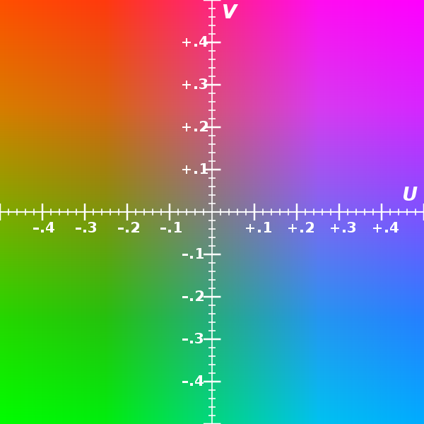
The UV plane
Now any HSL encoded image, when mixed with another HSL encoded image, is going to need special functions/encoders to mix those hue channels. What happens in analogue if we mixed two “Hues”? Do they wrap around with a modulus of 360 degrees? Is that a waveshaper? We can’t just sum them together, or that puts us out of range (instead of 90 degrees - 180 degrees = 270 degrees like we’d want, we get “INVALID HUE”.) Do we now need special “HUE INPUT ONLY” inputs on modules with modulus operators integrated? That’s going too far. We want to convert chroma into something that can be patched, mixed, have logic operators, etc.
So it’s much more powerful to place those kind of functions (Hue adjustment, Saturation adjustment) as part of a Polar-to-Cartesian waveshaper or rotation modulator, since now we can endlessly sum or cycle hue or adjust its rotary range as a part of the function (check out Navigator, it can do X8 rotations along a single 0-1V control input or rotate UV endlessly in either direction.)
Now, if you say “but I don’t care about mixing images properly, I want to mess with them!” Well in that case, nothing’s stopping you – combine those UV channels using any kind of analog transform (like the logic mixes on DSG3) and you will get something experimental, and likely interesting – or even demodulate UV yourself with multiplier modules – you can invent your own colorspaces or palettes. This is going to be much more organic feeling and less frustrating than a cropped angular range out of a converter. Or if you don’t like scientific recipes like HSL at all, just forget the HSL amp and invent your own transformations thru patching the basic ingredients (multipliers and summing blocks.) To put it another way, do you want your experimental chroma to be limited to a single textbook formula? Or do you want to design your own infinite angle extraction techniques from UV?
Then there’s the question of circles and squares. When we rotate hue, that is a sinusoidal transformation. It draws a circle around the center axis. Adjusting saturation is the length of the line (distance) the point is from center. If the distance is the same as the point moves, the saturation does not change. If the distance changes but the angle does not, saturation increases and hue does not change.
But how do you fit that circle into the full range UV plane? Is it oversized, does the circumference of the circle hit the corner points of the square UV plane? No we can’t do that, then your hue rotations would slide unnaturally and you would introduce cross modulation with Saturation when the UV positions exceeded bounds (that would defeat the point of Hue/Sat on separate signals.)
So what about just putting the circle entirely inside the square? Well that’s much better, and represents what a 2D hue rotation does – but if we convert Hue/Sat in that way to a signal, aren’t we cutting off the whole range of hues near the corner points? (Yeah.)
UV, on the other hand, contains the full picture of chrominance without any discontinuities. It can be converted to RGB and back again without losing any of the colors possible in the RGB colorspace, since it’s a direct linear matrix translation. You can sum two hue angles simply by mixing the UV components.
So my opinion? If you want to go “ultimate chroma” – yes, including angular displacements, the direct creation of UV thru hue waveshaping, control mixing, combination of opposing angles, etc then the obvious answer is UV signals + 2D/Quadrature processors. From my perspective, that’s the best of all worlds. A single module which can handle RGB input, RGB output, but still give you HSL transformations in between, or create RGB directly from HSL modulation inputs? You could patch an entire system up to generate that single Hue signal that gets sent into the HSL amp’s modulator. In other words, we don’t need an Angle output to do that – we can just turn any signal into an Angle!
#26 — creatorlars · 2022-01-18
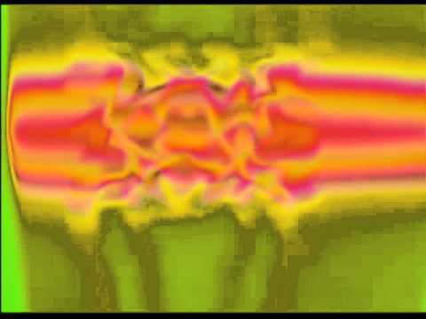
Here’s one of the first experiments I did when we made Mapper (originally Colorspace Mapper).
This patch is incredibly simple! The Luma channel of an external camera is patched directly to Hue angle, and the resulting HSL to RGB transformation is sent to the output after mixing with a single video oscillator. The camera is pointed at the display 90 degrees rotated, to create 2D bars.
Notice that every time the camera lines up with itself, the feedback goes nuts!
Throughout the video, I am doing lots of manual adjustment to Hue modulation depth and angle offset, as well as the final color encoder (in this case the original CVE, which is similar to the new ESG3.) If you encoded hue to a fixed angle instead, you would miss a lot of the tunability required to find some of this video’s best moments.
https://www.youtube.com/watch?v=CU8sLSim1Cc
#27 — dryodryo · 2022-01-18
Thank you again Lars for your very detailed and educational posts. I hope this is not taking you away from more pressing matters.
For my part, I definitely want both precision and crazy unpredictability. But if I could only choose one, it would be precision.
Before I even asked for “HSL as a signal”, I was aware of some of the complications you mentioned. Hue being an angular value, how do we convert that to linear, how do we wrap that value continuously, how do we combine signals, etc. Maybe I underestimated the complexity of the problem as it relates to your existing standard. The modulo math could be built into the HSL input of the conversion module… but if we’re adding Hues externally, we can easily exceed the limits of the +/- 1V LZX standard.
Regarding circles and squares, it was my understanding that a vectorscope shows the entire color space, with a circle indicating the legal range. Anything outside that circle is broadcast illegal. So although one might easily generate a signal with, say, R-Y = 0.5 and B-Y = 0.5, the resulting color/point in the extreme upper right corner is out of the legal range. Maybe that’s not so important nowadays. Certainly the old standards aren’t all relevant anymore, e.g. pedestal at 7.5 IRE seems very quaint and silly. But anyway, I was assuming that “HSL as a signal” would map to the legal range of NTSC, , i.e. a Saturation of 1 is coincident with the maximum legal limit, at the edge of the vectorscope circle.
In the end, I guess I have to grudgingly accept that an “HSL modulator” module is how it has to be. However, I still think it’s limiting in certain ways. It would be preferable to pipe Hue through some processing stages in the same way we can with Luma. But I get that it’s a big ask, and the constraints of the existing system design make it impractical.
It’s a shame, because although I get your point about doing anything you want on that R-Y/B-Y plane, it’s completely non-intuitive, not at all how artists see and think of color. Sure, the color wheel is a fictional construction, but it’s an extremely useful model that helps us conceptualize and get the results we want.
#28 — creatorlars · 2022-01-19
dryodryo wrote:
if we’re adding Hues externally, we can easily exceed the limits of the +/- 1V LZX standard.
Right, and that might be the biggest point I’m trying to make. It’s better if the range mapping is user controllable at the point at which it’s actually an angular displacement, and the user can fully control depth and scale of the map based on their input sources.
Because you’re paying the cost, either way. An HSL converter without hue modulation/displacement and multiple modulus thresholds is a huge circuit – so in my head I imagine a single converter like having a a giant synthesizer function — but it only loads 1 preset and there’s no adjustability. Or like driving a bus with no passengers. A lonely ride, even though you bought tickets for all your friends.
And user controllable doesn’t have to mean “imprecise” and it need not exclude “fixed” either. We can use below the panel trimmers and detent potentiometers to have a tunable input scale at the center position. Even if you like a fixed hue angle mapping constant, you’ll be glad the knob is there for some patches.
dryodryo wrote:
Anything outside that circle is broadcast illegal. So although one might easily generate a signal with, say, R-Y = 0.5 and B-Y = 0.5, the resulting color/point in the extreme upper right corner is out of the legal range. Maybe that’s not so important nowadays.
Well I’d have to think about that. I think that has more to do with chroma bandwidths in CVBS encoding – for RGB native path I don’t know if the colorspace gets limited in some way. I’m not a mathematician! But I understand the practical constraints very well.
And from that perspective it’s to our advantage to make sure anything that is passed as a colorspace signal/triplet can convert to and from RGB losslessly…
So an important question to me for any colorspace conversion is… Can you convert to and from RGB without losing anything across the whole range? In the case of YUV, the answer is yes! I am not sure if that passes through illegal colors or not at the extremes. But there’s enough headroom in the LZX signal path to make it happen even if it does.
The same is not true for an RGB - to - angle function though.
Another big reason to prefer UV as a transport format is that we’ve got a whole analogue system based around manipulating 2D planes for ramp and HV waveform sources already. So if we are transporting chroma as UV, all of those dealing with XY vectors or HV waveshapes are now Chroma processors and Chroma generators. If we can use all of those same modules for both “chrominance” and “spatial pattern synthesis”, the functional density of the modules practically doubles. We can spend more time on the “general purpose quadrature function generators” than on separate “chroma function generator” and “pattern generator” modules.
#29 — creatorlars · 2022-01-19
dryodryo wrote:
It’s a shame, because although I get your point about doing anything you want on that R-Y/B-Y plane, it’s completely non-intuitive, not at all how artists see and think of color.
I’m with you, but that’s where the HSL Amp comes into play. Think of what I’m proposing this way…
- Hue and Saturation are on the knobs & CV inputs.
- UV in and UV out are IO options
- RGB in and RGB out are IO options
#30 — Gavin · 2022-01-19
At a more meta level, I’d also massively caution (with my day job hat on as a uni academic in art history) against trying to bend the limits of the tools to meet an assertion of ‘how artists think about colour’ as being X or Y, especially for an experimental art such as this where what makes an ‘artist’ and ‘how to think about colour’ (and hell, in this discussion, even what colour is) are wildly up for grabs. You can barely convincingly assert that about professional paid artists in one place or time.
#31 — creatorlars · 2022-01-19
Gavin wrote:
‘how artists think about colour’ as being X or Y
Definitely! There’s a difference between “how art students are taught color theory in a painting class” (what I mean by the advantages of HSL colorspaces) and “how artists think about color” (it’s the goal of the instrument to empower, not dictate, that.)
When we’re turning the RGB knobs and finding the colors that resonate with us, we’re really destroying presumptions and designing our own colorspaces in the end. The maths just have to have a starting place that’s usable (RGB, YUV, HSL, etc.)
But there’s not really anything to debate when it comes to what color is in our medium (video.) It’s RGB or YUV signals values encoded in some way as an electrical signal. So whether or not we do something different with the signals, or interpret their relationships in different ways, we always need to reach an RGB or YUV conclusion. Otherwise it would not be video!
Every color you can generate with video already exists as a point inside this cube:
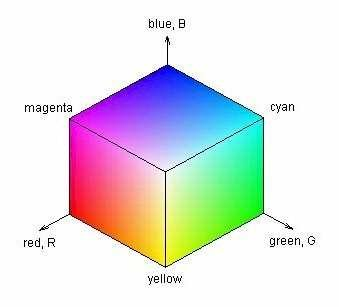
When we talk about colorspaces, it’s really a discussion of how we’re moving around inside that cube – the path we’re taking – when knobs are turned and values change. Hue selection (HSL) is unique in that you can have circular paths and rotational orbits. RGB moves the point 1 axis at a time. YUV traverses the cube diagonally on some axes.
And maybe that’s a good point to bring us back to the original idea of this thread: color modulation and animation. Whether we’re talking an image rate process like a colorizer, or a sub-frame rate process like an LFO animating a color channel, it’s all just paths between points in that cube. One is just happening faster than the other.
So RGB, YUV, HSL, whatever crazy matrix you made with a Matrix Mixer, etc – they’re just different modes of transit between the same list of possible RGB destinations.
#32 — creatorlars · 2022-01-19
dryodryo wrote:
In the end, I guess I have to grudgingly accept that an “HSL modulator” module is how it has to be. However, I still think it’s limiting in certain ways. It would be preferable to pipe Hue > > through> > some processing stages in the same way we can with Luma. But I get that it’s a big ask, and the constraints of the existing system design make it impractical.
I don’t think you understand. It’s not a “big ask,” it’s just a misunderstanding about how the math works for all this behind the scenes of graphics software. A fact that’s been hidden from you with code.
Hue is not a signal. Hue is a modifier. Every Hue slider you’ve ever adjusted, every color picker you’ve ever used, every hue value you’ve written in script or code, every hue-based blending mode you’ve applied. Even HSL encoded images. They are all modifiers describing a UV (and ultimately RGB) transformation.
Can we convert UV to a voltage representing the angle of Hue displacement? Yes. Still not a signal or a color channel. You’ve only converted the Hue modifier into a voltage describing it’s effect on the UV plane. This is just encoding the modification of a parameter as a voltage. This voltage only retains any association as a “hue” until you start trying to modify it.
Luma is a signal. Chroma/UV is a signal. Hue is not a signal. You could process the angle of hue displacement in degrees through processing stages, but what comes out the other end isn’t a hue. It only becomes “Hue” relative to the input of an HSL amp, which will always be processing or generating a UV plane.
If you want to “pipe Hue through processing stages” like you’re imagining, you can!! It’s even more powerful than you’re imagining! But it’s called “pipe UV through 2D processing stages, some of which might involve Hue and Saturation modifiers” or it’s called “use an arbitrary voltage to rotate the Hue of a UV source”. If you want rotation (Hue) or depth (Saturation) to be a part of your processing chain, you don’t try to turn those into signals – you just use Hue/Saturation modifiers to process your signal.
To make an analogy, X and Y coordinates are signals. But X Scale and Y Scale are not. Those are XY modifiers. You can have a number that represents a scaling operation, but that’s entirely relative to the XY coordinates you’re going to be scaling. The concept of Scale does not exist without XY, the same way the concept of Hue does not exist without UV.
#33 — creatorlars · 2022-01-19
And for anyone tired of this thread, here ya go…
#34 — dryodryo · 2022-01-19
OK, Lars, but correct me if I’m wrong, but we’re still not able to separate Hue and Saturation using generic XY or HV processors.You need to convert the cartesian UV coordinates to polar vectors. The “Mapper 2.0” module would do that, obviously, but nothing else would. Any transformation of U or V is going to affect both Hue and Saturation in non-intuitive ways.
And Gavin, I’m also a university level teacher/trainer, in 3D graphics. As I said earlier, the HSL model is a convenient fiction. But it’s ubiquitous, because it’s super useful. I can guarantee you, if you conduct a poll of artists, the number of them who understand how R-Y / B-Y color theory works will be close to zero. I’ve been doing video and computer graphics for 30 years, and I barely understand it.
Tools exist to meet the needs of users, not the other way around. Let’s not make rationalizations for why users should contort their brains, likely unsuccessfully, to accommodate the limitations of tools.
At the end of the day, any comprehensive attempt to modulate color (beyond raw RGB values) that does not incorporate the HSL model on some level is going to create barriers to entry for the overwhelming majority of users. We can argue that until we turn blue (or red, or green) but that won’t change the facts of how all artists have been trained and how nearly all color modulation is performed in hardware and software, dating back to the introduction of color TV.
#35 — dryodryo · 2022-01-19
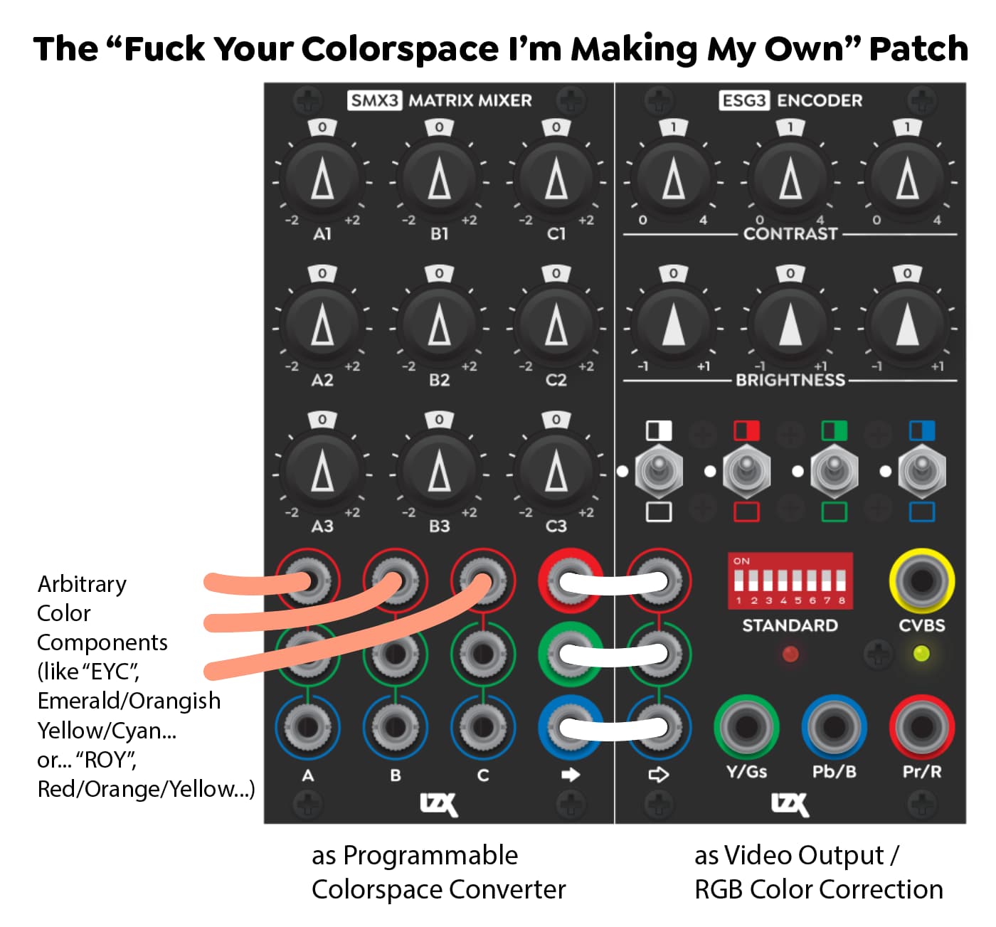
HAHA! Great title Lars.
When I was watching the Johnny Woods video on SMX3, I realized that this was possible and wondered why he didn’t demonstrate it. SMX3 is a complete color mixer. Add or subtract any color component from any other color component. Frackin’ genius.
#36 — creatorlars · 2022-01-19
dryodryo wrote:
OK, Lars, but correct me if I’m wrong, but we’re still not able to separate Hue and Saturation using generic XY or HV processors.
Sure we can!
A Saturation Processor is a Dual VCA. FKG3 is a Triple Fader which is even more than we need to turn it into not just a standalone Saturation proc – but one with some very interesting side effects brought on by its RGB logic modes. And also, it can be a UV/Chroma crossfader/mixer/keyer! The RGB out jacks just mean “unmodified.” In other words, if you patch YUV in, you get YUV (not RGB) out. And the RGB key modes become YUV key modes instead.
And a Hue processor is the same thing as an XY Rotator (like Navigator) or Polar To Cartesian Converter (like Mapper). UV in, rotate, UV out, and you change the hue without modifying saturation. The ART3 Affine Morph is perhaps even more crazy in this case, we could use it to multiply UV channels from different sources, or apply a trapezoidal displacement to the entire chroma space, or cycle the hue with a quadrature VCO.
All you need to use those modules in those ways is RGB/YUV conversion. That can be programmed manually with SMX3s. So really we could stop there and it’s already within reach.
You can think of the HSL Amp as a combination of all of the above: RGB/YUV conversion + rotator + polar-to-cartesian converter + a dual VCA + YUV/RGB conversion all under the same hood. If you want to think of doing more complex stuff, you get multiples – the complex things you’re doing are parts of the patch between a series chain of HSL amps, for example. It’s exactly what you’re asking for (a comprehensive approach to the HSL colorspace for LZX modular); just not in the form you’re imagining (that Hue/Saturation can be signals on cables.)
Tools exist to meet the needs of users, not the other way around. Let’s not make rationalizations for why users should contort their brains, likely unsuccessfully, to accommodate the limitations of tools.
Eh, we’re just talking about physics, here. Rationalization doesn’t enter into it – it’s just the shape of the world before us. With an analogue system we are building a graphics workflow from the bottom up (the user has control over the signal from its raw state and every function in between). So taking graphics concepts like Hue modifiers and applying them downward, without acknowledging their underlying abstractions, would just take us to “fuzzy overpriced Photoshop” rather than an analogue video synthesizer. Those abstractions are actual circuits that must exist physically on a board. Part of the point of all this is to not try to abstract things away. That’s what ultimately reveals some new technique that we’ve lost somewhere along the way in the development history of image editing and software GUIs.
#38 — dryodryo · 2022-01-20
7pip wrote:
Would you consider scheduling a few hours of your time to teach a small webinar to some of us forum users? If need be, you could even let me know the cost per hour to make it more feasible.
I would love to do that! And/or create some YouTube training videos. But I’m not ready yet.
First of all, I have exactly zero LZX modules in my possession at this time. I’ve got a few thousand dollars of LZX gear on pre-order!

Secondly, I feel like I have a lot to learn before presuming to be able to teach anyone else. Take a look at this thread, and others on this forum… it’s all about Lars schooling me! And I’m grateful!!
My rates for graphics training are kind of high. But, A) a webinar would distribute the cost among multiple learners, and B) I am doing this for LOVE and GOODWILL rather than profit, so I feel that steep discounts are in order.
Maybe in the spring or summer, once I’ve had time to work with the tools, we can talk about training.
Thanks for your interest!
#39 — dryodryo · 2022-01-20
creatorlars wrote:
A Saturation Processor is a Dual VCA. FKG3 is a Triple Fader which is even more than we need to turn it into not just a standalone Saturation proc
OK, but isn’t that an expensive way to do it? I’m thinking a straight-up video rate VCA would be more efficient. I.e. I don’t want to tie up a high level module to do a low level job like modulate saturation.
creatorlars wrote:
And a Hue processor is the same thing as an XY Rotator (like Navigator) or Polar To Cartesian Converter (like Mapper). UV in, rotate, UV out, and you change the hue without modifying saturation.
Great! So we daisy chain U and V signals through these modules, and Bob’s your uncle? Doesn’t seem like there’s much of an issue after all! Except rack space and cash, of course.
creatorlars wrote:
All you need to use those modules in those ways is RGB/YUV conversion.
That brings up a question. It looks like neither TBC2 nor ESG3 can send/receive YUV signals in LZX format. TBC2 accepts YsUV and provides Y & RGB outputs. ESG3 accepts RGB inputs and provides YsUV outputs. Is it at all possible for a firmware update to add YUV I/O functionality? At least to TBC2? It would be sweet to, once again, not tie up high level, sexy modules like SMX3. I mean, we’re already sending YsUV into TBC2. Can we just not convert it to RGB? Likewise, can we make ESG3 just not convert to YsUV, and merely add sync to an incoming LZX YUV signal???
creatorlars wrote:
With an analogue system we are building a graphics workflow from the bottom up (the user has control over the signal from its raw state and every function in between). So taking graphics concepts like Hue modifiers and applying them downward, without acknowledging their underlying abstractions, would just take us to “fuzzy overpriced Photoshop” rather than an analogue video synthesizer. Those abstractions are actual circuits that must exist physically on a board. Part of the point of all this is to > > not> > try to abstract things away. That’s what ultimately reveals some new technique that we’ve lost somewhere along the way in the development history of image editing and software GUIs.
I respect your design philosophy, but I don’t necessarily agree. The development history of any medium does tend to impose limits on our thinking and processes. However, that same history lets us leverage existing knowledge. Stand on the shoulders of giants, that sort of deal. Ideally, a good design finds the “middle path” between convention and innovation.
#40 — dryodryo · 2022-01-20
By the way, I thought about the fact that, since broadcast video U and V don’t have sync on them in the first place, we could just plug them directly into the system. But then I remembered that the voltage levels aren’t the same.

#41 — creatorlars · 2022-01-20
I would love to do that! And/or create some YouTube training videos. But I’m not ready yet.
Personally I would enjoy any educational content even just from the angle of what you’d normally consider “advanced graphics and animation for video professionals”, outside of analog tools at all. I am familiar with many software tools you teach that I still have no real practical experience with. But I can also subscribe to get access to some of your courses already. I miss Summer School at the Community TV station.
OK, but isn’t that an expensive way to do it? I’m thinking a straight-up video rate VCA would be more efficient. I.e. I don’t want to tie up a high level module to do a low level job like modulate saturation.
I look at the cost this way – It almost always works out least expensive to have a single module that fits multiple roles well, than to have multiple modules that fit single roles well. So with modules like SMX3 and FKG3 for example, it’s not that you permanently relegate them to “lesser duties” – it’s more that, contextually, every time you patch, you can use them that way without having to buy another module.
To put it another way: The lowest cost system is the one where you can use every module in every patch!
So practical/realistic system example – you’re a video artist who vibes with HSL colorspace. You’ve got an HSL amp and couple FKG3. The HSL amp is your primary Hue/Sat modifier, your system’s “color picker”. But one day, you have a patch where you really want to pre-process Saturation to apply some animated beating to make your chroma hit a peak spot intermittently, that makes your feedback look AWESOME. These are the cases where you’re glad for that extra degree of functional versatility that FKG3 can provide, because thinking outside the box, that module can do so many things. It’s designed that way, “KEYER” is just a prompt, a “step 1”.
Likewise, can we make ESG3 just > > not> > convert to YsUV, and merely add sync to an incoming LZX YUV signal???
That’s a bit tricky. Because yes, you can get RGsB out or YPbPr out from ESG3. But both presume an RGB input. If you put in YUV to ESG3, you will get a viewable signal, but the bottom half of the UV signals (the negative portion) will get clipped off by the Blue/Red clipping circuits.
I agree, this would be nice. For TBC2, YUV output is definitely something we can consider. In fact we should be able to do that at zero processing cost in the FPGA by using only the CSC already built into the TBC2’s output encoders (ADV7393.) We could also have an SMX3 style “programmable CSC matrix” as a software function. (The TBC2 procamps right now are on the frontend, but the outputs have CSC matrix too)
Like I mentioned up thread, unlike polar-to-cartesian and rotation circuits (big, expensive, circuits) a fixed RGB-to-YUV and YUV-to-RGB translation is actually quite cheap. 6x opamps (input, output buffers) and some passive resistors is all you need. So on the “low cost utility” angle, bidirectional YUV/RGB conversion is, as it were, a “small ask.” If we can keep things 12HP – it makes everything more easy to achieve. So that’s why I was thinking, a low cost color utilities module might be worth some further thought. Or a “multi utilities” the way DSG3 is for shape (switch for colorspace converter select, etc.) These kinds of modules are best thought out after we get lots of feedback from patching the first set of Gen3 modules, so there’s lots of room to discuss it.
#42 — creatorlars · 2022-01-20
dryodryo wrote:
By the way, I thought about the fact that, since broadcast video U and V don’t have sync on them in the first place, we could just plug them directly into the system. But then I remembered that the voltage levels aren’t the same.
That’s a great point. But that’s where SMX3 comes in, and exactly why all those knobs go to 2X instead of just 1X gain. So broadcast spec? DC black level perfect? Maybe not… but you can break those rules. The gain doesn’t have to be perfect. That’s part of what’s great about the format, is that sync is going to be stable on the output no matter what you’re feeding into the signal path upstream. All the first tests of video input to the system were done this way – component video directly into the matrix module.
#43 — creatorlars · 2022-01-20
Another point on 75 Ohm video transmission direct to 3.5mm jacks:: You’ll already be coming in hot with PbPr. Typically UV are +/-357mV post-termination. But before termination they are +/-714mV. If you go direct to a 3.5mm jack your input impedance is 100K, not 75R. So you’re not really going to have the typical halving effect. The transmission’s signal integrity may not be ideal, but it will work.
#44 — creatorlars · 2022-01-20
dryodryo wrote:
I respect your design philosophy, but I don’t necessarily agree. The development history of any medium does tend to impose limits on our thinking and processes. However, that same history lets us leverage existing knowledge. Stand on the shoulders of giants, that sort of deal. Ideally, a good design finds the “middle path” between convention and innovation.
We have a very specific philosophy about this, it’s true. The initial premise of this project is that we wanted to pick up the torch of analogue image processing from the point in history when it was put down, and abandoned for computer graphics based technologies. So it is intentionally an exercise in anachronism (what were they working on, with analog, before the computers took over?), in treasure hunting (where else could they have gone with it, that computers did not go?) , in detail seeking (what did we miss, were there ideas that were half realized?).
And in that sense, we’re here specifically to find the counter approaches, that may be coming from a perspective more rooted in the hardware of the analogue circuitry itself. We want to be informed by the process constraints of analogue computer implementations, and we want the UI to be informed by those constraints as well. For example, we’d much rather explore the completely alternative ways to approach chroma processing (like vector processing of UV quadrature signals) rather than adopt the way graphics software already approaches the problem.
#45 — dryodryo · 2022-01-20
creatorlars wrote:
The initial premise of this project is that we wanted to pick up the torch of analogue image processing from the point in history when it was put down, and abandoned for computer graphics based technologies. So it is > > intentionally> > an exercise in anachronism
Well, you didn’t stick with that premise with Memory Palace, did you? I mean, it seems like an evolution of the Fairlight CVI. So you’re open to digital gadgets. For me, the question is not so much of how exactly the inner guts work. Analog and digital are just tools, and you pick the best tool for the job. The main concern for me is the FLOW of the working PROCESS. 3D animation, for example, is a generally frustrating process due to high complexity combined with low interactivity. It’s not at all like what I envision the perfect video synth experience to be… playing a real time instrument that has immense flexibility and responsiveness. Yes, you trade off the complexity, you’re going into a simpler realm. So from that point of view, sure, I’m down with the anachronism concept. But you know, a Eurorack module does not have to be analog to be useful, powerful, exceptional.
creatorlars wrote:
That’s a great point. But that’s where SMX3 comes in, and exactly why all those knobs go to 2X instead of just 1X gain. So broadcast spec? DC black level perfect? Maybe not… but you can break those rules.
There you go again, using my super advanced rocketship module to deliver the mail. There are some voltage conversion options out there, I have to do more research, figure out which ones are fast enough. The only fly in the ointment with this plan: the sync-stripped Y channel coming out of TBC2 is going to be delayed relative to U and V. So they would have to go through video delay lines, which it turns out are hella expensive. Or else just live with the effect of the chroma coming in one frame early.
creatorlars wrote:
For TBC2, YUV output is definitely something we can consider.
Yes please!!
On the output side, I’d be delighted with a simple voltage conversion and sync insert on Y. Not within your parameters of 12HP/$400. But maybe someone could come up with one. Or maybe you can do a future version of a high level encoder like ESG3 that can handle YUV input.
The prospect of an all YUV workflow is sounding more attractive the more you tell me.
#46 — creatorlars · 2022-01-20
dryodryo wrote:
Well, you didn’t stick with that premise with Memory Palace, did you? I mean, it seems like an evolution of the Fairlight CVI.
The design concept for the Orion series was similar, but displaced in time. It follows the same ethos of anachronism and treasure hunting. The Fairlight CVI is maybe even the best example of what we look for, which is unique ideas brilliantly implemented, that were reaching for an evolution of format … but never got a sequel (or maybe, the sequel could have been something else, something interesting, but a different path was taken.). So the prompt mainly just shifted timelines from the late 60s thru early 80s, to the early 80s thru late 80s (pre Video Toaster era.) But the prompt was “What if video never became a part of the personal computer, and mid 80’s concepts of hardware DVEs and attempts at ‘video instruments’ like the CVI, had followup instruments?”
None of it has anything to do with analog vs digital, really. Video itself is a hybrid signal, and some of the very first video art uses digital techniques and lo-bit computers (Video Weaver, for example.) For us it’s more about the idea of revisiting a period in history, observing the state of video technology at that point – looking at the state of things now – and trying to find out what exists in the gap, if there is one. The thesis is based on the idea that technology moved so fast through these years, that we must have left some great ideas behind.
In another 10 years, maybe we’ll have wrapped up some of these ideas and be moving onto a different “WHAT IF…” this time, focused on the early evolution of PC graphics cards, game console wars. I mean 1990s graphics software has some of the weirdest ideas I’ve ever seen!! I know there are plenty of lost ideas there.
Graphics software evolved to use color pickers and HSL controls pretty much exclusively – especially if you’re writing software code, manipulating colors thru animation, etc, HSL is it! It’s something software excels at. “100x hue sliders with different easing curves and start/stop times” is the kind of scripting trick that got me jobs doing Flash animations in the early 2000s.
But for hardware circuits and patching, and dense, exciting creative systems, the UV quadrature approach is seeming to me, to be what is “the natural answer.” It backs up on the stuff the computer is best at (HSL and billions of parameters) and doubles down on what modular analog systems are best at (fully interpretive signal paths and instantaneous results, very complex transformations being represented as two patch cables instead of a long custom script, etc).
Analog approaches don’t have to be simple – it would take one hell of a computer to simulate in real time what even a small sized LZX system is doing (from a CPU’s perspective, every single 3.5mm IO jack in your system is an HD rendering thread!) But analogue approaches do need to be simple to interact with, and digestible enough to reinterpret creatively.
I appreciate this conversation, thank you.
#47 — creatorlars · 2022-01-20
dryodryo wrote:
The prospect of an all YUV workflow is sounding more attractive the more you tell me.
I am really thinking it may be the way to go for many artists. I am into “saturate the heck out of it all, RGB madness, primary colors! palette morphs, rainbow patternmaking psychedelia” etc. Which is more RGB focused. The YUV space feels more subtle in comparison, speaking from how it feels “to put your hands in it.” Having Luma on its own channel prompts you to do a value study of your composition before any color is added. And that separation makes it easier to have color hit only peak spots or intermittent moments with the chroma components.
Also, while UV components do feel a bit awkward for picking a specific color on 2 knobs , what they really excel at is “finding interesting and beautiful gradients.” In a video synth, the latter is often what you’re looking for more than trying to find emerald green like you would with a color picker tool.
#48 — Gavin · 2022-01-20
Absolutely. Any artist begins in the middle of those positions you describe. How do performance artists think about colour? After all, they’ve one of the dominant artists’ groups who have shaped video art. I don’t think they have a HSV chart in one hand to consult. Any more than painters who once had a class in colour theory do, as you say.
That middle contains tools, too, of course, which have always determined the theory (whether we’re talking paint pigments or CRT screens). it’s great that in designing the tools, you have this understanding and sensitivity to the variety of current art practices outside the dominance of computer graphics (and the blindness and assumptions that can cause) and the actual material history of video art, where the line of tools/art is not a clear technical division at all. The tools were the art - It would be completely incorrect to try and understand eg. the Dan Sandin modules some of your modules are based on in terms of Sandin having some kind of consumer/enduser mindset!
During lockdown, I couldn’t get my MA history students into the V&A to open up the computer art archive like I usually would, so I just did a zoom lecture on early video art organised by techniques and tools, and piped through my expedition modules with appropriate patches for each artist (castles for Steve Beck, getting out the oscilloscope for Steve Rutt and Bill Etra). It was a surprisingly instructive to do!
Maybe you need to put some fun switches on this module for truly outmoded paths around that colour cube: Cennini, Ladd-Franklin…
#49 — dryodryo · 2022-01-20
creatorlars wrote:
Analog approaches don’t have to be simple – it would take one hell of a computer to simulate in real time what even a small sized LZX system is doing (from a CPU’s perspective, every single 3.5mm IO jack in your system is an HD rendering thread!) But analogue approaches do need to be simple to interact with, and digestible enough to reinterpret creatively.
I appreciate this conversation, thank you.
The pleasure is all mine, it’s a very stimulating, educational process for me. If I’m able to contribute something to your design process, I’m honored.
WARNING: nerd alert! Regarding analog and digital, rendering threads etc. – and this is veering off topic – on the computer, the bottleneck isn’t image processing. It hasn’t been for a while. Especially with the last few generations of GPUs, we’ve actually far outstripped Moore’s Law. Manufacturers just keep packing more and more cores onto these chips, now it’s in the thousands. (I just looked it up, an RTX 3080 card has 28 million transistors.) The bottleneck on the PC is storage. Not necessarily storage space, but definitely bandwidth. Your choices are A) compress the hell out of your footage, B) spend a fortune on a RAID, or C) be content with just one or two channels of simultaneous disk I/O. This is going to change with faster PCI bus standards, wider adoption of Thunderbolt, and ultimately even faster forms of SSD tech. But anyway, if you’re just talking about “take this moving image and do something to it in real time”, today’s PCs are quite adequate for that task. I mean, look at all the killer video stuff people are doing with Raspberry Pi, which is a very low end platform from the point of view of the type of work I do.
#50 — creatorlars · 2022-01-20
dryodryo wrote:
Not necessarily storage space, but definitely bandwidth.
Exactly – memory bandwidth is the limiting factor. That’s why FPGA based platforms are so appealing, is that you can have a dedicated custom “GPU” inside the FPGA maximizing what can be done with the embedded system’s bandwidths in a fixed environment. But even something like Memory Palace or TBC2 has maxed out the memory bandwidth required for 7-8 concurrent video streams (analogue doesn’t even blink even if it’s well beyond that number.)
When I say rendering, I’m of course excluding hardware acceleration or GPUs – and I’m presuming a CPU is treating the stream the way an analogue computer does; as a real-time constant value. I’m also presuming that something is being rendered pixel-per-pixel – modern GPUs accelerate this in all kinds of ways, but they also abstract a lot of behind the scenes access to textures and memory. I love letting modern GPUs do their thing – I’m not trying to compete with that.
But as all of us have been in consent about in this thread, tools inform the output! And art created on a foundation of technical abstractions is going to inform the range of work created with it – even if, on paper, those abstractions are more powerful. You can see the recent trend in gaming towards pixel-art rendering as evidence that even the game industry is recognizing that sometimes you need to get into the point-by-point details to achieve certain artistic aims.
To put it another way, there’s more than one way to make a GPU! The type that dominates PC/console gaming and mobile architectures is highly optimized for those purposes. There are a lot of things they don’t do well. And it’s not that those are “better” things. They are just “interesting” things. And I’m interested!!
#51 — dryodryo · 2022-01-22
I was actually talking about storage I/O bandwidth, but yeah. Memory bandwidth too. Analog doesn’t suffer the latency of things like memory caching, which is great. But on the other hand, if you don’t have any money, you don’t have to pay taxes.

On the subject of analog computing, this is the area I would like to see developed. 90’s era graphics oddities are of limited interest to me. I admire the kind of work Joost Rekveld is doing, resurrecting and expanding old analog computers for abstract vector graphics. There’s a deep connection between analog computers and video synths. And yet video synths never developed any higher brain functions. You’re lucky if you get logic gates and basic arithmetic. I would love to see proper patch programmable video computers… trig functions, imaginary numbers, linear algebra matrices, the works. My math skills are crap, but the availability of something like that would really set a fire under me to do the learning required.
#52 — creatorlars · 2022-01-22
dryodryo wrote:
There’s a deep connection between analog computers and video synths. And yet video synths never developed any higher brain functions.
Absolutely! You can think of the LZX modular as an analogue computer for RGB graphics at its heart. SMX3 is a linear algebra matrix – the Polar-To-Cartesian and Affine transform circuits we’ve talked about in this thread a bit are powerful analogue implementations of DSP functions used in graphics and GPUs. But there are still many functions and implementations to explore.
A big practical advantage of the video synth over a traditional analogue computer or even an audio synthesizer is that it doesn’t have to be as precise or in “tune” as a computing environment for numbers or music – we can adjust it by feel and find what we want to see. And that makes all the difference in the world, as it’s what puts all of this into the realm of possibility for an individual artist (it’s not cheap of course, but ~$4,000 vs ~40,000 is a huge difference when it comes to buying an instrument.)
This isn’t nearly capable of processing video, but this project looks all kinds of fun!


https://the-analog-thing.org/Analog Paradigm presents a modern open source, educational, low-cost analog computer.
Link: The Analog Thing: Analog Computing for the Future
#53 — dryodryo · 2022-01-22
“THAT” looks pretty cool. It could potentially be useful for modulation. But again, we need a bank of voltage scalers… it’s +/- 10V.
SMX3 may be a 3x3 matrix by some definition, but if I’m not mistaken there’s no mechanism for performing matrix math. I mean, there are no outputs for individual values, so I don’t see how we could, e.g. multiply two matrices. But I am out of my depth here.
But back to the topic… color. Have you thought about a Y/C patch paradigm? Chroma IS a signal, where saturation is represented by voltage level and hue represented by phase. I’m thinking that any module with a sync input that can recognize color burst should be able to process saturation and leave hue alone. To modulate hue, there would need to be some mechanism to offset phase relative to color burst reference. Not sure how that works technically, if it’s feasible to tweak phase without using delay. I.e. different standards use different burst frequencies.
I know this harebrained scheme would result in lower color resolution than UV. But I’m just throwing out ideas. Still clinging to my HSL assumptions. But, to paraphrase Pascal, nature is only first habit.
#54 — creatorlars · 2022-01-22
dryodryo wrote:
SMX3 may be a 3x3 matrix by some definition, but if I’m not mistaken there’s no mechanism for performing matrix math. I mean, there are no outputs for individual values, so I don’t see how we could, e.g. multiply two matrices. But I am out of my depth here.
One value is set by the fixed -2V to +2V voltage of the knob position, and the other value is set by what’s patched into the input. It is a fixed matrix, just like a colorspace converter in graphics/DSP terms (which has 9 programmed multiplier coefficients). A version with 18 jacks instead of 9 jacks + 9 knobs is a potential variation on SMX3, and I can imagine that being part of our range of modules. But either way, it’s a 3X3 matrix transform – whether the inputs are from knobs or jacks is a question of the user control implementation. (It’s the same circuit, either way! SMX3 is a fully electronic gain controlled instrument, there is no passive control or attenuation of the input signals.)
But back to the topic… color. Have you thought about a Y/C patch paradigm? Chroma > > IS> > a signal, where saturation is represented by voltage level and hue represented by phase.
Sure! But that is a Composite video processor – and that opens up a huge can of worms design complexity wise (and it would limit us to NTSC/PAL only). On the other hand we can treat YUV/RGB similarly by the same signal paths and modules.
There’s nothing preventing that by the spec though! It’s just that composite video is passed on RCA connectors and not part of the 1V signal path that RGB/YUV can be.
There’s no such thing as “HD chroma subcarrier”, at least not as far as video standards go. It could be possible, but not practical.
In some cases “YC” video in terms of digital encoding is referred to as Luma/Chroma, like the BT.656 spec with YUV 4:2:2 encoding. But the “C” is actually UV in those cases. Every other “C” sample is either U or V.
The main point is that RGB and YUV are linear voltages. Chroma modulated subcarrier is not – the hue value is encoded as a phase, and the saturation is encoded as amplitude – even though the signal is passed as a voltage, neither hue nor saturation can be identified by the value of that voltage at a point in time (you need subcarrier demodulation, aka chroma to UV decoding, to do that.)
#55 — creatorlars · 2022-01-22
dryodryo wrote:
Still clinging to my HSL assumptions. But, to paraphrase Pascal, nature is only first habit.
I was thinking on this more, and I think stereo audio is a good analogy for UV as Chroma. And a PAN control is a good analogy for hue or saturation controls over UV.
For example, most audio mixer strips don’t have separate Left/Right gain controls. They use a single “PAN” control – this single control is effecting a dual channel (Left/Right) signal path, even though it is just one knob. That’s directly analogous to a Hue/Sat control in the UV proc/mixer context.
To make another audio analogy, a mastering processor or the audio mixer’s output section isn’t going to have pan controls. It’s going to have the Left/Right gain controls separately. This is analogous to “mastering” your video path by calibrating UV while looking at a vectorscope, etc.
#56 — dryodryo · 2022-01-23
creatorlars wrote:
There’s no such thing as “HD chroma subcarrier”, at least not as far as video standards go. It could be possible, but not practical.
OK, then forget it! Bad idea, but worth asking. I guess.
#57 — 337is · 2022-01-23
Could you possibly add basic definitions for Polar & and Cartesian in analogue video use to your vocab list? I grasp them, but barely …
#58 — Jesse · 2022-01-23
A version with 18 jacks instead of 9 jacks + 9 knobs is a potential variation on SMX3, and I can imagine that being part of our range of modules.>
Oh please make it so! All I’ve ever wanted was a VBM with jacks instead of pots

#59 — creatorlars · 2022-01-23
337is wrote:
Could you possibly add basic definitions for Polar & and Cartesian in analogue video use to your vocab list? I grasp them, but barely …
Definitely! It’s easier for me at least, to understand it visually. Here’s an image from a CNC website I borrowed that illustrates it plainly and simply:
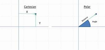
In the above image both “Cartesian” and “Polar” are identifying the same point in the graph, they are just recording it in different ways. One with XY values (Cartesian coordinates) and one with Angle/Distance (Polar coordinates.)
Now let’s replace “XY” with “UV” and we have different words for the same thing:
Angle = Hue
Saturation = Distance
To relate this to our discussion of chroma, review the “Chroma plane” as posted earlier up.
Now let’s define a chroma value called “Lavender” in Cartesian coordinates (UV).
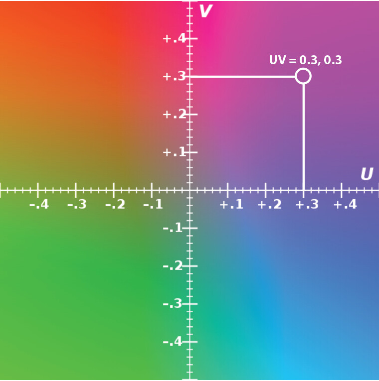
Now let’s define a chroma value called “Lavender” in Polar coordinates (Hue/Saturation)
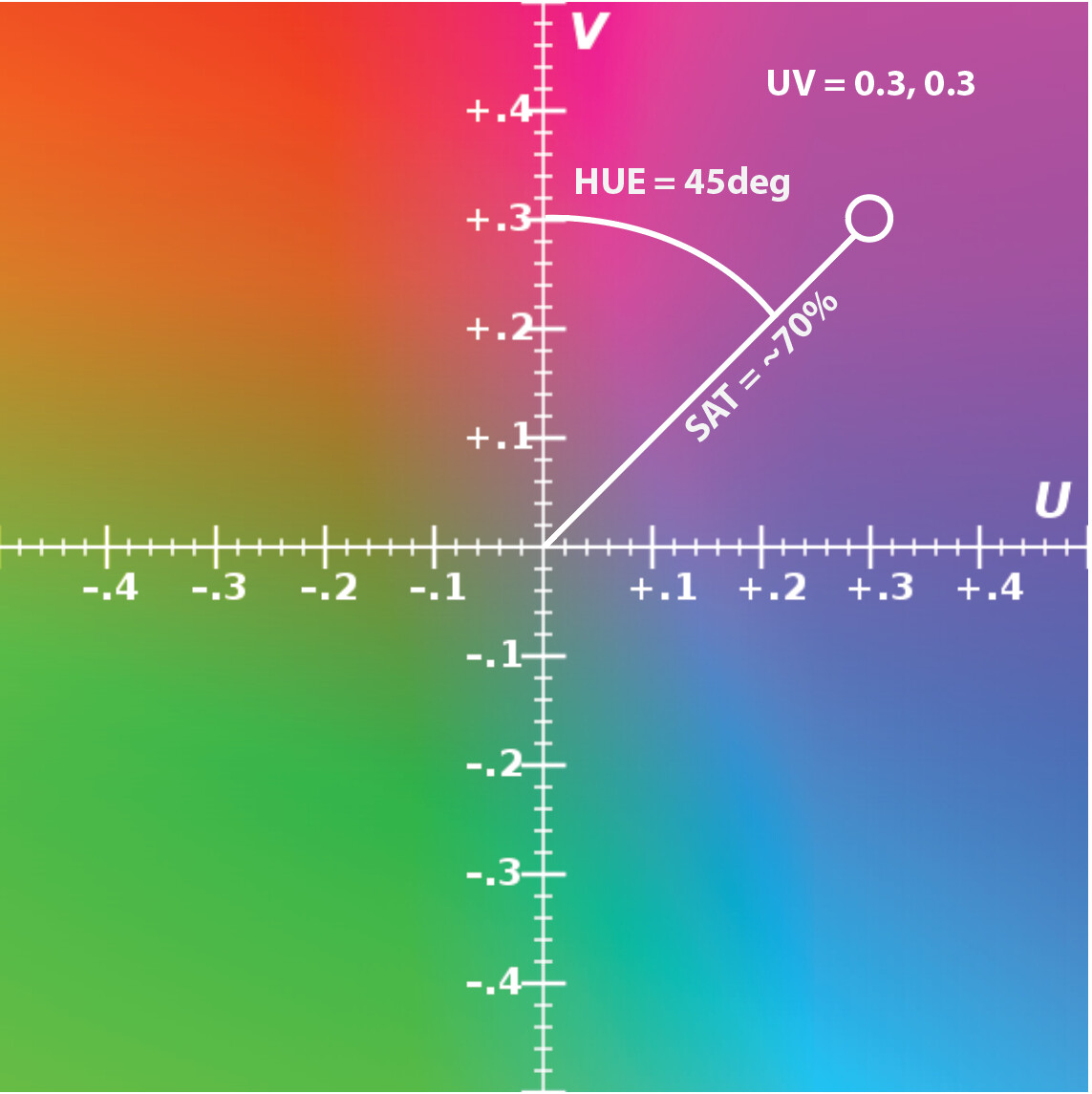
So a “Polar To Cartesian Waveshaper” takes inputs representing Angle (Hue) and Distance (Saturation) and converts them into UV values.
In electronics function blocks, polar-to-cartesian transform involves…
n * Sawtooth To Triangle waveshapers, where n = ((total span in degrees / 360) + 1) * 2
2 * Triangle To Sine waveshapers
2 * Linear VCAs
This is such a complex circuit that it’s been denoted a “complex function block”, and therefore worth having its own user facing implementation (as opposed to just expecting the user to patch it across multiple raw functions.) And that’s the point of modules like Mapper (or the HSL amp discussed in this thread.)
#60 — creatorlars · 2022-01-23
dryodryo wrote:
OK, then forget it! Bad idea, but worth asking. I guess.
I hope you don’t feel like I’m shutting down the brainstorm – cataloging all possibilities our minds could conjure and looking at intersections is how we developed all this in the first place! And of course, the answers we ended up with aren’t the only approach. But I really like being able to describe how we ended up where we did, and why, and where there’s still a lot left to consider. 50 years from now, maybe there is another LZX, and they can read these words, and take up where we left off. Or try something totally different and apply these early 21st century concepts to their holo-projectors and retinal implants.
We’ve talked a lot about how that if you have an FPGA powered scaler/encoder and scaler/decoder, that “what’s in between” doesn’t even have to be a feasible video signal at all. Chromagnon is experimenting with that a lot (non-standard decimated rasters for laser output, etc.)
#61 — creatorlars · 2022-01-23
Jesse wrote:
Oh please make it so! All I’ve ever wanted was a VBM with jacks instead of pots
I’m into it. These first 5 modules have to be super dense and functional as a core, mainly for the practical reason that we really want < $2000 video synths to be a reality. So 3-5 modules have to complete the picture of a full instrument, and there have to be several possible instruments you could make in that price range and size. After that is in place, the following designs don’t have the same constraints!
I want more modules that are “jacks only” in general though. And some modules that are (cheap!) and just “voltage generators” to go with them.
#62 — nerdware · 2022-01-23
I can imagine a logic module being jacks only. Like a combo of elements from the old Visionary binary modules, but in the Gen3 format.
#63 — dryodryo · 2022-01-23
creatorlars wrote:
I hope you don’t feel like I’m shutting down the brainstorm
Absolutely not. You’re just telling me what’s feasible.
creatorlars wrote:
50 years from now, maybe there is another LZX, and they can read these words
Pish posh. LZX is going to outlive all of us!
Regarding control voltage of pots such as SMX3, this is high on my wish list. I’ve got three Bahascillators sitting here crying out to send tri-phase waves into a color component mixer. is it reasonable to consider a hardware revision of existing modules to add CV expansion headers? Then all one would need is a ribbon cable and some jacks.
#64 — creatorlars · 2022-01-23
dryodryo wrote:
is it reasonable to consider a hardware revision of existing modules to add CV expansion headers? Then all one would need is a ribbon cable and some jacks.
The cost-per-HP is pretty flat in how we’ve designed/optimized Gen3 series. In other words, a 24HP SMX3 that included a 3X3 multiplier CV input matrix (in addition to the knobs and jacks) is going to work out to a similar cost as 2x 12HP SMX3s already do. Audio circuit design can jump past a lot of the infrastructure cost (low noise integrated power, individual IO buffers for every single jack, etc) that we need to employ to ensure performance consistency.
Also, just from a personal perspective, I feel like “expanders” are kind of redundant and bad design, in a system that is already intended to be modular – where all modules are by definition, expanders to each other. The exception is when the expander lowers the cost or solves some production related issue that serves the user better or amplifies the value of their investment. So if we could make a multiplier expander to SMX3 that only costs $50, then that would be well worth it! But if it costs the same as another SMX3, then it’s better design to just make the expanded function a unique thing.
So the 12HP option is about making a $399 matrix possible, so that you can complete the picture by combining that function with other modules like SMX3+FKG3 (matrix crossfader/keyer) or SMX3+ESG3 (make your own colorspace style output amp) or SMX3+DSG3 (minimal color graphics synthesizer). It’s in these kinds of pairs that the Gen3 modules really start to take on specific workflow/instrumentation identities.
There are of course, bigger than 12HP functions that would need to be behind a single module to exist efficiently – a 24HP “Matrix Multiplier” is a good example of that.
#65 — dryodryo · 2022-01-24
To paraphrase, it makes better sense from your design and business perspectives to build bigger modules rather than expander options. Additionally, cost per HP is constant. By that I assume you mean all costs… development, parts and labor, and wholesale/retail.
Fair enough, I was thinking of configuration flexibility. My specific example was of a simple, dumb CV expander rather than a full blown matrix multiplier. I wondered if it would be cheaper to build a CV expander by retrofitting the existing module, rather than designing a new module with a new interface board. I mean, obviously you’ve already optimized the existing module for space, function, controls… and cost.
#66 — creatorlars · 2022-01-24
dryodryo wrote:
To paraphrase, it makes better sense from your design and business perspectives to build bigger modules rather than expander options. Additionally, cost per HP is constant. By that I assume you mean all costs… development, parts and labor, and wholesale/retail.
We base our pricing for modules on a multiple of direct costs (parts cost + assembly labor costs) only. So you are always getting what you pay for, in the sense that the price tag isn’t based on a valuation of what the market could potentially bear – but instead rooted in how much it costs us to manufacture the product (video op-amps, high grade potentiometers, skilled technician labor). We have to set the ratio of retail price to direct costs appropriately in order to cover all the indirect costs (development, sales, support, etc.)
So if our business is doing well (selling more modules), we can expand our R&D team, and that means more opportunities to do more new designs and develop our ideas more quickly.
dryodryo wrote:
My specific example was of a simple, dumb CV expander rather than a full blown matrix multiplier.
In the LZX ecosystem there’s not really such a thing as a “CV” in the sense of a lower cost or lower order function block. Every modulation input is a wideband (video modulation capable) function. Every input and output jack is buffered directly by a video op-amp, whether it’s part of the main signal path or the modulation path, and as of Gen3 any attenuator knob is controlling a wideband VCA.
So the price tag relates most directly to the number of IOs and knobs, and the size of the panel (because that infers a consistent processing ecosystem behind the scenes, which also infers a consistent cost of low noise power behind that).
Most modules falling in the complex analogue range (like FKG3, SMX3) will likely ride the ~$33 per HP average these modules already do.
Simple analogue modules like mults and summing blocks (none yet announced) will possibly be able to drop lower than that (maybe closer to ~$25 per HP.)
But an expander module becomes a simple analogue module with a special feature, which brings us right back to “complex analog” in costing. So with an expander, it’s just not worth it. We end up with 2 products, one of which requires the other for operation. Better to solve it with 2 products, each offering its own functional footprint. Ideally that would be two 12HP modules, which when combined together, offer the desired expander functionality (like maybe an SMX3 with knobs + an SMX3 with jacks.)
#67 — dryodryo · 2022-01-24
Thanks again for your detailed and helpful posts.
creatorlars wrote:
In the LZX ecosystem there’s not really such a thing as a “CV” in the sense of a lower cost or lower order function block. Every modulation input is a wideband (video modulation capable) function.
It sounds like SMX3 already is a video matrix multiplier, but that functionality is not exposed by the panel board.
The issue I anticipate with a jacks-only version of any module is the unfulfilled need to tweak the incoming modulation signal. E.g., I’m sending a +/-1V oscillator into a “CV” input, but the modulation amount needs to be attenuated. Now, it looks like the Fox Access will serve this purpose quite nicely, but at this point of my system plan I’m already worried about rack space. I.e. don’t want to use up too many HP with utility modules.
For my own work in the software synth realm, I’ve added a gain and bias to literally every CV input… it costs me nothing and gives me everything. But obviously I am not dealing with any of the constraints of hardware.
#68 — creatorlars · 2022-01-24
dryodryo wrote:
It sounds like SMX3 already is a video matrix multiplier, but that functionality is not exposed by the panel board.
Correct – SMX3 is a “fixed” matrix multiplier if we look at the inner circuitry, just like a color space converter.
The issue I anticipate with a jacks-only version of any module is the unfulfilled need to tweak the incoming modulation signal.
Right – and that’s a perfectly valid concern – we’d need to put some work into the design of an SMX3 followup, in order to find the correct functional footprint for a follow up module. That all starts with answering the question… “What are you trying to patch? What other modules are in that patch? How are they going to interact? Can we already patch this in some other way? Is this module useful in a small system? Is this module redundant in a large system?” etc. We collect use case data from answering these questions, and that all informs the process of deciding the front panel layout, its IO, size, and its controls. Maybe it turns out that the matrix multiplier is better implemented as 9x single multipliers on the same panel, but laid out in a normalization scheme? Maybe that’s most efficient as a giant VCA utility bank, and matrix is just one of the things you can do with it? Or maybe “matrix multiply” is a mode on a more focused RGB operator module? Maybe it should have two sets of 3 inputs, like a keyer, with a global morph control? If “raw function access” in lieu of context is the hope (which is valid too!) then we don’t need a matrix multiplier – we just need a minimal multiplier or dual multiplier module, and you could just get a stack of those and patch whatever you want. There are dozens of ways to approach it.
Doing a lot of that work (and building on earlier generations of projects) is how we arrived at the design for SMX3, for example – and how getting that specific function footprint (fixed matrix) into a 12HP module was going to be a big win in terms of its patchability and role in the context of the system.
For my own work in the software synth realm, I’ve added a gain and bias to literally every CV input… it costs me nothing and gives me everything. But obviously I am not dealing with any of the constraints of hardware.
Right – the resources are different.
In hardware/analogue the resource is IO, control, rack space, power infrastructure, buffering infrastructure, embedded system infrastructure, and after all that – “application circuit.” So every IO point or control point counts, and the application circuit is often the least factor when it comes to your resources.
In software the resource is often processing power or memory bandwidth as it relates most directly to the “application circuit”, or the rendering computation itself. For example rendering 1 output may use a percentage of the available computation power. But the actual parameter modulation that sets the properties of the rendering happens very slowly, only once per frame. That’s why you can have nearly limitless controls or modulation IOs in a software instrument without running out of computation capabilities.
But with software parameter CV inputs, you’re not enjoying the benefits of “wideband” modulation. Parameter values are presumably only going to be sampled once per frame by whatever is doing the output rendering – so if you were to try to accurately emulate the hardware case, you’d have to include a series pipeline of texture operators for every individual CV input/attenuator.
So they are both constrained, but in different ways. Analogue is constrained by physical IO/Control footprints. Software is constrained by the platform’s computational/memory limits.
#69 — 337is · 2022-01-25
Wow, that is a super clear explanation of Cartesian/Polar and how it relates to our world of video synthesis. Thank you for taking the time in sharing that with such clarity. It’s so helpful Lars.

#70 — dryodryo · 2022-01-25
creatorlars wrote:
“What are you trying to patch? What other modules are in that patch? How are they going to interact?
The specific use case I’m thinking of vis-a-vis the matrix mixer: dynamically add/subtract every color component to/from every other color component. I want to automate all of that. The starting patch would be 3x tri-phase oscillators patched into 9 “CV” inputs. I also want to be able to “tune” each input with attenuvert and bias knobs.
creatorlars wrote:
Or maybe “matrix multiply” is a mode on a more focused RGB operator module?
Yes, ultimately this. I want to be able to perform whatever arithmetic or function… but with a mimimum of menu diving. This is where things get dicey because panel sizes start to get unwieldy. But in a perfect world I could perform basic algebra via knobs and switches.
#71 — creatorlars · 2022-01-25
dryodryo wrote:
Yes, ultimately this. I want to be able to perform whatever arithmetic or function… but with a mimimum of menu diving. This is where things get dicey because panel sizes start to get unwieldy. But in a perfect world I could perform basic algebra via knobs and switches.
I think these are very good statements of use case (and also relevant to the thread!)
I think if we were to break it down and look around, it’s good to first analyze where we can already patch 9x arbitrary color components from those multi-phase VCOs…
-
You could patch them all into SMX3. This gives you full tunability of an RGB additive/subtractive mix of all 9 sources, and creates a “complex mix” of the results.
-
You could patch them all into FKG3. This gets us closer to a multiplier based transform. One set of three outputs is going to crossfade/key/blend between two other sets of outputs.
Both of these techniques are going to create complex, interesting moving patterns or RGB modulation sources. Both patches extend each other well (add SMX3 to the FKG3 inputs and you’ve got more destinations for control and mixing.) But neither is giving you the full cross-modulation capabilities over some external source. But both can support the functional footprint (9x inputs), which is something!
Also, what you’re imagining is a larger module – which is fine! But if we’re going to go there, we want to layer in the functional density where ever we can. So I am imagining something that’s not just a matrix multiplier, but more of a “Matrix Operator” where multiply may just be one supported blending mode. In other words, if you’re going to pay the infrastructure cost to have 9x CV + Gain + Bias controls (at least a 24HP module) then you may as well try to maximize what the application circuit (the actual multipliers) can do. A good way to do that is to implement different blending modes – Multiply being among them. But also there could be Screen, Difference, Additive, etc.
So in that case, for example, you could set up your patch one way, but thru the blending modes you get several different modes of operation. If we really wanted to go far with that, we’d even consider an individual blending mode switch per 9x components.
Another idea is that we do a digital/FPGA based 9x Matrix Modulator with different modes available. This would open up some new options beyond all the blending mode possibilities, but wouldn’t respond the same way an analogue operator would. But what made me think of this is the idea of a Convolution Matrix Filter we’ve wanted to implement for a while. This would be by nature a digital function, but it would also require 9x control inputs in Matrix. So that’s a case where the “functional footprint” (9x control inputs, RGB source, RGB out) may cross apply in interesting ways.
Another concept to throw out is “Matrix Animator” – integrate multi-phase generators or LFOs into the matrix itself. This is where you really get to the point of being able to fit a big function behind a kind of “super control”. IO cost goes down, whereas the power of the function is still very powerful – we’re just saving some cost by integrating it.
This was a bit of a runaway brainstorm of course – and we should absolutely continue it – maybe in a thread just brainstorming advanced RGB techniques, after we’ve got the basic modules out there in everyone’s hands. The main takeaways for me are that 1. This use case isn’t directly covered elsewhere and therefore has merit, and that 2. There is some overlap with ideas related to analogue RGB operators in general, meaning that a multi-mode operator is instantly appealing, 3. This could potentially be a very big module. It would be good to do a study on “how big does a system need to be, to properly make the most use out of this big module.” 3. It’s likely to be the capstone module of any small-ish system, if present, so, in that light, what does that whole small system look like? What does it do? 4. Concepts that condense functionality and make for a smaller module definitely make it more feasible. Are there any of those that don’t alter the conceptual basis for the module? Or is “big boy with 9 of all” kind of the point? And of course 5. Are there existing historical devices or even software operators that excel at this? Is there something to learn from, that can help us understand our implementation better?
Anyway, this is generally how we try to filter the ideas and start to work on them, when it comes to new module concepts. After developing this out and thinking for a while, I bet some obvious answers will emerge that make everyone happy and excited.
#72 — dryodryo · 2022-01-25
creatorlars wrote:
I am imagining something that’s not just a matrix multiplier, but more of a “Matrix Operator” where multiply may just be one supported blending mode.
Right. The cost of all of those knobs and switches renders a single operation (multiplication) inefficient.
However, I would stop short of trying to implement too many blend modes. There’s not enough panel space for all of that, and again, menu diving should be avoided. A rotary selecter with simple arithmetic operations would probably be fine. Combined with the attenuverters and jacks for input and output of each operator, you can achieve most blend modes.
#73 — creatorlars · 2022-01-25
dryodryo wrote:
However, I would stop short of trying to implement too many blend modes. There’s not enough panel space for all of that, and again, menu diving should be avoided. A rotary selecter with simple arithmetic operations would probably be fine. Combined with the attenuverters and jacks for input and output of each operator, you can achieve most blend modes.
I fundamentally agree with that! And especially, we look for cases in which one of the “modes” might obfuscate something already printed on the faceplate. The mental gymnastics should be in the patch, not in the user interface. 8, 4, and 3 position rotary switches are part of our supply chain for Gen3 already, so it would likely be one of those (like the mode selectors on FKG3 for example.)
This is a case where, rather than trying to implement blending modes exactly like software graphics, we’d want to look at the core circuit itself (the multipliers) and see how, with clever use of multiplexers to control the signal path, we could add relevant functionality without increasing circuit size too much.
A good example of this is on Visual Cortex/Marble Index, where we implemented Multiply, Fader, and Additive modes by adding 2x 74HC4053 multiplexers (a $0.15 part) to a single LT1256 (a $6.30+ part) in order to increase the functional density of the circuit.
#74 — dryodryo · 2022-01-26
Here’s a mockup of what I was thinking of. Wanted to keep it to 36HP. Not enough room for operation switches for each stage. So each RGB channel per column pair shares the same operation.
Obviously preserve your existing vertical normaling, but would also introduce horizontal normaling… e.g. R1X → R2X → R3X.
The other thing I want is concentric pots with the ring being bias, but didn’t have a graphic for that and ran out of steam.
In an ideal world, there’d be a button to enable/disable amplification on the pots. Would be great if unity gain would be optionally at the full limit of the pot instead of at 3 o’clock. But again, no space.
Would probably need to be 48 HP to fit in all the bells and whistles.

#75 — creatorlars · 2022-01-26
@dryodryo Nice layout! I like the naming choices on the pots.
There are a few mechanical restrictions we’d have to abide:
- Rotary switches won’t go on the top row (which is 1875 mil above panel center)
- Rotary switches won’t fit in a 600 mil column width (between rows of jacks.)
- Dual concentric pots are appealing for obvious reasons, but they are outside our supply chain now. We used some on Vidiot, but that caused quite a few issues throughout production. For Gen3, we’re only using single pots – they are sealed, very long life pots and the best we’ve used yet.
And a note on operators:
- Division could be the tricky one to implement. I think we’d need a constant division scale to implement it with a circuit. I haven’t really thought division through outside the context of a 3D to 2D perspective transform. So cool idea! I imagine it’s pretty powerful in this context.
- If pots go +/- does the subtraction operator become redundant?
For fun, here’s the “Gen3 Super Grid”, showing valid locations for all component types (with a few exceptions, like the rotary switches mentioned above):
#76 — rempesm · 2022-01-26
I want the module with one input and 31 outputs, please.
#77 — dryodryo · 2022-01-26
I thought about division, and realized it would make gain amplification on the pots redundant. Dividing by a fraction is the same as multiplying by the inverse of that fraction. The division operator is already a gain amplifier. So the pots can all be +/-1 instead of +/-2. I like this because I prefer a detente position for unity gain. Full extent of the pot is not exactly detente, but it’s predictable enough. Turn that pot hard right and I’ve got a value of one, no mystery.
And of course, what do we do with divide by zero? Really only two choices, either output nothing or output the maximum voltage of the module, presumably 10V. The latter makes more sense from a workflow perspective, it would be shocking to the user if the signal suddenly cut from its near-maximum to nothing. Either way, it’s mathematically wrong; divide by zero is illegal, which is possibly one reason why we almost never see division in an analog module.
I hadn’t thought about subtraction being redundant. I guess it is. But it might make sense to leave it there, it makes the arithmetic simpler for non-mathy types like me to comprehend at a glance. E.g. 1 - 0.5 is easier to grok intuitively than -0.5 + 1. And since subtraction is not commutative, the patch topology affects the outcome, which, again, is more intuitive for subtraction. For me at least.
#78 — dryodryo · 2022-01-27
Thought some more about this and realized that the pots should generate static voltage in the absence of an incoming signal. Opens up many possibilities, e.g. now we don’t need bias anymore, at least for some use cases.
Also realized that with one more feature, this becomes a full-blown traditional color corrector: a gamma function.
#79 — dryodryo · 2022-01-27
Back to the YUV workflow… if I set the dip switches on ESG3 to encode RGsB instead of YUV… does that mean no colorspace conversion is happening? And then, in turn, can I plug YUV in to ESG3 and get YsUV out? Are the voltages going to be wrong for standard broadcast YUV? If so, can I correct for that using the pots?
If this crazy scheme works, theoretically I could have an all YUV path with the currently available modules. Take Y out of TBC2, patch U and V directly into the system. Only issue is the delay on Y introduced by the frame store.
#80 — creatorlars · 2022-01-27
dryodryo wrote:
Back to the YUV workflow… if I set the dip switches on ESG3 to encode RGsB instead of YUV… does that mean no colorspace conversion is happening?
Yes it does, but blanking and black/white level clipping is still happening on all 3 inputs. So that means anything below 0V is going to be clipped. Since UV are bipolar voltages, that means the negative half of the range will be clipped off. You could offset them using the proc amp, but that sets the black level at the negative minimum, making any receiver’s DC restoration circuit registering minimum = center in value. So maybe it’s possible in some cases to rig it to work?
So unfortunately, we’d need to have a YUV input mode for the black/white clippers on the UV channels in order for this to work as a YUV in → YPbPr output mode.
I’m excited to get back to the brainstorm above, but this week is kicking my ass in the lab! So have not been able to check in here as much. Maybe we can start a separate thread for that in the near future. In general though, I love the way this may be taking shape as a kind of “color corrector instrument.”
#81 — sean · 2022-01-28
Solarium, here we come…
#82 — dryodryo · 2022-01-28
Thanks Lars, I know you’ve got huge demands on your time and I really appreciate you answering my questions!
#83 — edward72 · 2024-12-20
hi all, hope you’re good
1 is there a way to exactly dial in a rgb value?
(#2 esp. into Expedition?)
or #3, link the color directly to the frequency of audio oscillators/LFO’s, from a music eurorack system?
a kind and talented inspiration said to me, “I think what you might want to do the above is a very precise multi channel programmer- something digital that can control down to .01 of a volt… something similar to the buchla 251e. Say you had 4 channels of output per step- you could program the note frequency on one channel, specific RGB values into the other three”
4 has anyone achieved similar, by any means? how does the that (or the above) patch into LZX?
“if at first you don’t succeed… come on here and ask!”
cheers and best wishes
#84 — Z0NK0UT · 2024-12-20
Good question.
You would adjust your colors with the RGB knobs on your encoder until you find the color you want. Are you talking about getting something even more specific, like a Pantone color? Exact colors depend on your display and capture gear. You might want to color correct in post for that level of control over color specificity.
If you wanted a sequence of colors, you could use any sequencer. The Korg SQ-1 has a 0-1V mode, conveniently. Other CV sequencers might need to be scaled down (either in their software or using an external CV scaler) to get them in LZX range.
Modulating color in a cyclical way can be done with a slow LFO. An envelope would also work for a repeatable color cycle event.
Just patch any of these sources into your encoder’s RGB inputs.
#85 — edward72 · 2024-12-20
yes i’m being specific, e.g. r g b values >255 correspond with buchla module for example, so you could get a precise colour. lets not worry about display or capture gear, the results will all be relative and within some kind of general limits; it’s the initial signal I’d like to be correct rather than how it’s output or seen, weird as that sounds!
i can do this from a computer or media player, playing a digital clip of color frame/s made in photoshop, but i’d like to do it with raw voltage.
if we think of an octave in music as one visible spectrum of colour cycle, each note will have it’s own color (i think?). i.e two similar ‘blues’ will be closely in tune sonically somewhere across octaves. obviously, results depend on things like colorspace environment, but let’s not get into that.
lets assume 90 hz is RGB 81,0,120 violet, how can we dial this into expedition or lzx?
or how can we take 90 Hz from audio oscillator and visualize that (without envelope followers).
I hope I’m making sense!? thanks in advance
#86 — Z0NK0UT · 2024-12-23
You are making perfect sense. You want to represent a specific pitch with a specific color. The problem is that light and sound operate in different frequency spectra–and control voltage is in an entirely different range. So an audible oscillation does not produce a color. You would have to associate it with one arbitrarily, and since there is no scientific association between color and pitch, you can make it up!
The easiest way I can think to do this is by multing the control voltage going to your oscillator and sending it to your video encoder at the same time. Keep in mind that sources scaled using the volt/octave standard will only be able to offer LZX compatible voltages at their lowest ranges. For voltages over 1V, I recommend using a module that can scale down to what the encoder wants.
Another thing to remember, is that the RGB inputs on a video encoder control the brightness of each color channel. Patching in a single voltage controls the brightness of all three colors at once, producing a grayscale (0V is black and 1V is white). So you technically need three different control voltage sources to mix RGB colors. A polyphonic voltage source making three note chords would be the easiest to associate with specific colors.
edward72 wrote:
how can we take 90 Hz from audio oscillator and visualize that (without envelope followers)
The easiest way is to plug the oscillator into your encoder. You will see the oscillator’s waveform represented by a scrolling pattern of horizontal lines.