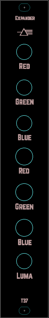
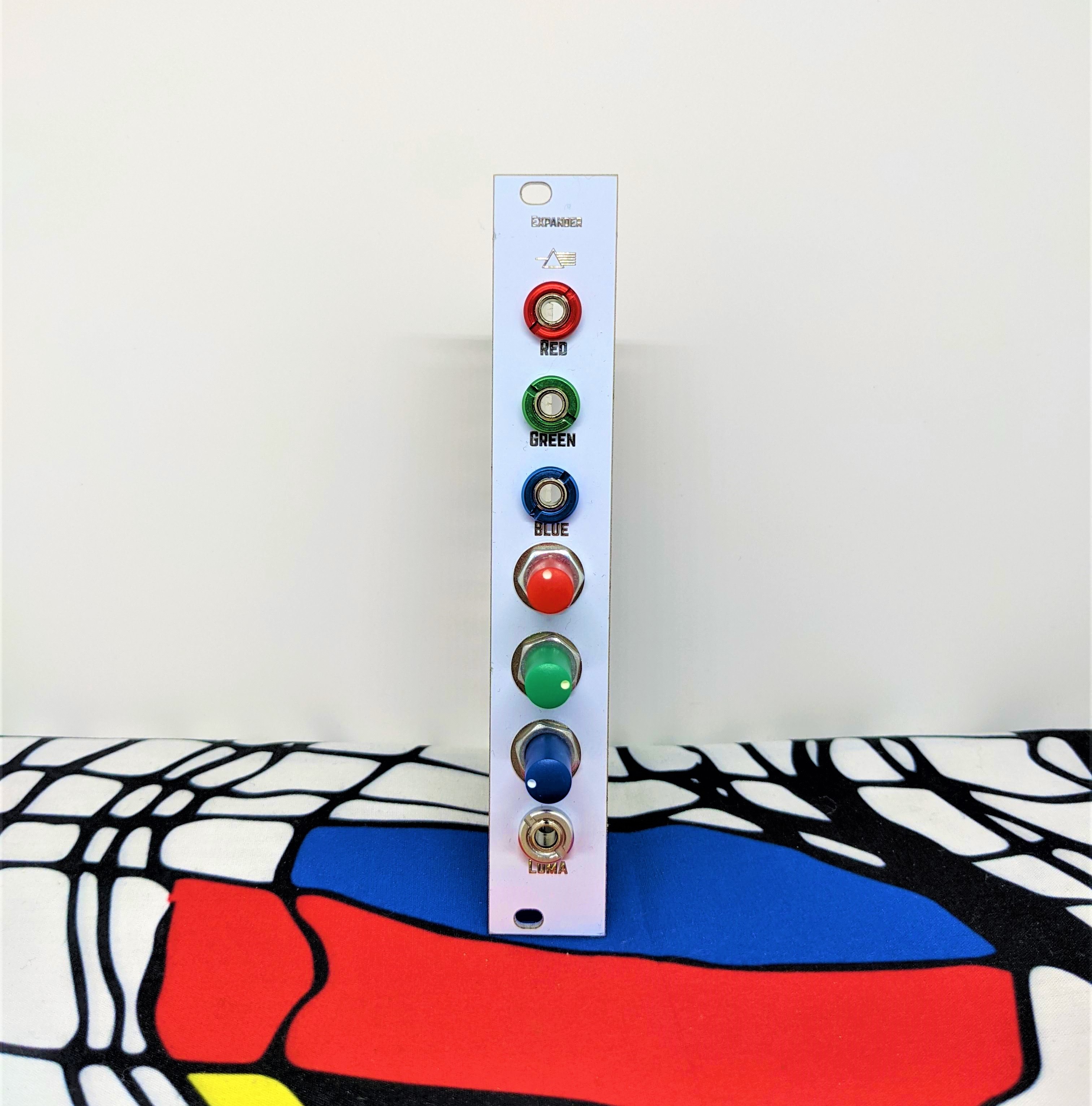
Visual Cortex pre-encoder expander
Category: Unknown · Tags: memorypalace, visualcortex · Posts: 137
#1 — luix · 2018-09-06
Soooooooooooooooo I’ve ordered a MemoryPalace and was thinking on how my workflow could be with it! And to be honest I would love to use the MP as final stage + encoder because of the HDMI outputs…
The problem if I do it this way, I won’t be able to use my Visual Cortex’s mixing+keying section (which I love and use a lot) , because cortex don’t have RGB LZX lvl outputs, so I can only use it as encoder final mixer… unless
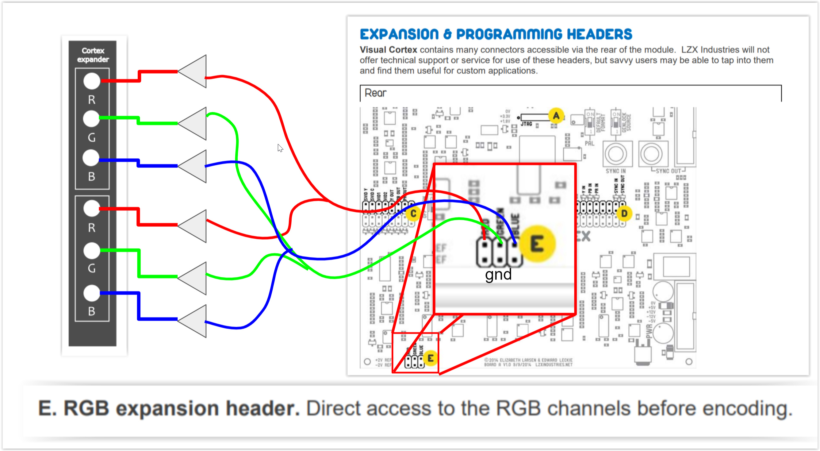
I want to use the hidden treasures of the Cortex, pre-encoder expanders. So my plan is to build a small PCB of maybe 2hp or 4hp, that has the pre-encoder outputs of the mixer as a double buffered outputs (will be using those 6172 @pbalj that we purchased)
I wanted to share the idea to double check how feasible is, but also to know if any of you find it interesting, or if I’m missing something or a mistake).
With this expander, I can use VC super duper mixing capabilities and send it to the MP inputs!
#2 — luix · 2018-09-06
of course I would have to add 2 cables one 2x3 ribbon for the encoder output, and europower 2x5.
@pbalj maybe its a good idea for you 1u tiles
#3 — Dewb · 2019-01-25
@luix did you end up building this? Has anyone else considered it? I might give it a shot this weekend (one set of outputs, without buffers, to start.)
#4 — northerntao · 2019-01-27
For some reason, I thought the MP had a composite input, but I was sorely mistaken.
I’m not really a DIY guy, but I’d be willing to chip some $ in for the cause. This looks fairly simple though, so if it was a simple PCB, my shakey hands could probably solder it.
I have a composite to component adapter that has an RGB option, but I doubt it will work without some sort of attenuation to the 1v spec.
#5 — reverselandfill · 2019-01-27
something like this? please correct any mistakes!
I’ve made 3 outputs now. Easy to double up if that is needed.
Maybe the buffers should be without resistors.? - pic2
(still a beginner)

or

#6 — luix · 2019-01-27
Sorry for the super late response… I’ve been sick and bed the last week and couldn’t post anything.
The answering all of you, YES, I have a pcb design for this. Back in november I worked a bit on the breadboard and the crossed some conclussions with Lars on how to do this in the most interesting way.
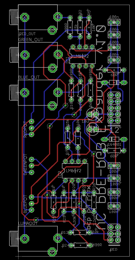
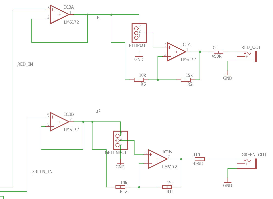
The first approach was as @reverselandfill said just to use buffers, but Lars suggested to add attenuverters in the outputs to be able to invert the output signal of the cortex, also a LUMA OUT is super handy specially to patch in the alpha channel of the Memory Palace, here are some pics.
Here is the schematic, I’ll release the files on github once they are tested and working… It will be really bad if some VC die because of my fault

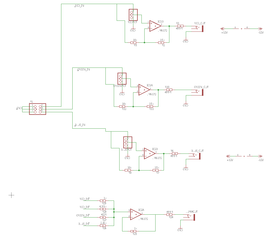
Anyway, I’ll be building and testing these pcbs next week so expect some news soon!
#7 — luix · 2019-01-27
On the second schematic you made, the R4, R10 and R14 are not needed. I made almost the same design and Lars said those resistors are not needed but the signals come from a known world (impedance, levels, etc…) the pins could go directly in the non-inverting inputs of the op-amps.
#8 — reverselandfill · 2019-01-27
Yeah, I thought that already.
But good news with the progress. I’ll leave it to you then !
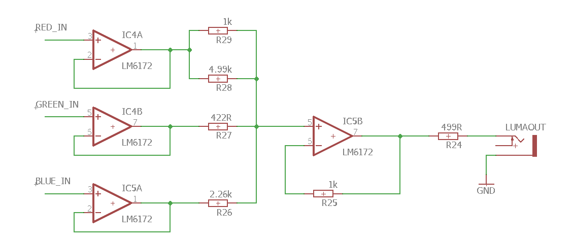
Where did the luma come from? is that a summed signal ?
#9 — luix · 2019-01-27
Yes! Lars shared how to extract Lumma from RGB, using those magic weird value resistors.
#10 — reverselandfill · 2019-01-27
aha magic. that was what I thought. I’ll check the schematic then

#11 — Dewb · 2019-01-28
Fantastic news, thank you! I was just thinking that a luma output would be a great use for the fourth op amp channel.
#12 — creatorlars · 2019-01-31
RGB to Luma is very handy (and a cheap addition!) Someone should do YUV to RGB and RGB to YUV boards at some point. If you had UV, you could patch up a chroma keyer with some Castle logic and some C8s!
#13 — creatorlars · 2019-01-31
For reference
From RGB to YUV
Y = 0.299R + 0.587G + 0.114B
U = 0.492 (B-Y)
V = 0.877 (R-Y)
It can also be represented as:
Y = 0.299R + 0.587G + 0.114B
U = -0.147R - 0.289G + 0.436B
V = 0.615R - 0.515G - 0.100B
From YUV to RGB
R = Y + 1.140V
G = Y - 0.395U - 0.581V
B = Y + 2.032U
#14 — luix · 2019-03-25
So I finally pulled some time to build and test this pcbs, and the mixer section works pretty well… The problem I’m seeing is with the Lumma. I need to do further testing of the circuit.
For some reason when I put a signal into R it pops in all the other channels, the same happens for G and B, but there are not short or overlapped traces anywhere so Im guessing Im not testing it right.
I added some fast diodes to prevent voltage return to the mixer section on the Lumma resistors but its not working… maybe I need to connect all the three channels.


Anyway just a heads up on this. The schematic is already posted on this thread.
#15 — pbalj · 2019-03-26
I need one of these for use with memory palace!
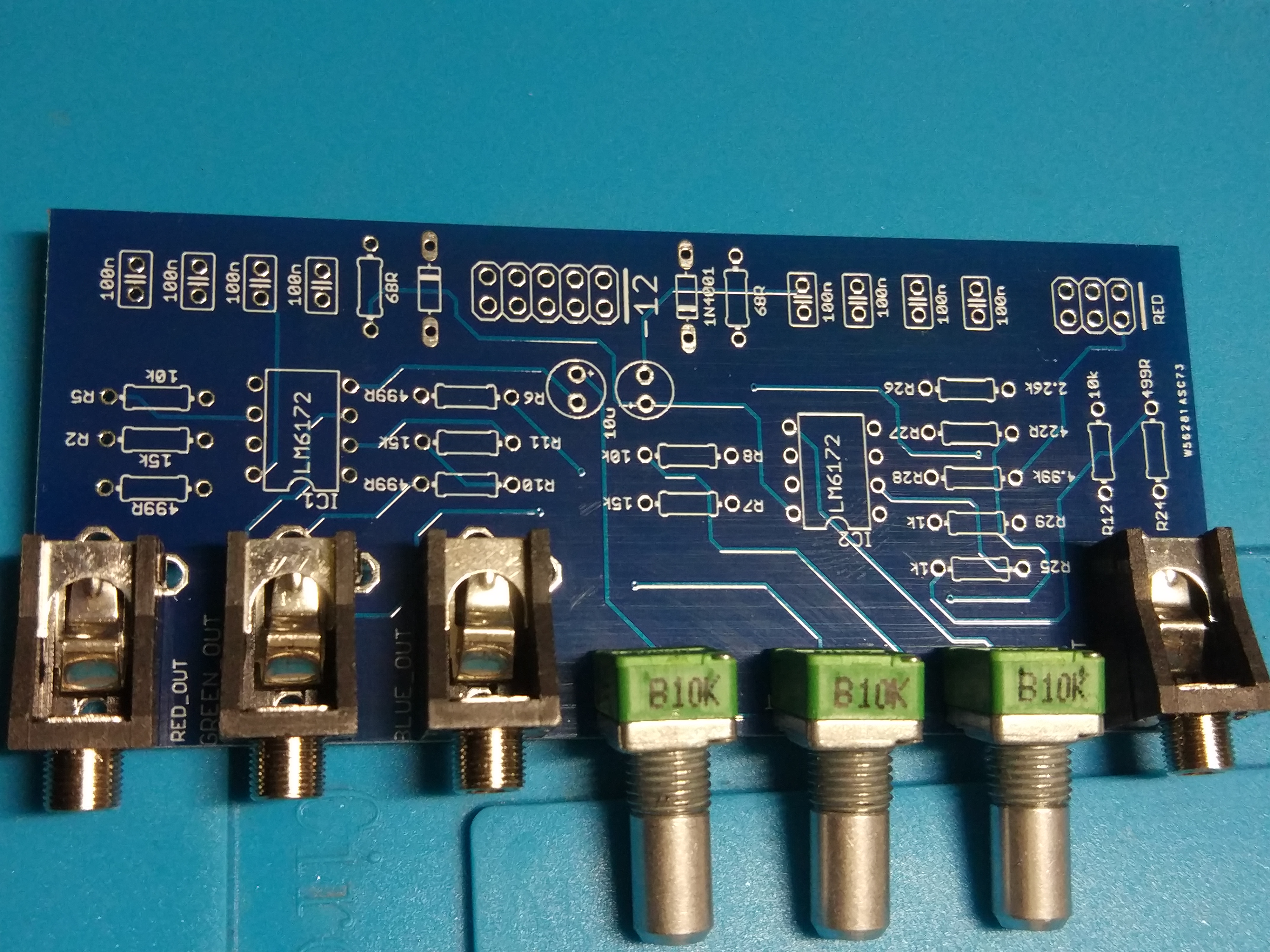
On the pcb, though, the 100nf decoupling caps should be as close to the power pins of the ICs as possible.
#16 — luix · 2019-03-26
you are correct sir, thanks.
#17 — creatorlars · 2019-03-26
I think you may need to buffer the RGB inputs before putting them thru attenuverters, etc Can you probe what you’re seeing at the input nodes on the scope?
#18 — luix · 2019-03-28
Apparently the problem was that I was testing with only one channel (R or G or B) at any given time, and the rest of the pins were “flying”. So the Luma resistors “mixer” made the signal comback from the other chanels the one connected/testing. This is not an ideal way of testing since all the time the VC will be connected and either send 0v-01v on each channel preventing this bleed.
I’ll add buffers to the inputs of the lumma and the before the attenuverters. If I only add buffers to the Attenuverters I will still get bleed from the Luma resistors-mixers. If I only add buffers to the 3 Lumma inputs I could get attenuverted signal from the feedback of path of each attenuverter.
So far the solution I like the most is to connect hte Lumma to the outputs of thf buffers RGB, that way there is no way to get it wrong. The only problem is that Lumma can get “dirty” if any cables with dirty signals (stacked) are plugged into the outputs of the expander.
#19 — luix · 2019-04-01
Updates!
So I’ve worked a bit during the weekend on the pcb, now I moved all the 104 caps near the power pins of the 6172 as suggested by @pbalj, also added buffers to everything… I wanted to make this board very cheap thats was why I tried to save on ICs, but it doesn’t make sense to save up money just for 2 more 6172.
I’ll fab boards and panels and post back any news.
When the time comes and everything is finished, I’ll publish the eagle and gerber files probably in my github so anyone can fab it, in any case I’ll have spares that can sell… but was wondering if anyone is interested in kits maybe I can put together maybe 10 or so. If not I’ll only sell the pcb+panel set for like 10€ or 15€ depending on the cost of the aluminium panel :). Let me know your interest with for either pcbsets or kits?
#20 — wednesdayayay · 2019-04-01
I’d be in for the most complete version possible (no DIY skills here)!
love this project
#21 — Agawell · 2019-04-01
I’d like a pcb/panel set please!!!
@wednesdayayay - watch a couple of basic videos on how to solder and then check out diy synth guy on youtube!
get a really basic soldering iron and a cheap kit to practice with (mults or something) - it’s really quite easy - I learnt last september and have built 20 modules - including 5 cadet and 6 castle modules and 3 smd (2 ripples and a buffered mult) virtually everything worked first or second time - one of the ripples is not quite right - but otherwise all ok
#22 — northerntao · 2019-04-01
I’m interested in the kit if possible, but a pcb+panel would be appreciated as well. Thanks!
#23 — tenshun · 2019-04-01
count me in for a Kit if possible as well!
#24 — destroythings · 2019-04-01
I would take a pre-built or kit.
#25 — brendanleespengler · 2019-04-01
I’d be down for a prebuilt module!
#26 — csboling · 2019-04-01
I’d take a PCB + panel too, love the mock up :]
#28 — luix · 2019-04-01
I could do a built module won’t be difficult, but keep in mind that you will need to mod your Visual Cortex, which is solder a 2x3 pin header.
Its not difficult but you will need to do it your self (or find someone close to you)
#29 — luix · 2019-04-01


#30 — destroythings · 2019-04-01
Yeah I’d be down for a prebuilt, Sure I could figure out fitting the header.
#31 — brendanleespengler · 2019-04-01
Hey, could a little header kit be sold w the modules? That would make things so easy!
#32 — luix · 2019-04-01
the full kit im planning will have pcb panel, pots, knobs, jacks, components (ics, resistors caps etc) a 3x2 header for cortex and a ribbon cable for the rgb expander header.
#33 — luix · 2019-04-06
@creatorlars Im gonna do a second flavor of the expansion with YUV outs. Was wondering if I can use the Lumma circuit that you kindly show me as the Y

or I must do another new lumma signal (I was going to go with voltage dividers of R G and B)
Y = 0.299R + 0.587G + 0.114B
My real question is if the Lumma of the YUV is different to the Luma schematic. Luma YUV vs Luma RGB (I would say no, but I’m in doubt.).
This lumma circuit is magix!
#34 — 337is · 2019-04-06
Great work on this @luix! I’m down for two kits. Curious as you’re planning a second breakout … could they easily be combined into one expander?
#35 — luix · 2019-04-06
yeah should be easy to chain them.
#36 — creatorlars · 2019-04-06
@luix That circuit should work fine! For the U and V outputs you can follow a similar method. I generally use SPICE simulations to tweak circuits like this until output voltage readings are correct according to RGB input voltages. 5Spice has a free version we’ve used for years, although I’m using Tina more frequently now.
#37 — wiatrob · 2019-04-08
I’d be down for a kit to support the project. My cortex already has expansion headers soldered
#38 — Resonant_Space · 2019-04-08
I’ll probably want a PCB+panel at least. Wasn’t planning on getting a visual cortex, but I’ve run into a dead end trying to troubleshoot my cadet sync generator build–so I should probably just buy a vc.
#39 — giantmecha · 2019-04-10
Sign me up for one too!
I’ve been running the VC component output back into its Input Decoder, and then out from those 1v RGB outputs into the MemPal. Not so ideal, of course, as I lose that component input. :-/
#40 — bsarps · 2019-04-11
I’d like to get a kit or prebuilt as well. This is a great project, thanks!
#41 — aaronsbrown · 2019-04-11
Def. in for a panel/pcb when you are ready to take orders
#42 — Genlok · 2019-04-12
I am in for this! Would take a kit, or panel/PCB, or built version.
#43 — otoskope · 2019-05-03
I’d be interested in panel+pcb or kit! YUV version would be great too - any chance to combine them, or will they be separate exapnders?
#44 — wednesdayayay · 2019-05-03
right! I would absolutely go for the dual if it was an option
#45 — luix · 2019-05-06
I started to lay the PCB for the YUV version, but decide to first finish this run of pcbs test them, prepare kits, and a solder prebuilt modules and then will do the YUV.
Both will be compatible and can be used at the same time since they read from the RGB expansion bus of the Visual Cortex
#46 — otoskope · 2019-05-06
Sounds absolutely reasonable. I am definitely still interested also in a single RGB version!
#47 — luix · 2019-05-06
I’ve just got home and the postman had a surprise, and I remembered a quote from a famous American movie:
Life is like a box of pcbs and panels, you never know what your gonna get.>>>> -Forest Gump

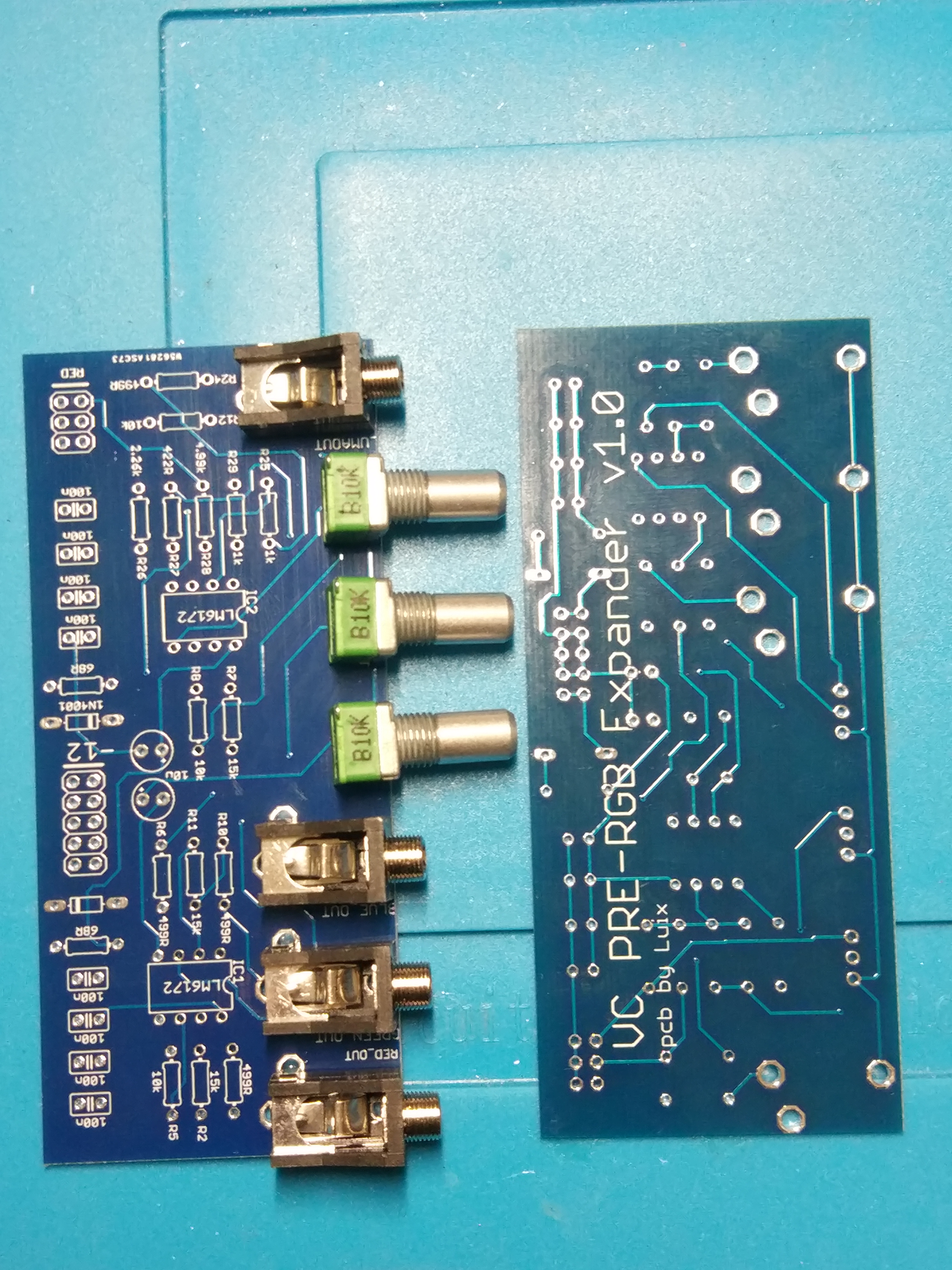
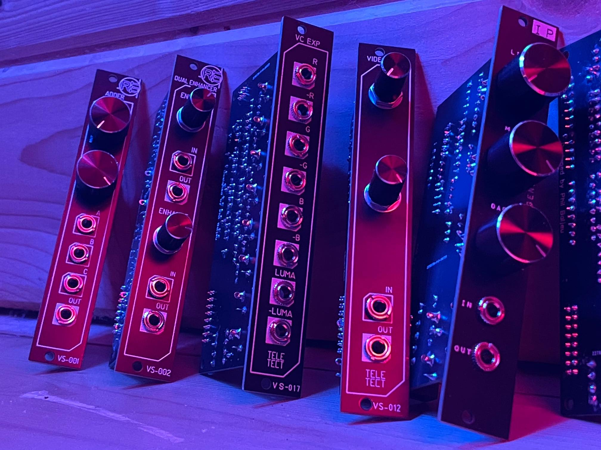
So final version pcbs (will double check them again everything is fine) and PANELS arrived.

This red panels are in honor to all LZX Cadets 

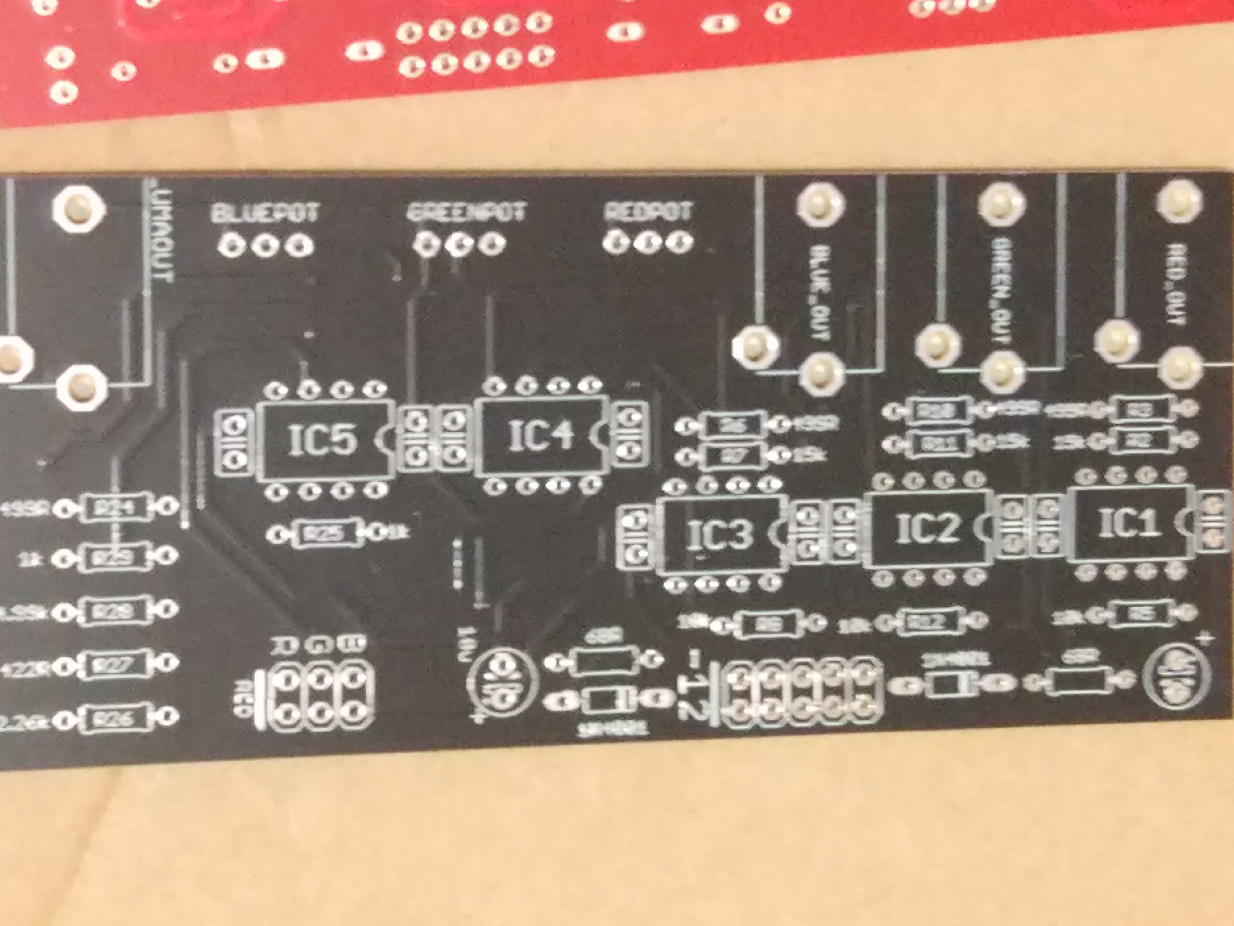
@pbalj now caps are nicely placed, thanks for the suggestion I completely forgot about it.


Panels fit perfect on previous pcb (which is same footprint as the new one) there will be 2mm Red PCBPanel and 2mm Black aluminium panels. I don’t know if I should give the option to chose or just include both on every kit…
I still need to get to details to costs on kits and built modules, but will probably target at 50€-60€ for kits and 70€-90€ for built modules (plus shipping from Spain probably 6€-15€ depending if you are EMEA or Mericaaa). After all kits are sold I’ll sell spare pcbs :).
So my next steps will be to check everything is fine with the pcb, if so I’ll probably send a Google Form in this thread so all of you can write which ones and how many kits/modules you will want.
After the form is closed I’ll be able make the order of the parts to Mouser (so 3 days) and then I’ll ask you within those days to send me a PayPal.
Ill keep you all informed, I’m very excited on this project because its a community project for the LZX community.

#48 — luix · 2019-05-28
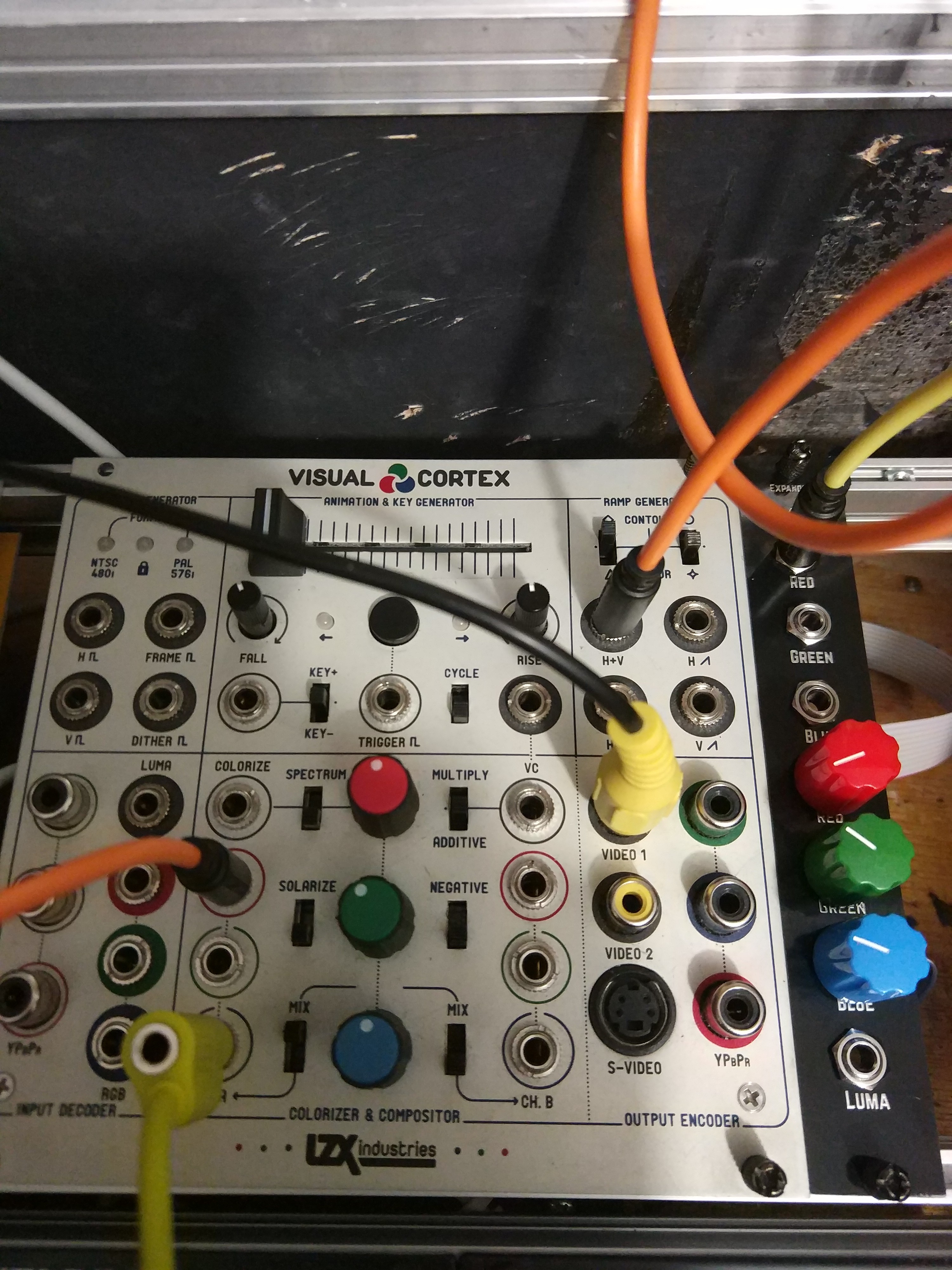
Updates on this, the board works as expexted, it as two minor bugs I’ll fix for the final version (pots are inverted, so positive signal should be from 12’ to 5’ (clockwise) and inverted signal from 12’ to 7’ (counterclockwise), second bug is that the color pins are swaped so Red is Blue and Blue is Red. in the video you can see how I patch a V ramp to the Byle and output that on the expander Red’s output.
One thing I wanted to ask on this thread for all your consideration and feedback is the following. When the attenuverter inverts the signal which is 0v to 1v DC from VC it outputs a 0v to -1 (inverted duh)… but the standard video signal is always 0v to 1v, so the inverted signal is not super usefull unless you use the AC switches or you invert it back or add a offset of 1v.
My question is, does it make sense and is useful for you to have an inverted (-1v) signal? Or should I replace the attenuverter with a attenuator (just attenuate from 0v to 1v and not invert). I’m scratching my head on which use case would be more useful for most ppl. I think there are use cases for both but what the vidiots think?
Maybe the best solution is to add 1v to the inveted signal, so its always 1V regardless if its inverted or not?
I’m asking all this for the first time when I actually plugged it and started to use it on different parts of my system.
#49 — Resonant_Space · 2019-05-29
It might be handy to have the inverted signal available for summing with a positive voltage. I don’t see much downside to using an attenuverter.
#50 — stefangoodchild · 2019-06-20
I’m def up for a kit or prebuilt, whichever. Ideally pre-built
Really excited to combine the Cortex and MP like this. Thanks for your hard work!
#51 — efp3 · 2019-06-24
I would be down with a prebuilt for sure!
#53 — Genlok · 2019-07-17
Also in for prebuilt versions of both expanders when they’re available.
#54 — luix · 2019-07-19
So I’ve been busy with another thing the last couple 2 weeks, but I think I will be able to finish the expander project in July. The current status is its a working version but with some noise, so I need to investigate whats the problem with the board.
This project wont get abandoned
, anyway @pbalj told me he wanted to design/build/sell(?) another version of the expander he is probably working on so we may have 2 flavor of this expander soon!
#55 — wednesdayayay · 2019-07-19
I’m still very interested in a prebuilt unit!
at the same time
I like flavors
haha
I’m sure I’ll end up with a second visual cortex at some point that way I can do one of both
#56 — Genlok · 2019-07-19
Ha! I am in the same boat. I am definitely getting a second VC in the future.
#57 — Nathan · 2019-07-23
Im down for a prebuilt.
#58 — petro · 2019-07-24
I am keen to order a pcb/ panel if possible , thanks
#59 — Bhut · 2019-07-24
I´m also interested in an prebuilt one!!
greetings from sunny Bielefeld/Germany
#60 — petro · 2019-09-13
Any news on this ? @pbalj ? I am interested in diy PCBs / or built modules for an output expander for visual cortex
#61 — Resonant_Space · 2019-09-15
Every time I patch my system, I miss this module. Wish I could help in some way, but I know very little about circuit design.
#62 — petro · 2019-09-15
@creatorlars this could be a good idea for a new cadet module (diy pcb /panel), I feel like if more VC users knew what this does, it could be really popular
#63 — luix · 2019-09-15
I’m happy to announce that the cortex expander is finally ready for production. I’ll post a vid later this week and all the details to order. Sorry for the big delays on this, but there were lots of things happening in my life lately but I’m back.
The plan is more less the following:
this week: I’ll send to fab the final pcb to China.
22-29/09 I’ll announce final cost and estimated shipping, a google form will be available to specify what you want. On 29 I’ll close the form and order components to the part supplier.
29/09 to 06/10 a friend and I’ll be soldering and building the prebuilt orders.
shipping is expected as soon each module is finished and tested, so first come first serve.
I’ll ship PCB+Panel only kits as soon the prebuilt modules shipping starts. I’m expecting this module to be very cheap hopefully. Anyway here is a link to a page we with some audio eurorack modules we have designed on the last years for local workshops in Madrid.
#64 — northerntao · 2019-09-15
Hell yes. Thanks!!!
#65 — wednesdayayay · 2019-09-15
oh this is awesome
so if we do get a prebuilt unit this will still require us to solder onto the visual cortex itself right?
#66 — northerntao · 2019-09-15
Is that 4hp or 6hp? I’m in the middle of rearranging my cases, so I’ll leave some room for it.
#69 — Resonant_Space · 2019-09-15
The RGB pads on the Visual Cortex don’t have a header in place for a connector, so a tiny bit of soldering will be necessary.
#70 — luix · 2019-09-16
northerntao wrote:
Is that 4hp or 6hp? I’m in the middle of rearranging my cases, so I’ll leave some room for it.
4hp, like a cadet/castle
#71 — luix · 2019-09-16
Yeah I does, there is no other way as the VC does not come with pins on those pads as stated before. I’ll show later on before anyone places an order what you will need to do, just to make sure you know what you are getting into.
Its actually pretty easy, but you will need a good soldering iron, since the PCB of the VC has a superb thermal design and its difficult to heat everything.
#72 — wednesdayayay · 2019-09-16
I’ve done very very minimal soldering like point to point to make passive boxes (switches, photoresistors, pots etc…)
but after looking at the back of the visual cortex I think it is something I could handle
I am very much looking forward to this being available
#73 — Agawell · 2019-09-16
if you can solder a wire to a pot then you can do this!!!
it’s as simple as sticking the header in the holes and then applying heat and solder - watch a youtube video first on the basics of pcb soldering and you’ll be good to go!!
I think the hardest part will be removing the panel and reattaching it!
#75 — luix · 2019-09-16
It will be included, also all the cables and everything needed except the soldering iron and some solder and patience
#76 — wednesdayayay · 2019-09-16
that is so rad! this is going to make for some very fun video synthing
#77 — mattzog · 2019-09-19
I’d like to get in on this for a board and panel.
I already soldered pins on to my corrtex and made an output expander to send RGB to the MemPal, but it’s not buffered at all, and your better solution is appealing.
#78 — wiatrob · 2019-09-20
Save two for me if I don’t respond immediately, it’s a busy time
#80 — luix · 2019-09-23
It works exactly like that.
The luma is unaffected by the RGB knobs and goes out directly.
The RGB goes to a bit higher than 1v when the knobs are fully clockwise, and -1v when it goes counterclockwise.
On the middle (12’ clock) the gain is 0 and the channel will not pass thru. Hope that makes sense.
#81 — luix · 2019-09-23
UPDATE! The pcbs are been fabbed now in china
Tomorrow I’ll record a vid on the module and publish the costs and form to reserve a module. I’m planning on doing a 30 built run, and 30 pcb set, with some spares
#82 — luix · 2019-09-25
Here is a vid I recorded to try to clear what I think is important.
TBH the only thing I dont like about this module is that potentiometers are too tight (close) so I sacrified some ergonomics in favor of having luma outs plus as-much-as-possible skiff friendly module.
#83 — Resonant_Space · 2019-09-25
It looks awesome! Ready to order

#85 — wiatrob · 2019-09-26
Nice video and great work @luix!
#86 — petro · 2019-09-26
@luix How do I order one diy panel and pcb. Thanks


Please DM me for payment
#87 — petro · 2019-09-26
IDGI why it needs 5x lm6172 ? Don’t they 2 channel on each chip
#88 — joem · 2019-09-29
You have to buffer each input (3), each output (4), so you’re looking at 7 opamps minimum, or 4 LM6172’s. I guess you also need some for the luma mixer, too?
#89 — wiatrob · 2019-09-29
@joem is correct, the signals need gain in this case so they need to be amplified as well. I breadboarded a single channel similar circuit few years back and it would have used 6 LM6172’s (my memory’s hazy - no input buffer, inverting amp and inverting output buffer I think).
#90 — luix · 2019-10-02
More updates on this, PCB from factory came and I built it.
I’m noticing some bleed noise on channels when doing the “hard edge” test that Lars always recommend to detect bleed, otherwise the board is good to go. I wrote to Lars and Phil to see if anything can be done to remove/reduce this.
This means maybe two more weeks of delays so you all start ordering yours. I don’t want to ship you a board that has some noise (even if is small) and I’ll end up refunding paying stuff so just want to be super honest and clear with what you will be getting… I will record a clip explain this hard edge test, and showing the bleed so you all know a little bit more on how you should test your video equipment/modules.
#91 — wiatrob · 2019-10-03
What’s a little noise on a hard edge!
Standing by, @luix…
#92 — Grain · 2019-10-09
I feel a little stupid here, so please excuse the noob question!
Can anyone explain, simply, why I might want to do this with my Visual Cortex? I’ve read through the thread here, but I can’t get a grasp on what this upgrade might be used for, in practical terms?
#93 — wednesdayayay · 2019-10-09
this gives your visual cortex LZX standard 1/8 outputs of whatever is coming out at the composite/svid/component outs
RGB and LUMA
this could be used for feedback, further processing connecting to another system lots of fun stuff!
#94 — Genlok · 2019-10-10
So we’re not placing orders yet right? Don’t want to miss this when it’s time!
#95 — luix · 2019-10-11
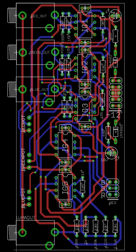
Im waiting for final PCBS with ground plane to reduce bleed noise, they have been manufactured and their are on their way to me so should be receiving them next week probably.
#96 — tylerm · 2019-11-04
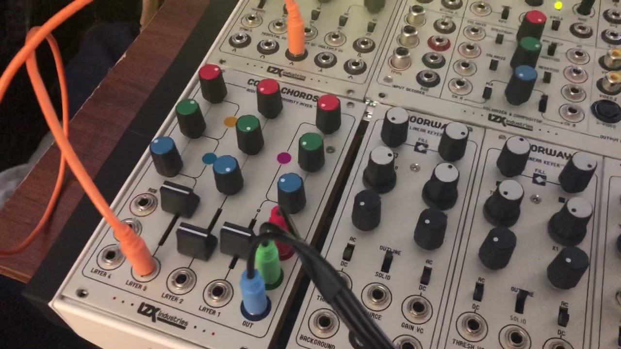
One use case would be if you have another module with its own set of video outputs and you want to feed it a signal that’s mixing both of the Visual Cortex’s compositing channels together. Some LZX modules have RGB 1v outs (Color Chords, Marble Index, Mapper, Memory Palace), just as the Visual Cortex has two sets of RGB ins in its compositing section.
However, the only way you could get full RGB (or the functional equivalent, at least) out of a Visual Cortex without any sort of expansion attached is via the component outputs. BUT, in order to put this back into another part of the LZX system, it would need to be decoded again via another Visual Cortex input decoder section or a TBC module, as it is now a valid video signal instead of the LZX 1v standard. This expansion panel serves as a much less cluttered way to continue processing a fully patched Visual Cortex, or to take advantage of final output via another module (such as the DVI/HDMI output of the Memory Palace).
Did that help?

#97 — Grain · 2019-11-05
Thanks Tylerm, that’s very clear explanation.
I guess I’ll join the queue for this awesome upgrade!
#98 — Genlok · 2020-05-27
Finally got my expander installed and it’s working great! This thing kicks ass with memory palace
#99 — luix · 2020-05-27
Great to hear that enjoy it
#100 — wednesdayayay · 2020-05-27
yeah no turning back
it really made the chromagnon make more sense
that was I think one of the last straws for me before pre ordering (getting this up and running)
#101 — Genlok · 2020-05-27
It’s like have an entirely new flavor of feedback for memory palace. Wonderful!
#102 — Marizu · 2020-07-15
Thank you so much for this @luix it’s amazing!
I can’t believe that it’s taken me this long to get around to building it!
The only thing that I would advise is that if you use a shrouded, keyed header, then it will overhang the PCB a little bit. This makes it a little bit to fat to fit between Doepfer type rails. I desoldered it and put a pin header on, instead.
As you mentioned, the PCB ground plane makes desoldering difficult.
#103 — luix · 2020-07-15
Great news!!! so let me know if I can do anything for you or share any patch ideas
#104 — wednesdayayay · 2020-07-15
every time i used this expander it makes me more excited for chromagnon
things are going to get wild
is it normal that all my knobs are at about ~75% turned to pass through the regular colors?
I guess my expectation was that it would be at 50% but I could just be misunderstanding something
this has always been the case since I got it from you but I never really mess with the knobs so I forgot until the other day when I was re setting up my system
#105 — Genlok · 2020-07-15
Following this because I’m a bit unsure on that too!
#106 — luix · 2020-07-16
wednesdayayay wrote:
is it normal that all my knobs are at about ~75% turned to pass through the regular colors?>>>> I guess my expectation was that it would be at 50% but I could just be misunderstanding something
>>>
Yessss I specifically designed the circuits so they have about 120% gain when full clockwise or counterclockwise (inverted), I found I wanted to have extra “saturation” on my output signals sometime and that extra 20% worked fine. The downside of this is you will have to dial in the unity gain which has not been a problem for me really but well doesnt have to work for everytone as it works for me
12:00 > zero gain
3:00 > 100%
4:30 > 120%
9:00 > -100% (inverted)
7:30 > -120% (inverted)
#107 — bentoncbainbridge · 2020-07-17
Nice Expander, @luix! If one would forego the RGB pots, how hard would it be to just put the RGBY jacks right on a Visual Cortex, so as to save HP and keep my panels consistent looking?
#108 — luix · 2020-07-19
I dont think its possible the VisualCortex panel is full. Unless you do an extreme mod an desolder the RCAs for components out or the composite outs and then drill, or something like that but I really dont recommend you doing so…
#109 — bentoncbainbridge · 2020-07-19
Oh! That’s a good idea, @luix
If there’s a way to squeeze in a toggle switch, one could add RGB option to the component out RCA jacks.
Or, the same amount of panel real estate would fit a mini jack to accomodate a triple mini to RCA adapter http://tinkersphere.com/raspberry-pi-accessories/523-raspberry-pi-a-plus-b-plus-composite-to-rca-adapter.html
#110 — vhsdestroyer · 2020-08-09
Where can I order one of these?!
#111 — Agawell · 2020-08-09
try dm’ing luix - he may have some left - may only be a kit or a pcb/panel set though
#112 — luix · 2020-08-09
I checked today and I have 2 prebuilt and lots of pcbs so whatever you prefer.
#116 — Rik_bS · 2020-08-29
Hoping to buy one too, PM’d as well!
#117 — vhsdestroyer · 2020-09-09
Is there a website I can purchase through?
#118 — sigdigits · 2020-09-11
I’m interested in one of each of the PCBs!!!
#119 — dr_how · 2020-09-15
Are there any PCBs/kits still available? If so where can I order?
#120 — luix · 2020-12-14
Hi everyone!
I’m very sorry that I have not answered before any messages, but I was unaware of all of them for some reason I don’t get notifications on my email when someone PMs (I have to double check the notifications configuration on my account).
I still have pcb+panel sets if anyone is interested! Price is the same (in euros) please just note that snail mail to the US takes a lot of time now, some orders have taken probably 3 weeks and others almost 7-8 weeks but in the end all of them arrived safely.
If you want to get a set, just drop me a message to hadesbox at gmail dot com.
#121 — vhsdestroyer · 2020-12-14
Sick! Just emailed you
#122 — Jesse · 2020-12-14
I know @cinema.av (Evan Henry) was trying to get ahold of you - did y’all get in contact?
#123 — luix · 2020-12-14
Yeah I just answer him today, need to hear back from him
#124 — sean · 2020-12-18
Per the book of faces (which I look at approx. once a month or so), apparently @pbalj has a VC expander module.

#125 — wednesdayayay · 2020-12-18
a little different with no knobs but negative outs of everything included instead
so neat to see more stuff coming out from PB well not THAT PB…
#126 — Jesse · 2020-12-30
@wednesdayayay I see what you did there you ciat head
#127 — Tundra_Tides · 2021-02-18
Have messaged Luix, are you still shipping?
#128 — dr_pringle · 2021-02-19
would love one too if still possible

#129 — analogbrainsurgeon · 2021-02-23
Since some have asked about availability, Teleos Modular in Columbia, SC has one cortex expander left, last I checked. He has a reverb shop.
#130 — prakodr · 2021-02-23
Not anymore… Sorry (not sorry)
#131 — analogbrainsurgeon · 2021-02-24
Haha, nice, I got my order in before posting.
For those still interested, I noticed Teleos Modular listed more for sale today. I’m not affiliated with his shop, but I’ve picked up a few things from him and he’s a really cool guy. The build quality of the expander is excellent, technically and asthetically.
#132 — saiteron · 2021-03-27
thx for the ups
still have five built expanders available if anyone is interested & i can sell for $140 shipped in the US if bought direct instead of via Reverb. send me a message or email if you want one!
#133 — northerntao · 2021-04-10
VC expansion header install failed - that or the module is bad. Took my time, but having a heck of a time getting the contacts hot enough to get the solder flowing. Using a Hakko digital soldering station at 700F with Kester 245 63/37 no-clean solder.
On a brighter note, I modded my ER-301 Rev 7 so that it could talk I2C to my F8R faderbank. I thought that would be harder - had to solder a resistor lead to bypass an SMT diode. But the VC header is proving to be more difficult.
Repeat after me - You love to solder, you are a worthy, patient person who loves to solder. I don’t think the affirmation is working.

https://www.youtube.com/watch?v=-PhSU7MAwuw
#134 — joem · 2021-04-11
I don’t have any direct help with the actual issue, but when troubleshooting something like this, it’s a good idea to keep your signal chain as minimal as possible. Forget about the Color Chords for now. Instead test straight with “Prismatic Ray → Memory Palace” and “Prismatic Ray → Visual Cortext & Expander → Memory Palace” (and make the VC Expander → MP connection just be a single channel, not all three).
Doing that reduces the variables and reduces the likelihood of accidentally connecting something wrong or forgetting to connect something. (And makes it easier for other people to help you out for the same reasons.)
#135 — Fox · 2021-04-11
northerntao wrote:
VC expansion header install failed - that or the module is bad. Took my time, but having a heck of a time getting the contacts hot enough to get the solder flowing. Using a Hakko digital soldering station at 700F with Kester 245 63/37 no-clean solder.
Did you build the Expander yourself or did you just solder the 6 pin header to your VC?
I don’t have a VC but I’ve seen the drawing for the expander module. Maybe your 6-pin header is flipped 180 degrees. Three of the pins are RGB luma and three are ground so it is possible that luma and ground are all switched.
Lets have a look at your 6-pin ribbon cable between the VC and Expander.
#136 — northerntao · 2021-04-11
Yes, that is good advice. I was only using the Color Chords to demonstrate that the Memory Palace 1V RGB inputs were working, to rule the Memory Palace out as the issue.
The Visual Cortex does not have front panel 1V outs (like the Color Chords), but does have them on the circuit board. That’s what the 3rd party expander is for, though it requires the soldering of a header on the VC board for a ribbon cable to the expander.
But I can test one at a time, but even if one of them were working and the others weren’t, I would expect some change of output on the display.
I didn’t build the expander or the ribbon cable, but I did solder the header. My hunch is that is where the problem lies.
I can hook it up to a scope and see if there is output from each channel.
Thanks for your help!
#138 — northerntao · 2021-04-11
I bought the module prebuilt from the creator in one of the first batches over a year ago, but only got around to soldering the header this weekend when redoing my cases. He also provided the cable (and header)
I was careful to lineup the little triangle on the header with the R channel, so the indentation in the shrouded header is facing outward in this case.
I’ll pull it out again tomorrow and take a look at it and get some photos.
Thanks for your help!
#139 — luix · 2021-04-12
Hola @northerntao Josh, I’m very very sorry for the problems you are facing, its very weird but possible that the module I sent you is broken. I personally tested each “built” module for at least 30mins on my Cortex, precisely to avoid all these problems with all the people that got the expander. I wanted to avoid hassles to ship it back etc.
Anyway can you please take out the module and send some hires pictures to my mail hadesbox at gmail (or post them here for other future users, whatever you prefer) of solder joints on the expander header in the VCortex and also of the module (both sides) to see if there is any obvious soldering problem on the module?
If you want to ship the module back its also an option so I can check it out whatever you prefer.
#140 — luix · 2021-04-12
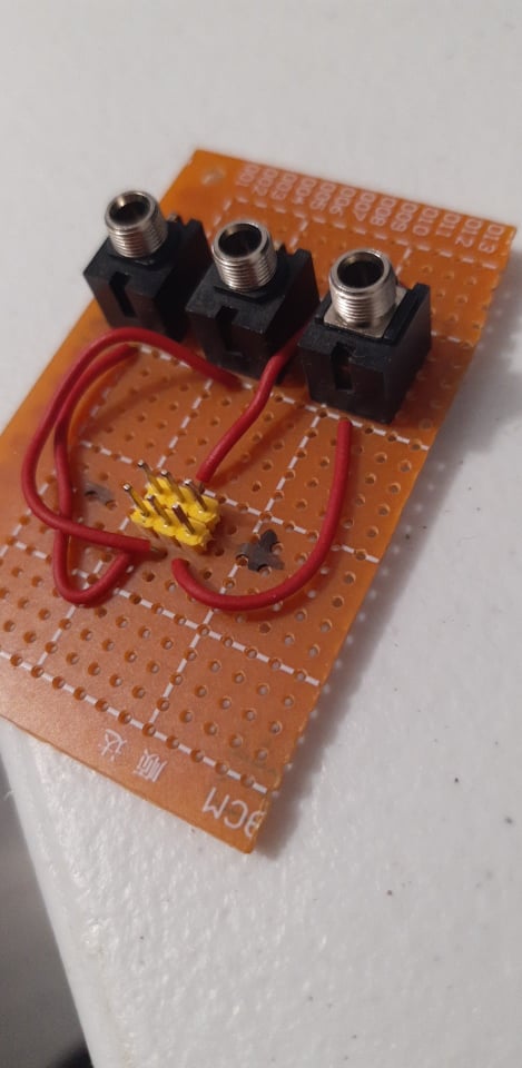
If you want to test the expander “standalone” without the cortex, and you can do simple soldering I recommend you building this board with 3 minijacks and a 3x2 header for testing the module. Its a super simple board that I built for testing each Expander before actually plugin it to my system, with it you can directly input 3 signals and test the three channel attenuations to discard if there is a problem with the module.
#141 — luix · 2021-04-12
I just remembered another user that had similar problems, and it was because I shipped him a “too short” cable and when he plugged the expander and put it back to its case, the header cable was unplugged by all the wiggling of the module during the module installation on his case.
The cable should be just enough to connect it, the very first cables I made were super short to avoid noise because the longer an unshielded cable, its more probable it becomes antenna for noise.
#143 — northerntao · 2021-04-16
Hey @luix! Thanks for the response! I’ve had a busy week with work and life so I haven’t had a chance to look at this again. Hopefully tonight.
The case its in is kinda cramped with cables so it may be the cable is loose. I’ll try that first. If not I’ll try removing and redoing the solder joints with a bit more heat on my iron. It took a lot longer than I’m used to to get the solder to melt.
#144 — northerntao · 2021-04-16
@luix - typing this on a phone and this forum editor hides the typing after a couple paragraphs.
So I’ll try that and maybe a different solder and flux. I’m using the no-clean Kester solder which has worked fine for me in the past, but I’m not a big DIYer.
If that doesn’t work I’ll let you know. I have some breadboard and various components laying around.
I know its been a long time since you shipped the module - I appreciate your help after all this time
#145 — niclal · 2021-12-16
@luix Hey Luix! By any chance, do you still got any VC Expander PCB + Panel available? I’m looking for one. Thanks!
#146 — Gavin · 2022-09-11
I have the kit, but not the 6-pin header for the back of the Visual Cortex. I keep buying headers but the pin spacing doesn’t match the points on the back of the Visual Cortex. What spacing am I looking for? 3mm? 2.54mm? 2mm? Maybe some LZX folks can advise.
#147 — Rik_bS · 2022-09-12
Here’s an extract from the BOM - quoting Mouser part numbers for 2.54mm spacing header
TypeValue/DescriptionQtyPart NumberNotesPin Header2x3 PIN HEADER2710-61200621621Expander connectorPin HeaderIDC 2x3 connector2649-71600-006LFribbon cable connector for expander
#148 — jwsmithwick1 · 2022-09-12
10 pcs. 2.54mm 2x3 Pin 6 Pin Straight Male Shrouded PCB Box Header IDC Socket Amazon.com
#149 — luix · 2022-09-14
Any standard 2.54mm double pin header should work, then you just strip it to 2x3.