[WIP] RAMPART - Dual Monostable / Pulse Generator
Category: Unknown · Tags: cadet, castle · Posts: 30
#1 — phosphenes · 2022-05-23
Hi All
A work in progress for you here. I’ve put together a schematic for a dual monostable generator. For those unfamiliar with monostables its effectively a one shot pulse generator. On receiving a positive edge on the input the output pulses high for a period of time defined by an RC circuit.
The plan is to squeeze it all into 4HP, with a potentiometer to control each monostable and a switch to change the timing ranges. Originally I started designing a NAND gate based monostable but the 74HC4538 IC is designed exactly for this function and gives the option of an inverted output without any additional circuitry. The inverting output allows more flexibility with using one monostable to trigger another, the plan is to use a jumper choose between a normal or inverted output on both circuits.
The supporting circuitry is based off of the Castle range so as always props to Phil for doing the leg work!
I feel like this fills a missing gap in the Castle range (Hence the name Rampart), but quite how useful this is remains to be seen.
Will hopefully get a panel and PCB drawn up, get this breadboarded and see what the video looks like. I’m hoping it might play well with the Differentiator! I still need to properly work out what the best RC values are to give the widest range. Any corrections, suggestions etc are much appreciated. Power circuitry is on another sheet but is very standard.
#2 — Fox · 2022-05-24
Cool idea, Ollie.
I think you need to two extra resistors: One on the negative pin of each comparator to divide the +5V down to +0.5V.
Or you could add a 0.5V reference to do the trick.
If I am understanding correctly, this will act as sort of an edge-detect; triggering a pulse (of controllable width) every time the input transitions from below the reference voltage. That being said, it may be worthwhile adding a pot to control the reference voltage from between 0V to 1V. That should give it more or less sensitivity when working with generally brighter or darker inputs.
If you were to try that out, I would definitely suggest adding a TL431 and TL072 with an extra pot.
I understand that 2xPots and 4xJacks pretty much fills a faceplate… I wonder how you’re going to fit those switches too.

#3 — phosphenes · 2022-05-24
Thanks Fox!
The negative pin is supposed to be tied to +0.5V (like the rest of the castle series, referenced by a TL431) - late night schematic design yields late night mistakes

Good idea on the reference pot, I was going for the module being in line with with the Castle series but I’ll experiment with the idea!
On spacing I think I can just squeeze 4 jacks, 2 pots and 2 switches into the 4HP, hopefully doesn’t impinge the ergonomics too much.
#4 — gzifcak · 2022-05-24
Awesome, I prototyped a similar thing once to get thin, sharp, white outlines on a black background. Very cool effect!
#5 — Rik_bS · 2022-05-25
I’ve used a fairly module-intensive patch to achieve similar (ramps > hard key > curtain), so a compact solution would be appealing
#6 — phosphenes · 2022-05-25
Good to know its been a useful function, will get a prototype together ASAP!
#7 — Fabong · 2022-05-25
Love it, a great, novel idea with a clear function. This is my favourite kind of module.
#8 — phosphenes · 2022-05-25
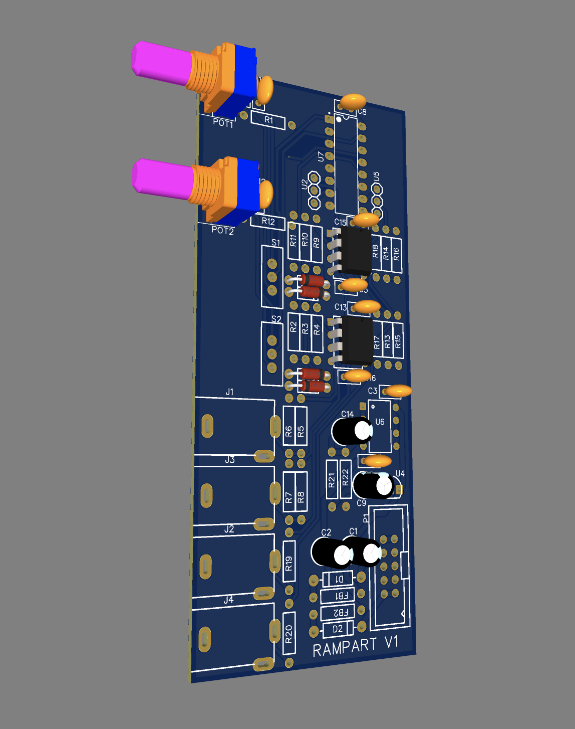
Made the changes suggested to the schematic. Here’s 3D model of PCB, apologies for not having all the components in 3D. Will do a proper design check tomorrow and look at getting a test batch ordered.
ap
#9 — Fox · 2022-05-25
R12 looks a little close to R11.
Care to share the final schematic for one last sanity check? DM is fine. I’m always online…
#10 — pbalj · 2022-05-25
RIP Rampart name. We had a module concept with that name

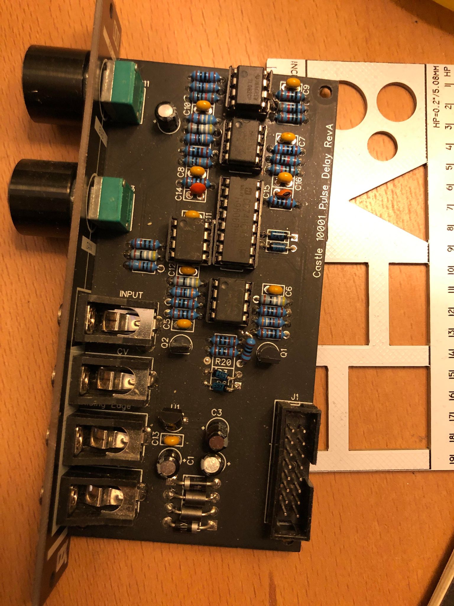
#11 — pbalj · 2022-05-25
and here is the pulse delay castle prototype, using the same 4538
#12 — Rik_bS · 2022-05-26
If that isn’t a strong endorsement for the concept then I don’t know what is…
#13 — phosphenes · 2022-05-26
Oh no! Happy to relinquish the Rampart name if you’d like, it was only a tongue in cheek reference to your Castle series anyway!
#14 — phosphenes · 2022-05-26
Oh yeah you’re completely right on R12

trying to squeeze designs in around work and play means I end up making these silly late night mistakes, I appreciate the sharper pair of eyes!
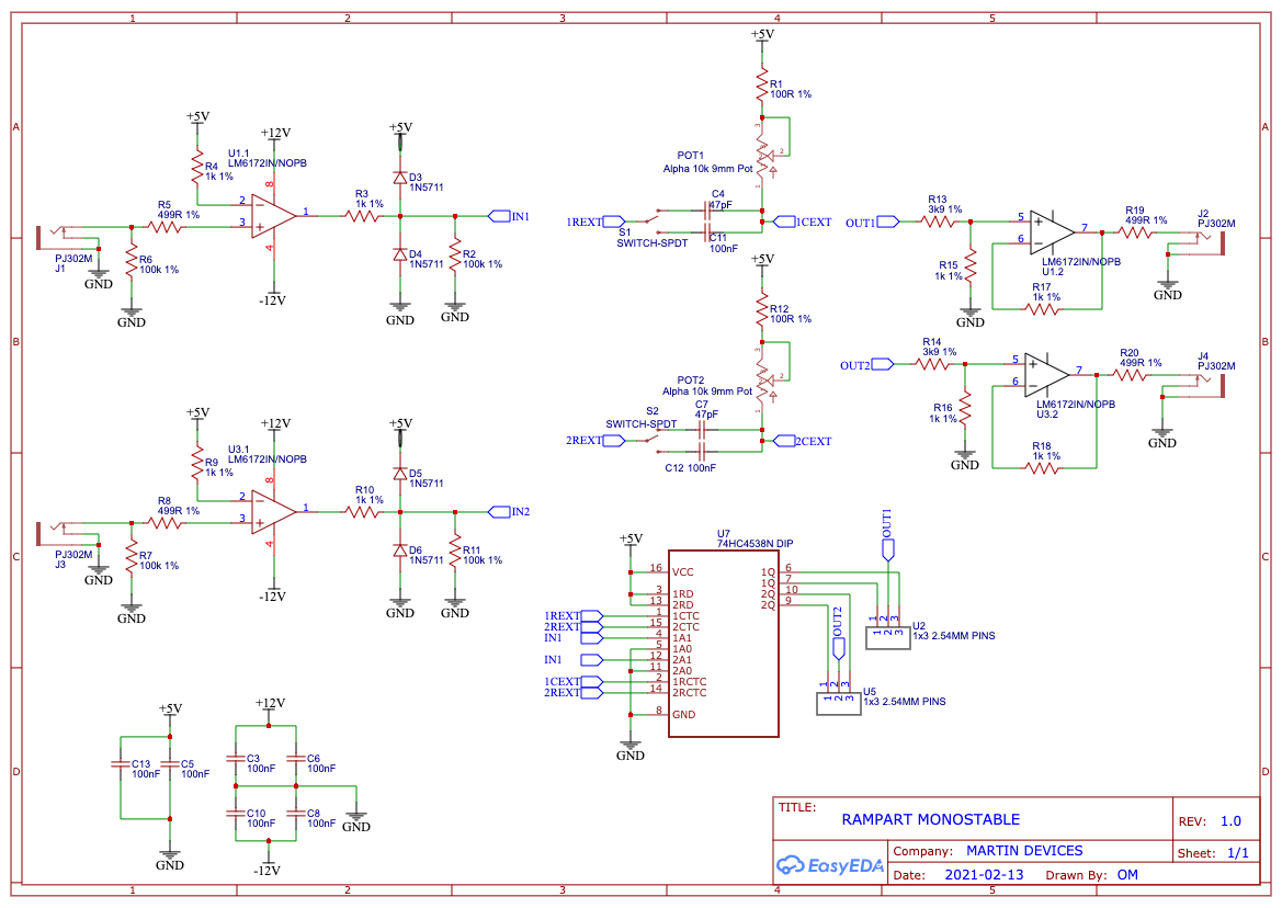
#15 — phosphenes · 2022-05-26
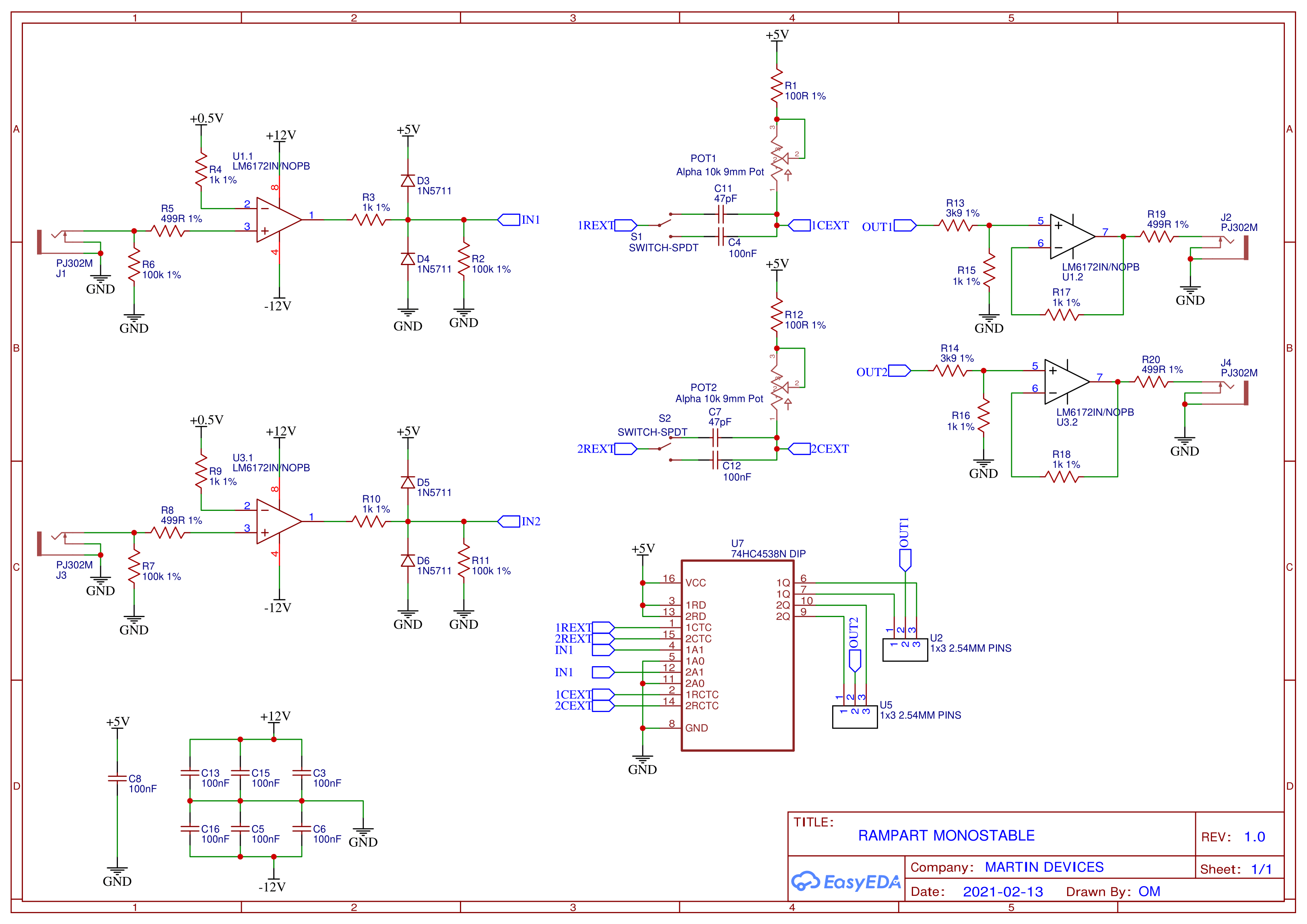
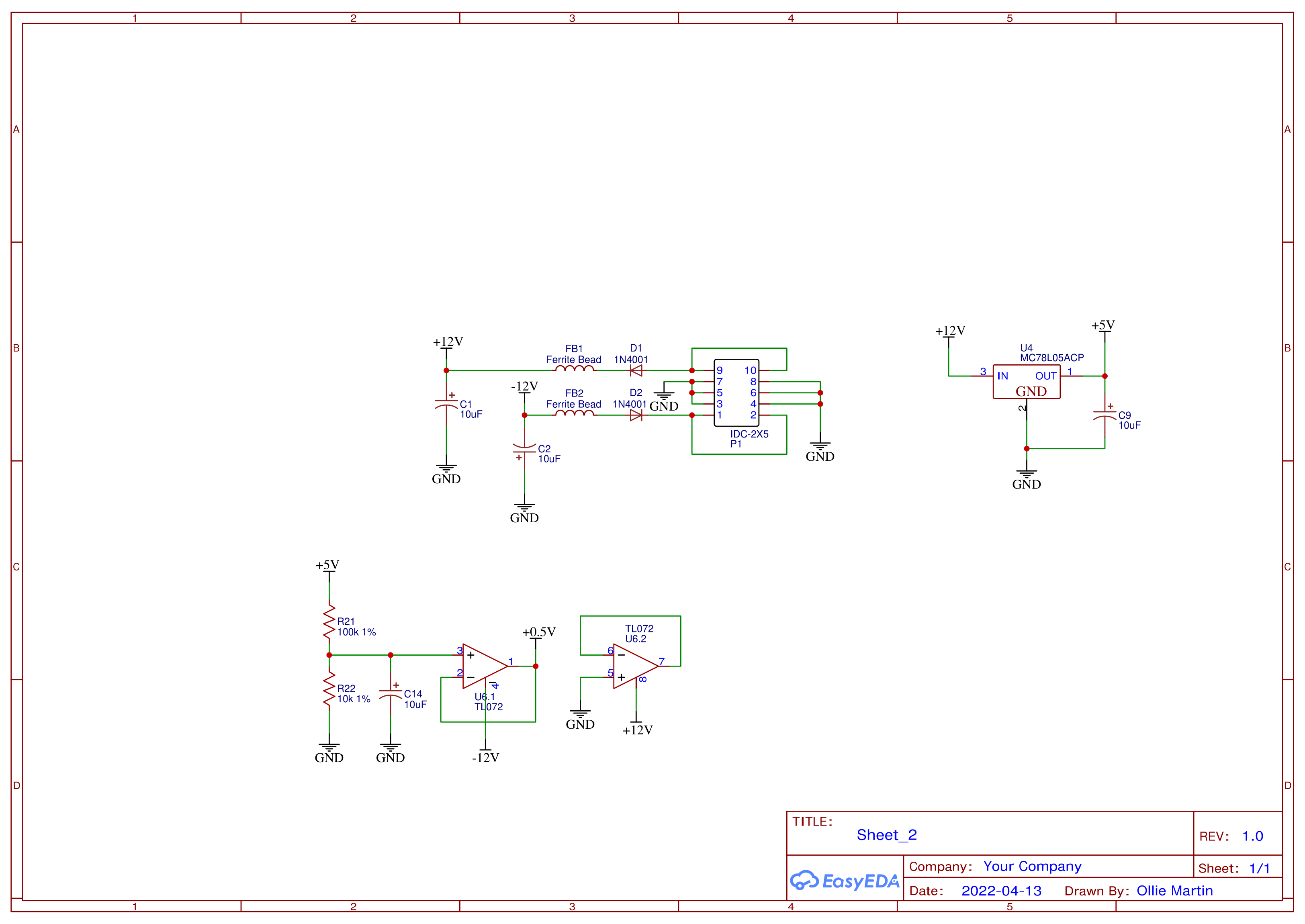
Here’s the updated schematics. I’ll clean up the component designators so they’re in a more sequential order, EasyEDA seems to struggle with them!
#16 — phosphenes · 2022-05-31
Small batch of prototype PCBs ordered from JLC. When they’re here I’ll get one built up and tested!
#17 — creatorlars · 2022-05-31
Great idea!
We had a prototype of our VCO once, that attempted a “one-shot” mode – it blanked the waveform after a single cycle, it was cool but needed further development.
Burst generator with decaying envelope as amplitude modulator would be a cool one to try too.
#18 — phosphenes · 2022-06-01
Thanks Lars!
A video rate envelope follower / slew generator is on my list. Synced to H or V could make some interesting ramp shapes!
#19 — phosphenes · 2022-06-16
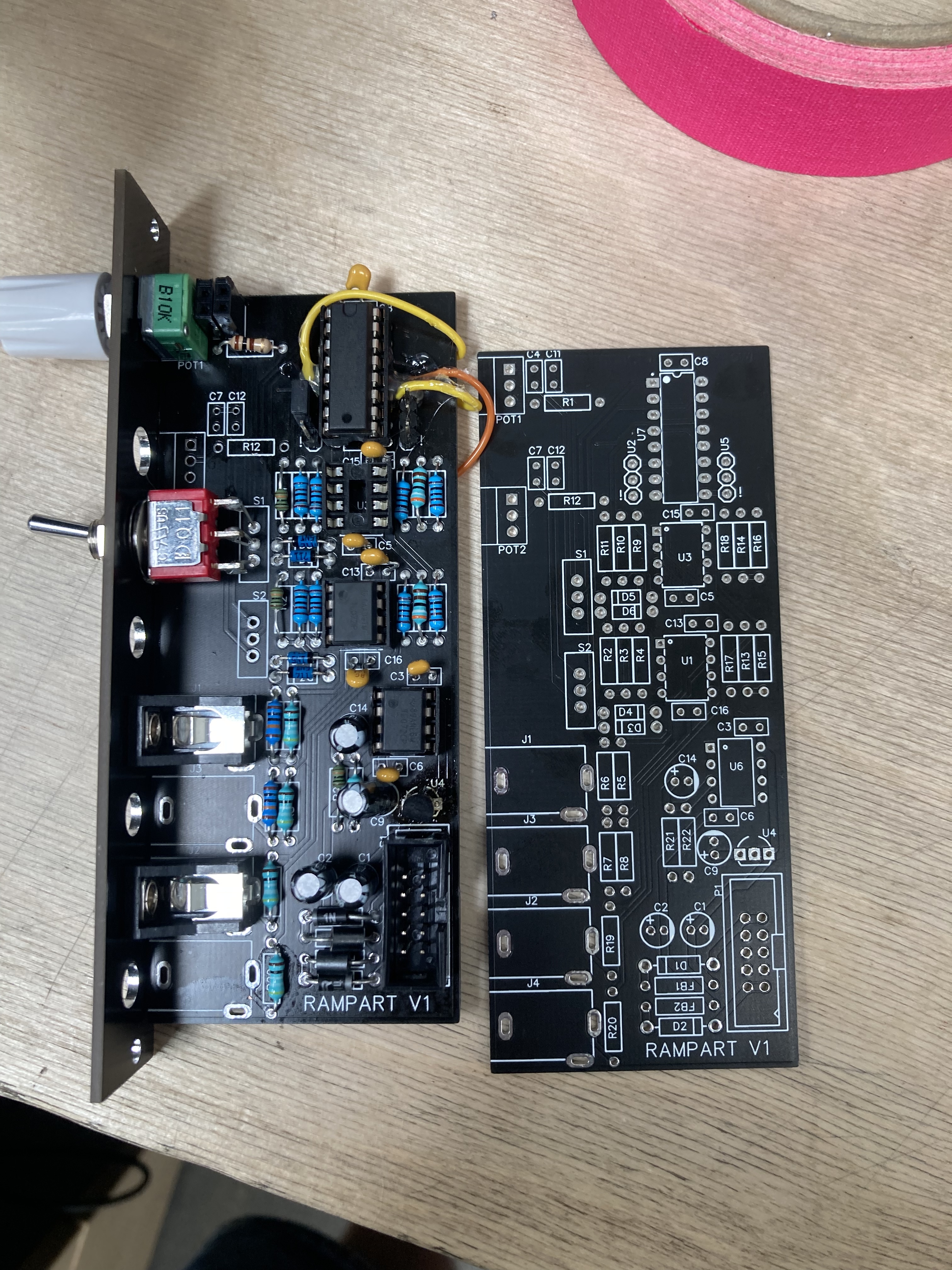
Boards arrived, found a few errors (one day I’ll make a board without stupid mistakes!) but a cut track and a few tacked on wires should hopefully resolve them. Will get it on the scope and tested this weekend, maybe even some video stills if all goes well!
#20 — phosphenes · 2022-06-16
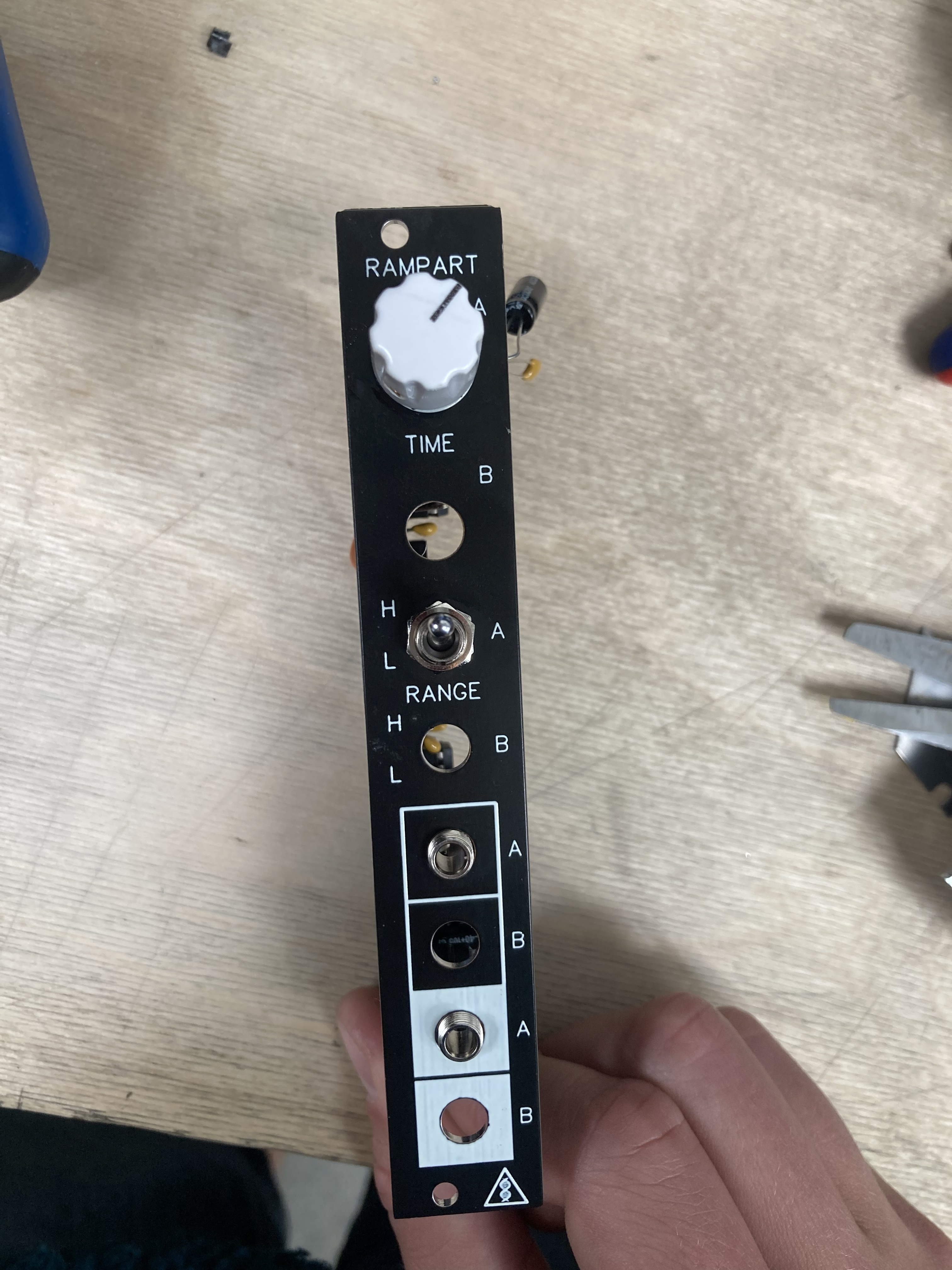
Front panel design was just thrown together quickly, obviously I’ve copied the Castle design style but if anyone has any suggestions or wants to help do a nicer front panel please let me know.
The bottom Jack is pretty low on the panel, it fits in my case fine but is closer to the bottom rail than any other module I own, does anyone see this being an issue (other than aesthetically)? I’m tempted in the next version to go for the 2 x 2 vertical mounted jacks like on some of the Syntonie modules.
#21 — Marizu · 2022-06-16
This looks cool, but I’m a bit concerned about the positioning of that bottom jack.
Different rail profiles have different thicknesses and leave slightly different amounts of space between the rails. I’m sure that I saw the specification of this somewhere but I can’t find it, now.
I’d just stick to the PCB dimensions that you find on commercial products to be safe.
#22 — phosphenes · 2022-06-16
The PCB is 110mm tall which seems to be the maximum that most manufacturers adhere to. Hopefully its fine but may just need to shift the mounting holes on the front panel up a bit on the next revision.
#23 — creatorlars · 2022-06-17
phosphenes wrote:
The PCB is 110mm tall which seems to be the maximum that most manufacturers adhere to.
Just for reference, LZX frontpanels are 128.5mm tall. Rear PCB assemblies are always centered to that height and are 4370 mils tall (~111mm tall) and ((200 * HP) - 20) mils wide (so that would be 780 mils or ~19.81 mm for 4HP.)
#24 — mrfang · 2022-06-30
Cool design. But as a minor quibble: monostable is an adjective and not a noun.
#25 — joem · 2022-06-30
In the electronics world, it’s not uncommon to casually use it as a noun, in place of “monostable circuit” or “monostable multivibrator”. I’ve definitely seen it before.
#26 — phosphenes · 2022-06-30
I think you are technically correct, but I’ve definitely heard it used as both a noun and an adjective, I was certainly taught with it used as both. I wonder if there’s a British English / American English difference in general use?
#28 — reverselandfill · 2024-05-23
did anything came out of this project?
it looks very interesting , a cool addition to the Castle range and possibly a starting point for DIY / bigger projects!
it would be nice if you have a updated / corrected schematic, so people could build it themselves
#29 — phosphenes · 2024-05-24
Hey thanks for the bump! Had a busy year so video projects got sidelined.
Coincidentally I actually picked this back up this week, I breadboarded a new version which was working well, I’ll finish the PCB and get it ordered soon!
#30 — phosphenes · 2024-06-07
Prototype PCB went out for order this week and hoping to receive it (and a few other prototype boards) next week.
There’s some ergonomics to review as I’m squeezing 4 jacks, 2 switches and 2 knobs onto 4hp but I’m optimistic it will be okay!
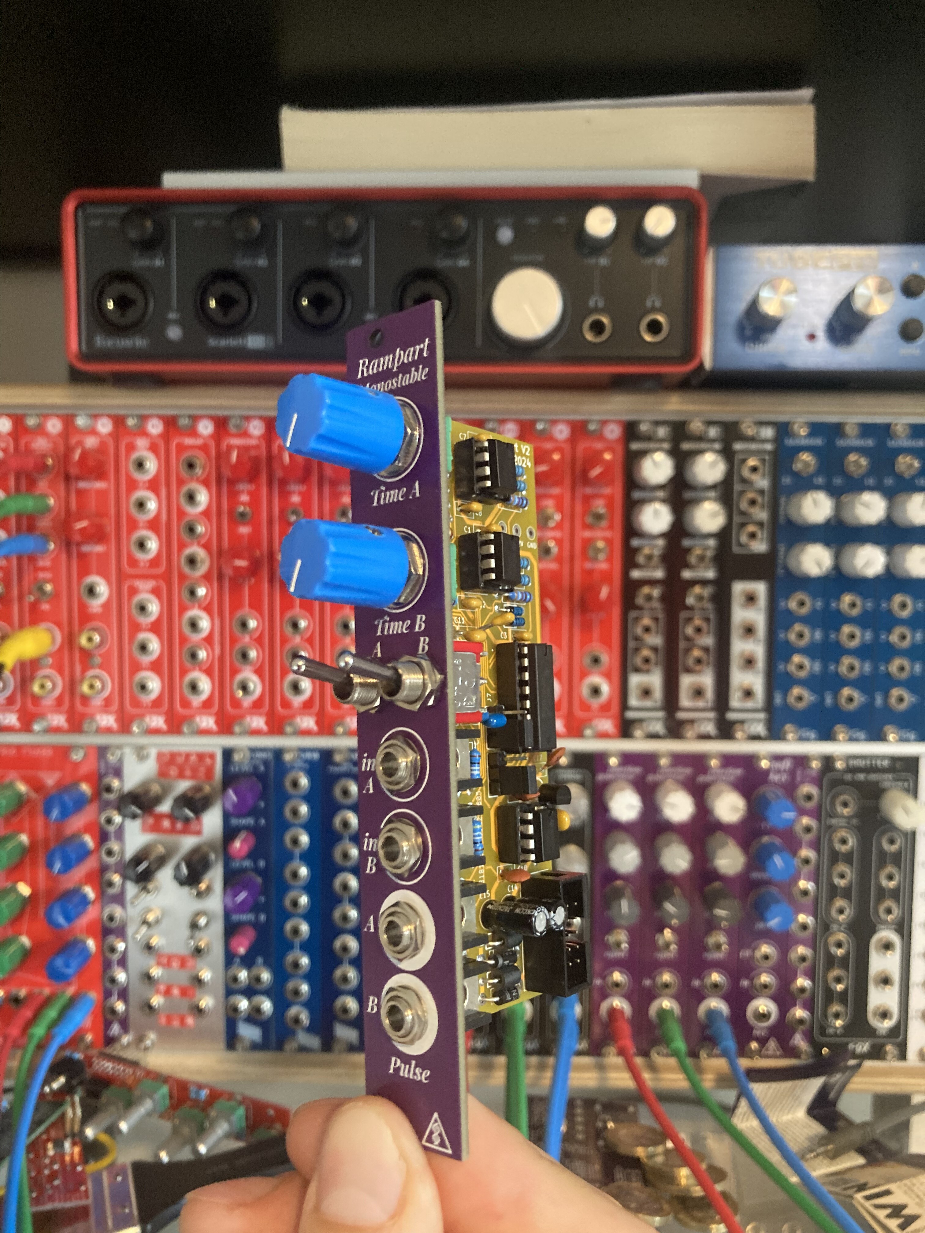
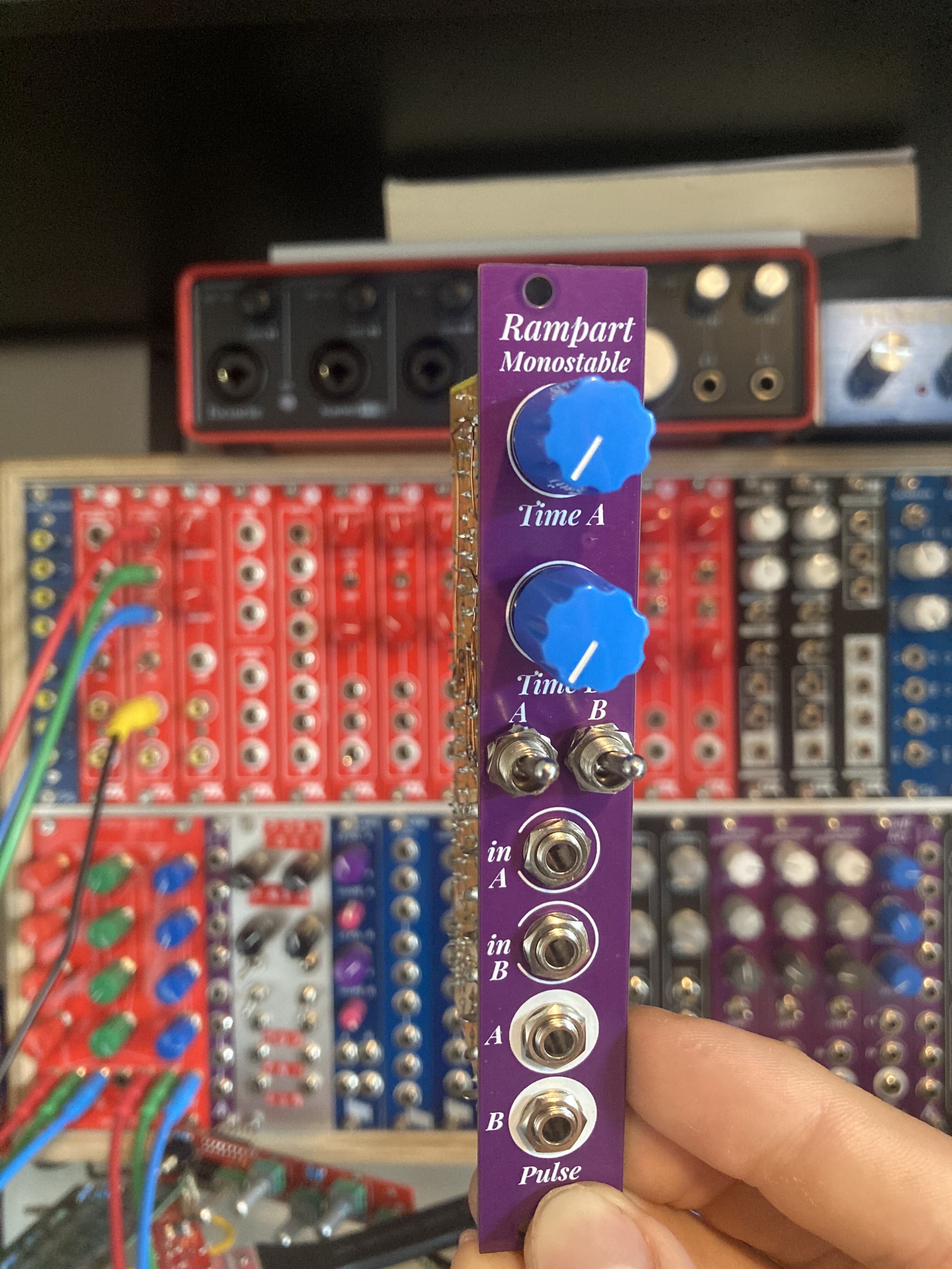
#31 — phosphenes · 2024-07-02
We are GETTING there!
Needs another board revision, but I’m broadly happy with the layout