Topogram - noisy output
Category: Helpdesk · Tags: — · Posts: 28
#1 — dryodryo · 2022-11-07
Hi,
I know it’s a legacy product, but wanted to ask about the noise I’m seeing in Topogram. I got mine used, but it is in absolute mint condition. I’m seeing diagonal lines in the output, especially evident in the darkest portion of the picture.
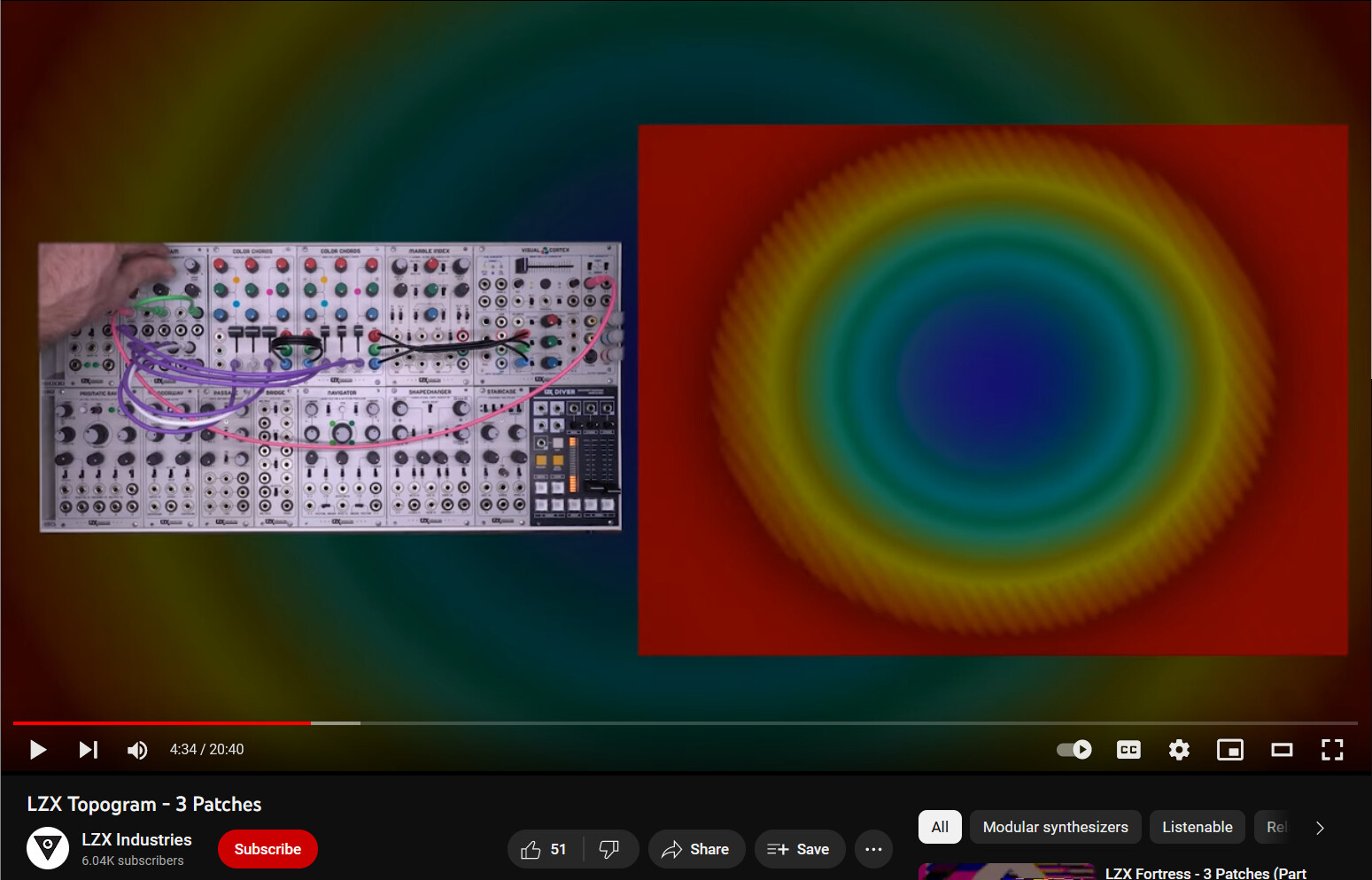
At first I thought maybe it was an issue with the unit, or maybe the power. But then I saw that the noise is present in Johnny Woods’ “3 Patches” video posted three years ago. It’s most evident at around 4:30.
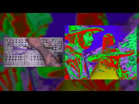
https://www.youtube.com/watch?v=TAWQ-dentJg
So, is this a known issue? Any chance of getting a clean output? I’m totally willing to pay for repair or modification.
Thanks
#2 — dryodryo · 2022-11-07
Another screen capture from official video, showing the icky noise, with just an LFO going into Topogram source input
#3 — Z0NK0UT · 2022-11-07
I am sorry you are finding the lines distracting. Legacy LZX modules are sensitive to power supply noise. Modules with high gain functions amplify power supply noise more than others. This is what inspired the shared module-based power supplies used by Gen3 modules–our latest attempt at making the cleanest signal possible in analog video.
#4 — dryodryo · 2022-11-07
Thanks Chad! Power is coming from Doepfer PSU3. Any ideas on how to reduce the noise?
Would it be possible to construct an adapter, or modify a legacy module, to accept power from DC Distro? Would that make any difference?
#5 — monads · 2022-11-07
I have my Topogram in same Doepfer PSU3 case! I’m wondering if the Trogotronic m05/silencer would help…
#6 — monads · 2022-11-07
^just tried an m05/silencer…no noticeable improvements.
#7 — Z0NK0UT · 2022-11-07
I think it is just the nature of the beast–and the reason we had to slay said beast with the new modules. Johnny is using the best/quietest power supply option in the video, designed by LZX and employed in our old Vessel case.
#8 — joem · 2022-11-08
Not surprising the m05/silencer didn’t work. It’s almost certainly designed to get rid of noise in the audio range, not the video range.
#9 — monads · 2022-11-08
That makes sense!!! Least now we can rule out that option.
#10 — dryodryo · 2022-11-08
Z0NK0UT wrote:
I think it is just the nature of the beast–and the reason we had to slay said beast with the new modules. Johnny is using the best/quietest power supply option in the video, designed by LZX and employed in our old Vessel case.
Hmm. OK. Well, since Topogram is so incredibly awesome, I anticipate that there will be some iteration of it in the Gen3 lineup. Down the road, of course.
#11 — dryodryo · 2022-11-22
I’m finding that the level of visual noise in my Topogram is severely limiting my creative options. I can only use certain color combinations and modulation speeds to mask the noise. Pretty disappointing, especially considering how expensive the module was. Frankly, I’m surprised that this made it out the factory door in its present state. Either no one noticed the design flaw, or it was knowingly released with the design flaw. All the more reason there should be an updated Gen3 version, or module with similar functionality.
Thanks.
#12 — Z0NK0UT · 2022-11-23
Topogram takes a signal and sends it to a bunch of soft keyers, the outputs of which are all tuned to not overlap with one other. This can be accomplished with new LZX modules by multing your signal (using Sum/Dist) to as many FKG3’s as you need, dialing in the desired threshold and softness of each keyer, and controlling the thresholds simultaneously (using Matte).
The edge distortion visible in the Topogram 3 Patches video only happens when the gain is at its highest. This is a bit of overdrive that Topogram allows and it can be useful, if that’s what you’re after. The edge distortion goes away when you turn down the gain (or attenuate external control voltage). This is the nature of an Expedition-series high-gain sequential soft keyer. It is the character of the module–much like the character of an analog audio filter module, which might distort or break up at certain settings.
#13 — dryodryo · 2022-11-23
Thank you Chad. Before this particular Topogram became available on the used market, I was contemplating the multi-FKG3 workflow. Unfortunately, that is beyond my budget at this point.
Please note that, at least with my Topogram, the noise issue occurs even when the Gain is at 12 o’clock. Not just at high Gain settings. This is what I was talking about, how this issue limits my creative options. If I want anything close to a hard edge, I have to choose my color palette very carefully to mask the noise. And modulation needs to be very fast; once again, to mask the noise. Slow or no modulation makes the noise stand out like a sore thumb.
Maybe once I have the financial wherewithal, I might think about doing something with Keychain x3. That should be good for a four-level sequential hard edge key. Video multed into Keychain inputs, all three thresholds set by a single Matte channel.
But in a best case scenario there would be an updated Topogram, or similar sequential keyer, in the Gen3 lineup. It really is one of the coolest modules I’ve seen, and it’s so sad that it has a near-fatal flaw.
#14 — creatorlars · 2022-11-24
dryodryo wrote:
It really is one of the coolest modules I’ve seen, and it’s so sad that it has a near-fatal flaw.
This is how most of the Expedition era felt like for me, with EuroRack power in general, any time we tried to do higher gain circuits. Does your Topogram have the copper shield installed between the two boards in the rear? There should be one in there – if not, no wonder you’re seeing some noise.
#15 — monads · 2022-11-24
Mine does have the copper shield installed!! Never knew what that was for until now!
#16 — dryodryo · 2022-11-24
creatorlars wrote:
Does your Topogram have the copper shield installed between the two boards in the rear?
@creatorlars, I do see a copper shield around the vicinity of the power ribbon header. It’s not shielding the entire middle board, which I presume is the logic part of the sandwich.
Would it make any sense to try to enhance that shielding? E.g. wrap the whole middle board in some kind of insulated metal foil? I guess some EM radiation is always gonna leak through the spot where the power ribbon header contacts the rear and center boards.
Thanks!
#17 — creatorlars · 2022-11-25
dryodryo wrote:
Would it make any sense to try to enhance that shielding? E.g. wrap the whole middle board in some kind of insulated metal foil? I guess some EM radiation is always gonna leak through the spot where the power ribbon header contacts the rear and center boards.
Moving the entire power entry/supply to a separate PCB has been the best approach (as done in the Gen3 power packs.) I would not try to further modify the existing copper shield.
#18 — dryodryo · 2022-11-25
Thanks, so I guess you’re saying that the power circuit isn’t on a separate board for pre-Gen3 modules, and issues such as this were one of the motivations for the current design. Isolating the power circuit to a separate daughter board cuts down on noise as well as streamlines the manufacturing process.
#19 — creatorlars · 2022-11-26
Yes, those aren’t all of the factors involved, but that’s all correct! We designed the Gen3 architecture with an “aquarium” ecosystem in mind: create an ideal 12HP or 8HP tank to hold the fish (aka the video circuit.) The power supply backpack is like having all the water filtering happening in an external unit, so that only the cleanest water ever enters the aquarium. If you have power entry/filtering on the board with the circuit, you are potentially dealing with dirty power and analog circuits in the same place – now crosstalk and noise can pollute things. Standard EuroRack power circuitry (basic filtering, no internal power supply) is like a pet shop where the water supply is shared across all the tanks – a dead fish in one tank may pollute the rest.
These are terrible metaphors.

#20 — Boneoh · 2022-11-26
LOL Those are great metaphors!
I can understand it without thinking

#21 — Vdot · 2022-11-28
I’ve been meaning to ask for a while. If were to feed modulation CV from my dirty-powered audio rack to a completely clean, barrel-powered GEN 3 system. Would I automatically lose all the noise-reducing benefits of GEN3’s clean power?
Would it be the equivalent of sticking one end of a hose in my dirty aquarium, sucking on the other end and then dropping it in my clean aquarium?
#22 — creatorlars · 2022-11-28
Vdot wrote:
Would I automatically lose all the noise-reducing benefits of GEN3’s clean power?
Not quite. In the analogy, “water” is the power supply, not the signal path. So if you generate a noisy signal, then process it with Gen3 modules – the noise is still part of the signal. The Gen3 modules can’t filter out the noise because that would interfere with the bandwidth of the system (low noise and high bandwidth is a tall order!)
Maybe a better analogy in this case is the traditional process of recording music in a studio.
One studio might have a very high end, ultra low noise mixing console with extremely high fidelity EQ or DSP functions.
But the band might still come in and record a track using a crappy fuzz pedal with an audible hum, or mic a chainsaw with a $2 contact mic, or whatever. Even though the signal source has some noise in it doesn’t mean that the noise will be inherited by everything going into the mix – it’s isolated to the input. For example, if you turn down the fader for that channel, the noise disappears.
A wise mixing engineer will of course adjust the EQ/filtering or even apply a noise gate to the noisy channel so that it sits with the frequency spectrum of the mix as a whole. Maybe more “mastering tools” would be nice to have in the video synth environment (notch filter, de-noise DSP, etc).
And of course some bands may just record at home on an old four track and not care too much about noise in the recording – it becomes a creative choice.
#23 — Vdot · 2022-11-28
Ah that’s great to hear. I was worried that simply patching an LFO from my uZeus-powered modules would somehow propagate a general noise to any GEN3 module in the chain.
#24 — dryodryo · 2022-11-28
The issue I’m seeing with Topogram appears to be in the high frequency range. That is, the noise is a semi-regular waveform in the same general frequency as the video signal. Looks like some harmonics of 60 cycle hum.
I haven’t yet had a chance to test the Topogram as a low-frequency amplitude classifier. My assumption is that if I use Topogram to process low frequency signals, the high frequency noise will be present at the output, but its effect will be negligible. And even if it’s an issue, all I’d need to do is send that dirty low frequency output through an audio module of any kind. That would filter out all of the high frequency crap.
Is that reasonable? And wouldn’t that scenario apply to any low frequency signals, regardless of their point of origin or the specific character of the high-frequency noise? So really, it’s not an issue with audio modules, they’re generally not fast enough to resolve anything above ~20 kHz, including video rate power hum.
#25 — creatorlars · 2022-11-29
dryodryo wrote:
The issue I’m seeing with Topogram appears to be in the high frequency range. That is, the noise is a semi-regular waveform in the same general frequency as the video signal.
You’re describing the noise created by a switching power supply, which often oscillates around 100KHz to 1MHz. So it’s usually filtered out of an audio path, but that’s right where we don’t want it, for video!
In Topogram, we used a switching power supply into low noise LDOs (a similar architecture to Gen3) but due to nesting it inside the assembly had to add a grounded shield to reduce the inductor’s effect on the rest of the circuit. So you are more than likely seeing the reduced ripple from that circuit. EIther that, or you are seeing the EuroRack noise floor, or both in concert. The noise is overall much higher than other modules because there’s a large amount of gain in the circuit. With that design, we realized if we wanted to do more high gain circuits and expect clean response, starting with a much lower noise floor in the first place was necessary.
#26 — creatorlars · 2022-11-29
dryodryo wrote:
Is that reasonable?
Yes, your understanding is good! Think of it like in audio mixing; if you’re doing a traditional dance track you will usually shelve the mix around 150Hz so that the subharmonic of the kick drum gets a nice clean tone, and then layer that with a transient that has its low end scooped out.
So really, it’s not an issue with audio modules, they’re generally not fast enough to resolve anything above ~20 kHz, including video rate power hum.
I’m sure some audiophiles would argue about that with us (the supersonic components of the signal path and how they may interfere with clarity in the mix) but, yes! If you are sampling CD quality audio, a 500KHz switcher ripple is well above the nyquist frequency.
#27 — creatorlars · 2022-11-29
So if you are the circuit designer and want to get rid of the switching ripple entirely, but need to account for modern low voltage switching power use everywhere, what do you do?
You create local switching power supplies with a controlled ripple frequency, and immediately post-process them with LDO regulators with a high PSRR characteristic designed to target the frequencies you are generating. It’s a bit of controlled chaos designed to both introduce and nullify the high frequency ripple in one step.
Many of the early generation of switching power designs for EuroRack were using standard LDOs that were more suited to traditional linear power supply architectures, which explains why they wreaked havoc on video modules (no filtering of those high frequencies at all!). When Visionary series was developed and up through Visual Cortex’s release, EuroRack was mostly linear power supplies, with Mono Rocket, Analogue Solutions, Doepfer being the only case/power manufacturers around.
#28 — dryodryo · 2022-11-30
Thanks as always for the education, @creatorlars !
I also realized after posting that in the worst case scenario, high frequency noise can be filtered from any low frequency modulation by merely sending the signal through a sample and hold circuit locked to vertical sync. I do that routinely on near-frame-rate modulation to avoid horizontal tearing and banding. The modulation value is held for the entire field/frame. In this scenario, there will never be a pattern onscreen from the high frequency noise. The worst you’d see is a little bit of flicker among fields/frames, and the high frequency noise would need to be very high to even see that.