Sync busboard design - for Cadet DIY systems
Category: Unknown · Tags: cadet · Posts: 76
#1 — reverselandfill · 2018-10-15
so… I am designing a busboard for the sync bus connections on a Cadet system.
this is what I have. I’m creating a part now (in Eagle, so that takes a while) for a 7 position screw terminal.
to connect several sync busboards together (on both sides)
I’ve made 14pin shrouded headers with big oblong pads for easy soldering.

What other features shall I include?
I was thinking: some alternative pins for custom sync cables / pcb connections.
and text indications of what signal is connected to what pinrow. + polarity
the pcb is 16.5 x 4.2 x 1.2 cm. is this size ok, or should it be bigger / smaller?
#2 — CountFunkula · 2018-10-15
+1 for “aux” pins for non 14-pin sync connections. Pads for RCA jacks or even just screw terminals would be super handy.
#3 — reverselandfill · 2018-10-15
update 1
screwterminals , names & extra gnd pads added.
mmh. yeah, RCA is the method the other modules use right? but that is coded signal I think. so not directly connected to the pins I have here. I will ask the experts @creatorlars ? would this be useful ? or does nobody need this added?. I could make separate traces.

maybe I can add a few rows of screw terminals in between the rows of headers. then you can choose what type of connection you solder in place.
to do:
I have to measure the screw terminal to see if it fits on the board.
#4 — CountFunkula · 2018-10-15
reverselandfill wrote:
mmh. yeah, RCA is the method the other modules use right? but that is coded signal I think. so not directly connected to the pins I have here. I will ask the experts > @creatorlars> ? would this be useful ? or does nobody need this added?
True. I think the 14-pin sync is 5v TTL and the RCA sync is composite sync. There still might be some fun to be had taking the TTL sync out via RCA (or BNC!) for sync “experiments”

#5 — luix · 2018-10-16
the RCA sync signal is specially interesting for large cases with Expeditionary, Visionary or Orion series so having a RCA or even minijacks (both right angled) its interesting
Regarding the board design I would try to use thin traces to reduces resistance… maybe its irrelevant but with this small signals (1v) every mV counts, also I remember that its not recommended to use long cables… for the same reasons.
I would suggest to even add buffers. Im thinking this for large multicase setups… of course this means your bus board will stop veen passivr and will need power from the power bus… maybe Im complicating stuff
#6 — reverselandfill · 2018-10-16
thanks for your thoughts!
I’m not sure what to do with the RCA / jack connectors now.

The thing is that I don’t have any way to test this method because I don’t have these type of modules.
I only have DIY stuff.
How do people connect the sync of Cadet modules to their VC now?on the buffering: this sounds interesting. but maybe I will do a passive board and a buffered board later on.
the trace width is currently 0.032 inch. so 0.12 would be better? Or even smaller?
#7 — CountFunkula · 2018-10-16
reverselandfill wrote:
How do people connect the sync of Cadet modules to their VC now?
VC has both 14-pin sync and RCA in/out
#8 — creatorlars · 2018-10-16
If you want RCA sync output from your Cadet 1, you need to attenuate the CSYNC signal to ~0.6Vpp (2X gain), buffer it with a video op-amp (LM6172) and drive it thru a 75 ohm output resistor and large AC coupling cap to the RCA jack.
#9 — reverselandfill · 2018-10-16
mmh. I have to think this over.
I will make a passive board anyway. but…
A multi purpose busboard would be cool.
#10 — joem · 2018-10-17
luix wrote:
Regarding the board design I would try to use thin traces to reduces resistance… maybe its irrelevant but with this small signals (1v) every mV counts, also I remember that its not recommended to use long cables… for the same reasons.
I don’t think that’s right… resistance = resistivity × length / area, so the thicker the conductor, the more cross-sectional area there is, and therefore the smaller the resistance. That also explains why the longer the cable the more resistance.
#11 — luix · 2018-10-17
oh by no means take what I said as written in stone, Im still learning my way into electronics so what @joem says is probably right
#12 — reverselandfill · 2018-10-17
ok, so what would be a good trace width?
and a buffer question: if I were to buffer the signals, what would this mean… 1 buffer per signal?
So six buffers on the input.
something like this:

#13 — joem · 2018-10-17
Re:trace widths, the bigger the better! That said, I don’t off hand know what a good practical minimum would be. There are a lot of places with “trace resistance tools” or “trace resistance calculators” so if you really want to get precise, or just play around with some numbers, I’d say check those out. I know for eurorack power busboards it’s a good idea to make the ground thicker than the others, so that might make sense here too, maybe?
Re:buffers, that makes sense to me (though I’m no expert!). But I’d definitely use video rate op amps (LM6172) like Lars mentioned, since the sync signals probably wouldn’t be the cleanest through slower TL072s.
#14 — reverselandfill · 2018-10-17
thanks for the reply. I’m no expert either, so all help is welcome

I think I’ll make make a groundplane then, and fat traces for the other signals.
I’ll check those sites too.
For the opamps. yeah, I just used the tl072 as a marker. I don’t have a Eagle part for a LM6172, but those pinouts are the same. (I’ve updated the picture though)
from the calculator site
resistance is 0.125 ohm for 0.032 inch trace
0.0801 for 0.5 inch trace
#15 — creatorlars · 2018-10-17
Use an all over ground plane and nice thick traces for your power rails (40mil) – or 4 layer board with internal planes for power and ground. TTL sync signal traces can be thinner (12mil) since they are not carrying current. Space them out a bit if you can to minimize crosstalk.
For buffering syncs, no need to do that for the H/V pulses sent out on the CV/Gate bus, they are already buffered. For the 14-pin TTL signals, you buffer them with 74HC14 as shown in the Cadet 1 datasheet (they are also already buffered.)
If you want to convert TTL CSYNC to an RCA video signal (black video with sync only) you need an extra buffer and driver (you need to attenuate the signal from 5V to 0.6V at the input to the buffer using a resistor divider and then drive it thru a 75 ohm resistor and AC coupling cap (47uF or so should be good.)
#16 — reverselandfill · 2018-10-17
Hi Lars! Thank you for the clear response !
So you are saying that buffering the TTL sync signal is not really necessary?
Does this also take into account that if someone has multiple cases and want to connect +10 VCO’s?
#17 — creatorlars · 2018-10-17
I haven’t reached a point at which chaining the syncs from a single 74HC14 buffer is insufficient (even with 10+ modules attached to the 14-pin bus), but you could buffer on the busboard if you wanted to. (One sync input header, multiple sync output headers.) It certainly wouldn’t hurt anything. You’d need 5V power supply though, to do that (so 78L05 or similar.)
I may be short on time to draw up some circuits for you but if you can post screenshots here I can reply and offer advice.
It’s great you’re doing this!! I really want to document all our standards and some best practice circuit examples in a formal document and open document at some point, and this is a step in that direction. It’s so exciting to me to see the community taking the initiative on projects such as this.
#18 — reverselandfill · 2018-10-17
cool. This community forum is the best. I learn so much from everybody


I’ll keep posting my progress .
#19 — reverselandfill · 2018-10-17
ok. test circuit for buffers, 5v and cv/gate bus connection. I’m unsure about that last one.
Can these nets be connected in this way?
The purpose would be to connect Castle & Cadet modules to the same busboard. maybe I have to put two jumpers in place. (?)
and the 7805, should I use a LM7805 , or a small 78l05?
I guess the 74HC14 won’t use much power, so maybe a 78l05.

#20 — creatorlars · 2018-10-17
This looks OK! 78L05 should be fine to just power a single IC. (so use the IC3 instead of IC2 circuit.)
For the HSync/VSync on the power bus, these are driven as LZX standard 1V signals from the sync generator. You could re-buffer them, but it would require additional opamps (so I don’t think you need to worry about it.)
#21 — reverselandfill · 2018-10-17
is it better to put the C1 cap at the 12v input or use it at the 5v junction?
Are the sync signals of the Castle Clock/ VCO also 1v then?
#22 — creatorlars · 2018-10-17
The 10u cap (C1) should be in parallel with C3, on the regulator input.
C2 can be omitted so long as C4 (and the regulator output pin) are directly adjacent to the IC1 power pin.
That’s how I’d do it anyway.
The CV/Gate bus syncs are always 1V (buffered with video opamps) same as the frontpanel sync outputs, so I’m assuming that’s what Castle will lock to. It probably also works fine being sent the TTL 5V signals too.
#23 — wednesdayayay · 2018-10-17
this is so cool
I’m so happy to see this community growing
I will always try to patronize community driven output
although I don’t have an 14-pin sync modules currently (I’m using all RCA)
#24 — reverselandfill · 2018-10-17
I’m on a roll. @creatorlars: by “space them out” (the sync traces) , you mean something like this?
So they don’t run parallel to each other?

#25 — creatorlars · 2018-10-17
You shouldn’t need to spread them out like that – I just meant to not group them tighter than necessary. 8-12mil traces, spaced the same as the 2.54mm pin headers pads will be fine! A little crosstalk here is normal and OK, it gets cleaned up by the 74HC14 buffer on the receiving end.
#26 — reverselandfill · 2018-10-17
okay!
now I’m thinking about connecting several busboards. there should be a screw terminal on both ends.
The screw terminal blocks that I have here are bigger than the 14pin header pitch, I think you can find ones that are the same as the headers. In that way, you can leave out the buffers on the 2nd pcb and solder a 7pin screw terminal in place of the 1st sync output header. . or maybe I’ll make a separate placement. not sure yet
I think those 14pin IDC connectors have 2.54mm pitch. I’ll check.
#27 — creatorlars · 2018-10-17
My suggestion would be to keep the buffer on the busboard anyway… might as well, it’s cheap, and that way you are rebuffering and distributing on each sync busboard. For very large systems this may be a good idea.
#28 — reverselandfill · 2018-10-17
good point.
I’ve added a input header . and a 5v indicator LED. the placement of the power connector is maybe not great

next is finding a way to connect the busboards across cases.
I’m thinking of a panel with 14pin IDC headers (SMD the bottom, TH on top. to prevent pins sticking through the front of the panel)
and then use a flatcable between cases.
or maybe a 7pin plug, like a din cable or so. or a large multipin XLR ? maybe only 6 pins. GND is already there(?)
#29 — peloazul · 2018-10-17
If you are making the busboard active (buffering, right?) - then why not just add the 14pin sync -> composite/RCA sync circuit? That would make it fit into current systems pretty easily.
Just thinking out loud, IANAEE.
#30 — reverselandfill · 2018-10-17
IDK.
I am hesitant because I can’t test this (as I have none of such modules)
and I wanted to make a simple busboard.
but you know. feature creepings.
I’m still not really sure why people would need this, as the RCA modules already use a handy system
But there is something to say for adding it all on 1 board.
If I were to do this, what would be a good amount of RCA connectors?
It might get a bit crowded if I add 8 or more of those.
other musings… if one would use the Cadet sync generator and add a LZX module that needs sync…
It might be handy to have this connection.
#31 — peloazul · 2018-10-17
I’d guess that one connector for in, and one out would be sufficient were it considered as a case to case connector?
I would also guess you might need a way to select whether sync in came via 14pin IDC connector or RCA jack? (I’d guess not both at the same time would ever be wanted.)
#32 — reverselandfill · 2018-10-17
mmh… another good point
Question: Do all LZX sync generator modules have a 14pin output?as for connecting cases…
I guess most other signals beside the H-sync and V-sync are not needed much?
or can the other signals be extracted again?
I’m trying to make this as DIY friendly as possible. taking into account all possible future DIY modules.
#33 — peloazul · 2018-10-17
iirc - the sync generators are Cadet I, Visual Cortex, and Memory Palace. C1 and VC both have 14pin sync output… but I don’t know whether MP does.
#34 — reverselandfill · 2018-10-17
update.
power header is better like this.
sync in header is moved to the edge of the board.
musings: I’ve routed the sync in signals paths around the power header. Does it matter … or can I just route them between the power pins . I was thinking of interference…

to do:
measure the screw terminals again.
add funky graphix. I have some ideas already

done# the pcb holes are now symmetrical
#35 — reverselandfill · 2018-10-17
question: how does the 74HC14 buffering work? I would not have thought to use these IC’s this way. they look “backward”?
#36 — wednesdayayay · 2018-10-18
ethernet or HDMI offer a lot of connections and easily available cables as well but it sounds like you’ve got things sorted
#37 — reverselandfill · 2018-10-18
that might be a good direction.
And I guess the cables can be a bit thinner, as the signal gets rebuffered on each busboard.
something with a good steady plug with some locking mechanism and a round cable would be optimal in my opinion.
#38 — VanTa · 2018-10-18
RCA in this board will be useful in the case of a system without VC, like mine.
It will be useful to drive Cadets IV or IX from a MP or sync a Prismatic Ray or other Expedition form a Cadet I Sync Generator.
Although, this can also be built into a little module, ‘sync distributor’ or smt. and be independent from the sync busboard itself.
Very interested thread indeed.
#39 — reverselandfill · 2018-10-18
based on this:
If you want RCA sync output from your Cadet 1, you need to attenuate the CSYNC signal to ~0.6Vpp (2X gain), buffer it with a video op-amp (LM6172) and drive it thru a 75 ohm output resistor and large AC coupling cap to the RCA jack.
something like this?
output voltage is now 1.207. (2x 0.6) or should it be 0.6 in total?

If I were to add this, we need to do a prototype test. beta testers would need to check several scenarios.
(maybe this is overkill and I’m being overtly careful. want to do it right. and not destroy expensive modules

#40 — creatorlars · 2018-10-18
@reverselandfill The circuit is looking correct, however LM6172 needs 499R input resistor (insert in node between R3/R2 and U1 pin 3) and needs to see some resistance in the feedback loop (add 499R or 1K resistor between U1 pins 2 and 1.)
For driver amplitude you want 0.6V total (standard video sync amplitude is 0.3V, so we want to drive at double that amplitude – when it is terminated by 75 ohm on the other end, the 0.3V amplitude is restored.) Essentially you’re creating a valid video signal here, where video is just black, but can be received by a display or any video device with a sync/genlock input.
Regarding RCA sync to 14-pin sync, there is not really a better or cheaper or easier way to do this than the Cadet I circuit, so unless you want to integrate Cadet 1’s PLL and MCU components into the busboard design, I wouldn’t recommend it. The other way around (14-pin sync to RCA sync) is easy with the opamp buffer as shown.
The original Video Sync Generator, Cadet I Sync Generator (which is a simplified version of it) and Visual Cortex all provide 14-pin sync output.
Memory Palace and Vidiot (two other master sync generators for an LZX system) provide only the RCA sync output. However in these use cases, they are not really “master sync” modules, since they do not provide frontpanel sync outputs – systems using these as their master sync source can be though of more as “Memory Palace + expander modules” rather than Visual Cortex or Cadet 1, which form the basis for a holistic system (as we’ve imagined it, anyway.)
As far as connecting sync between cases, I would recommend including a slaved sync generator (Cadet 1) in the second case as opposed to trying to connect the 14-pin connections through some sort of DIN cable or similar. This way the cable can be as long as it needs to be, uses simple parts, and you don’t risk any weird connector or cable length related crosstalk issues.
We moved to RCA sync I/O on all production modules starting with Visual Cortex, because this is already an established standard (Genlock in/out on broadcast devices!)
We’ve stayed with the 14-pin connector on DIY modules because… well, the goal of these modules is to teach people how video circuits work, and having access to them all as TTL signals on a ribbon makes it easier to tinker and expand!
Visual Cortex provides the 14-pin sync outs to support Cadet and legacy formats, so we recommend including this module in your system if you want both worlds. I do see some merit of the RCA sync output on the busboard, so that people with DIY systems can add production modules to their rigs without requiring anything else.
#41 — reverselandfill · 2018-10-19
update.
I changed the resistor values to get 0.608V. but with the 499r between I’m unsure what voltage I will get there. I’m not really a math wiz. I guess I can breadboard it.
Do I need to add 1n4001 diodes & ferrite beads at the power connector?

As for the connecting cable:
You mean that one could install a 2nd C1 in the other case and use the sync thru/output from C1 in case 1 to drive the sync input on the 2nd C1? (using a RCA / BNC cable)
That sounds solid.
note: I am deciding between right angled RCA or vertical. I have a lumberg vertical RCA footprint in Eagle. The Mouser part 490-RCJ-044 would also be good. But I don’t have the part in Eagle. Does anyone have this?
I can make it myself, but that will take way more time.
#42 — reverselandfill · 2018-10-19
another thing:
I am thinking about ditching the 7pin screw terminal blocks and instead adding 3 jack sockets, so that you can connect busboards together using 3 jack cables.
So the 6 sync signals are packed into the tip and gnd connections of the jack socket.
IDK if this is good practice. but having 7 single wires (per busboard connection) might not be practicable either.
The GND connection is then provided by the power connection.
#43 — LauLindqvist · 2018-10-21
I recently bought a 8 pin M12 cable for interconnecting my two cases containing cadet+castle (soon also the sandins) modules.
For now i use an XLR cable cut in half for power, but wanted to get a cable that is not mixed up with other signal types (to avoid accidentally inputing +/-12 volts to some delicate equipment by mistake), and wanted to include the bus sync signals for my other case.
Initially i thought about hacking it in a much simpler way than what i can read in this thread.
I wanted to interconnect the bus sync by just plugging a 16 pin cable into one of the sockets in the busboard, and then use only the sync signals leads from the ribbon cable to feed the sync signals through the M12 interconnect cable (together with power: ground, syncs, and +12V, -12V), throught the interconnect cable, and then on to the next busboard by plugging the sync signals directly to the busboard through one of the 16 pin sockets,(again via a ribbon cable, but only using the sync pins) power goes through screwterminals on both busboards.
I dont se if this should not work, but havent tested it yet…
Will have to read through this thread a few times before i venture into cutting the cable in half and attaches it between my cases.
@creatorlars Would this (going directly between the sync pins on different busboards) be a viable way to get bus sync between cases?
The cable i bought might be of interest to you also. the connector type comes with all different pin numbers, i went for 8 pins.
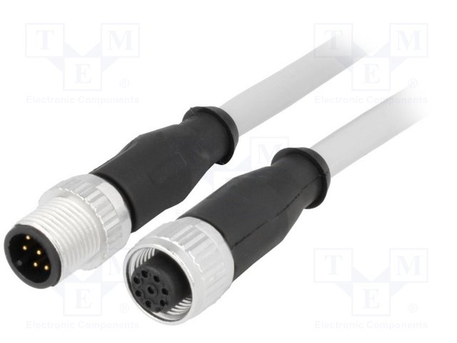
https://www.tme.eu/en/details/21348485882015/connectors-with-cable/harting/HARTING 21348485882015 | Cable: for sensors/automation; PIN:8; M12-M12; 1.5m; plug; plug - This product is available in Transfer Multisort Elektronik. Check out our wide range of products.
Link: 21348485882015 HARTING - Cable: for sensors/automation | TME - Electronic...
#44 — reverselandfill · 2018-10-29
update:
the layout is done. I hope to get some comments on the schematics. is this correct?
if so… time to send it to China!
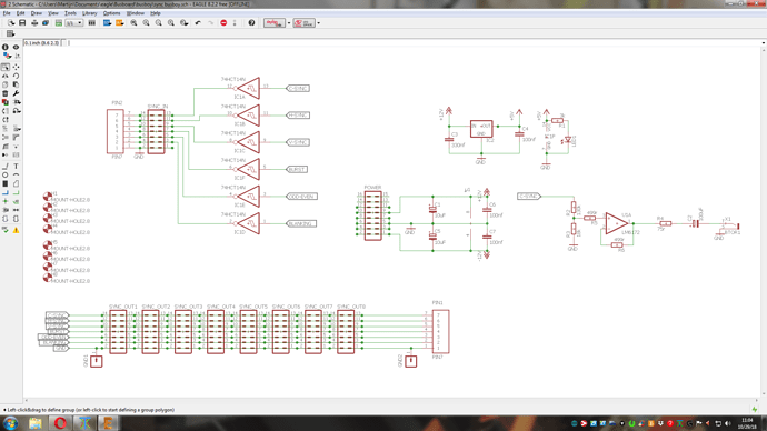

#45 — creatorlars · 2018-10-29
Your HC14 inverters are the wrong way around!
#46 — reverselandfill · 2018-10-29
ha, yeah I thought so.
I was working from the C1 schematic… but there they are positioned this way, because they go to a sync output header

and I got confused
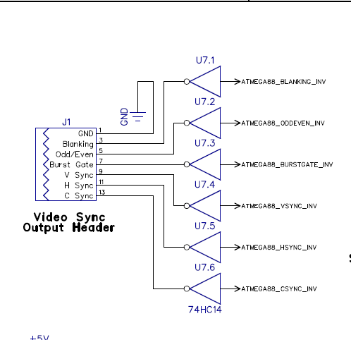
edit:
fixed:


#47 — LauLindqvist · 2018-11-06
LauLindqvist wrote:
Would this (going directly between the sync pins on different busboards) be a viable way to get bus sync between cases?
Browsing the LZX site product pages to drool over stuff i cannot afford at the moment, i found the
https://www.lzxindustries.net/web/image/product.product/2298/image?unique=200f6aa
Video Sync Bridge Cable
So i figure this answers my question: i can indeed distribute the bus sync from one case to another directly connecting the pins on the busboard. Now i just need to figure out which pins to connect for this to work.
#48 — reverselandfill · 2018-11-06
I’ve found right-angled RCA footprints for Eagle.
So what would be the preference?
vertical or sideways?
#49 — creatorlars · 2018-11-06
It’s looking good in the last schematic! There are no reverse protection diodes for the power input though (you can use 1n4001 following the cadet circuits.) This isn’t necessarily required, but always good practice.
#50 — reverselandfill · 2018-11-06
I was wondering if it was nescessary in this case. I’ve added them now.
note: the diodes in the schematic may look weird. but all is ok. there is some very small text that looks like a pin.


#51 — reverselandfill · 2018-11-07
I’m keeping the vertical RCA socket. makes sense to me and they are cheap.
The hole size for the terminal blocks is now adjusted to a larger value. (it was way too small)
I realized that there is an unused op-amp stage. what useful thing can I add??

#52 — reverselandfill · 2018-11-20
ok, the pcb’s are ordered.
#53 — reverselandfill · 2018-12-07
They just came in today! whooo
I’ll test them this weekend. after that, I need someone to test the RCA sync out.
Please PM me if you want to beta test it.
#54 — reverselandfill · 2018-12-10
the first one is ready for testing!

#55 — reverselandfill · 2018-12-10
testing now:
No correct sync yet.

signals are coming through, but…
@creatorlars : shouldn’t there be 2 buffer stages to buffer the sync signals?
I think the sync signals are now inverted. (with only 1 inverter stage) so the sync signal is not working.
- I checked this with a scope
when I bypass the 74HC14, it works.
#56 — creatorlars · 2019-01-05
Yes there should be two stages. I apologize for neglecting to notice that and point it out. The reason Cortex and Cadet 1 only have a single inverting stages is because I am sending inverting syncs to the buffer, precisely for the reason of removing the need for a second 74HC14. Since syncs are buffered at their source, for your busboard I would suggest that buffering them again isn’t essential. But in a very large system it’s probably a good idea. I haven’t ran into a case yet where the single 74HC14 buffer wasn’t enough to drive any number of modules you want.
Another idea for this busboard would simply be to integrate Cadet 1 into it. So the input is RCA sync and you have some wire header outputs to a passive panel for connecting the 1V sync outputs if desired.
#57 — reverselandfill · 2019-01-05
ok, with that confirmed, I’ll make an updated layout.

time for prototype number 2!the builder can decide to solder the buffer & RCA output or skip those sections.
I’ll keep you posted!
#58 — reverselandfill · 2019-01-05
blip

routing in progress
#59 — reverselandfill · 2019-01-08

routing was a bit more complex this time. can anyone check if I did ok?
especially the power lines . and the sync signals
I still think I should do something with the 2nd half of the LM6172. Any suggestions?
maybe a 2nd C-SYNC buffer, but without the RCA connector? (because that wouldn’t fit)
#60 — CountFunkula · 2019-01-10
reverselandfill wrote:
a 2nd C-SYNC buffer, but without the RCA connector? (because that wouldn’t fit)
Maybe just run it to some unpopulated pads as a “DIY/you figure out what to do with it/AUX” C-Sync out? Given that option, I personally would use it to add a BNC connector on a flying lead.
#61 — reverselandfill · 2019-01-10
yeah , that is a good idea.
I’ll make a jumper for it, so that if you do not use this option, the stage is grounded.
(like in the schematic above )
Maybe I’ll add a “experimentation area”.
Question: Shall I leave out the resistors + capacitor, like in stage 1?
Maybe I can fit them, but if it is an experimental area, It might be useful not to have a predetermined use.
#62 — reverselandfill · 2019-01-14
new stuff. 2nd c-sync bus for alternative connectors. / extra output.
When not used, there is an easy grounding option next to the LM6172. so a bypass = 2 jumpers
It all fits, so that is cool! The pcb has a less funky shape, oh well
And I’ve added one extra sync header. so there are nine in total!
Last check before I send it to China!


#63 — wednesdayayay · 2019-01-14
I don’t know anything that would be helpful here but thank you for doing this!
#64 — reverselandfill · 2019-01-16
Ok, it is in production now.
#65 — reverselandfill · 2019-01-25
Ok, they just came in! All is soldered now (I’m a few headers short), next is testing.


#66 — peloazul · 2019-01-25
Cool! Excited to see!
#67 — reverselandfill · 2019-01-25
First test is good!

I need somebody to test the RCA sync output. Volunteers?
#68 — wednesdayayay · 2019-01-25
I have a visual cortex and other LZX RCA sync modules/vidiot, I’d be happy to test it out.
#69 — reverselandfill · 2019-01-25
Where do you live? I would prefer someone in the EU because of the shipping time, but we will see
#70 — reverselandfill · 2019-01-25
test 2:
-
RCA Scope view: looks good.
-
multiple sync busses used. = OK
#71 — Agawell · 2019-01-25
we have a volunteer!!!
let me know - see PM
#72 — wednesdayayay · 2019-01-25
ah I’m in the US I’m sure you’ll find someone closer
#73 — Agawell · 2019-01-25
yes, me, I live quite close to Martijn
#74 — reverselandfill · 2019-01-27
Okay, we tested the busboard with LZX modules this afternoon. Thanks Jim!
- RCA sync out --> works (tested with Prismatic Ray)
- VC 14pin sync out to busboard -> works
- busboard RCA out to RCA input 2nd sync gen --> works
So I declare it functional!
I’ll make a buildguide & BOM.
The pcb’s / kits / build units will be offered for sale.
I’ll ask Lars if it is ok to do it from this forum. I have an Etsy store as well.
I have 20 pcb’s in stock right now.
The price for a pcb will be about 20,- euro
#75 — Agawell · 2019-01-27
It was a pleasure, Martijn!!
I have a busboard in my bag to test the BOM/buildguide
I’m going to test it with a frequency central psu - so will report back once all parts are delivered and I’ve built them
#76 — wiatrob · 2019-02-13
hah. How did I miss this. Good work Martijn!