Cadet BOM - Substitutions
Category: Unknown · Tags: cadet · Posts: 32
#1 — brock · 2019-01-22
Starting to build some cadet modules and running into some issues with Mouser being sold out. Wanted to get a sanity check on these before making orders across multiple vendors (or buying a wrong sub)
Various SPDT On-On switches (Cadet VII Processor, IX VCO):
SPDT ON-ON RT ANGLE https://www.mouser.com/ProductDetail/10TF230
Substitution with: https://www.mouser.com/ProductDetail/612-100-A2461
Cadet IX VCO:
TDK Multilayer Ceramic Capacitors MLCC - Leaded 0.047uF 50volts C0G +/-5%: https://www.mouser.com/ProductDetail/810-FK16C0G1H473J
Available from Digikey: https://www.digikey.com/product-detail/en/tdk-corporation/FK16C0G1H473J/445-8327-ND/2815257
Cadet IV Dual Ramp:
TDK Multilayer Ceramic Capacitors MLCC - Leaded 15uF 16volts X5R +/-20% https://www.mouser.com/ProductDetail/810-FK11X5R1C156M
Available from Digikey: https://www.digikey.com/product-detail/en/FK11X5R1C156M/445-8253-ND/2815183/?itemSeq=282442750
#2 — joem · 2019-01-22
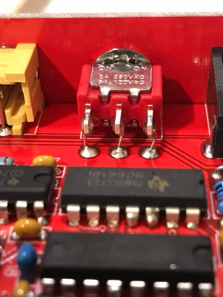
For the switch I’d just use a normal panel mount ON-ON mini (not sub-mini) toggle and use some old clipped resistor leads to connect it to the pcb. I’m pretty sure I used the substitution you mentioned for my first one or two Cadets, but it’s not a perfect fit… The legs are a tiny bit too short, so you have to put the switch in at a not exactly perpendicular angle to the front panel. It’s not a huge deal, and I’m not going to change mine, but on all the other Cadets and Castles I’ve built so far, I’ve just been using panel mount switches and I feel much better about it.
Example I saved from someone’s facebook post a while ago of how to do it with a panel mount switch (sorry forgot whose post!):
#3 — joem · 2019-01-22
The capacitor substitutions sound fine to me. The things to match when it comes to capacitors is value (obviously), general type (electrolytic vs MLCC), voltage, tolerance, lead spacing, and you might as well match the dielectric too. Looks like you got that right in all those cases.
And if those restrictions are too tight to find a substitution, the voltage, tolerance, lead spacing, and dielectric don’t always have to exactly match the spec’d part, they just need to be good enough, but knowing when they are often requires a bit of understanding the circuit:
- Most eurorack circuits will never deal with a voltage swing bigger than +12V to -12V (so 24V total) and often the way the capacitors are used in the circuits they’re not seeing that max swing, so often 25V or even 16V caps can be used, but not always.
- Tolerance of caps is like tolerance of resistors… higher tolerance is nicer but not always necessary depending on what it’s purpose is (though in video accurate caps matter a bit more than audio).
- Lead spacing won’t affect the way the circuit works at all (unless the spacing causes you to have really long leads), but it’s nice to not have to bend some 5mm-spaced leads to fit into 2.5mm-spaced holes and vice versa.
- And the dielectric doesn’t always matter either, though sometimes you don’t have much choice for a desired capacitance and tolerance and voltage combo.
#4 — Agawell · 2019-01-23
always try to buy as much as possible from the same supplier as possible - and from as few suppliers as possible - to reduce postage - so I’d either buy from mouser or digikey unless you can help it
substitutes for the capacitors at mouser - there seems to be an improved susbtitute finder at mouser - if you scroll down a bit you can tick what you need from the present spec and these just showed up first in the list and look ok to me
mouser switches are quite expensive - I got some from tayda, I’ve not used them yet, but had a bit of a play with them and they feel the same as the mouser ones - but about 1/5 the price or something
#5 — reverselandfill · 2019-01-23
Good tips!
I buy some thing from Ebay. free shipping .
Things like switches, certain potmeters and jacks can be very cheap.
#6 — Agawell · 2019-01-23
I always get my jack sockets from Thonk in batches of 50 - they’re nearly half the price - but Thonk shipping to NL is not cheap, so I always try to add a lot of things I can’t get elsewhere in too
thonk also have reasonably priced switches - well, cheaper than mouser at least!!
potentiometers are pretty pricey - must have a look at ebay - as I will need some (a lot) more soon
looking at tayda for some resistors - they have a page where you can pick and mix 1/4W metal film resistors for $0.012 each - pretty handy
shrouded headers are also cheap from tayda - $0.18 each both 16 and 14 pin
they also have a coupon code at the moment - search for the Tayda Days thread on Muffs - it’s updated as and when
pity they don’t do 0603 smd parts I need an extra 100nF capacitor
will check arrow they’ve been good for single parts with free shipping in the past!!! and they also have a sale at the moment!!
#7 — addamm · 2019-09-12
This feels like a silly question but can I use 3.9K resistors in place of the 3.92Ks in the sync gen? Also, for the 0r resistor - cool to just place a lowly old link in there? Thanks!
#8 — reverselandfill · 2019-09-12
yes you can use 3.9k (I think I did this too) btw: you can also measure the 1% resistors and see if there are some that are 3.92k
0r link is also a good option.
#9 — addamm · 2019-09-12
Great, thanks. That’s what I was thinking. I’m more likely to find some that are maybe a little on the higher end of the spec than I am finding any 20r resistors to bridge them in my stash

#10 — GijsvO · 2019-10-29
addamm wrote:
2K
Similar question about the 2.05k resistors on the Cadet VCO. Would 2k be okay? I measured all the 2k ones I’ve got (with a pretty cheap multimeter) and they’re all within 1.98k to 2.00k.
#11 — reverselandfill · 2019-10-29
I think it should be fine. If not, then you know where to look

Also, I used a normal 2k resistor at R43 instead of a tempco, as commented in the BOMMaybe @creatorlars can explain why the R25 (2.05k) is of that value?
#12 — transistorcat · 2019-10-29
Judging from a quick glance at the schematics, I’d guess this affects the triangle wave symmetry.
I can’t tell what a 2% change will do without crunching some numbers, but they are specified at 1% (so 2% is probably not a total failure).
I’m guessing you risk a visible asymmetry, but i’d be surprised if it breaks everything
#13 — creatorlars · 2019-10-29
R25 will effect pulsewidth IIRC. 2.05K was the closest E96 value that gave me closest to 50% pulsewidth.
#14 — GijsvO · 2019-10-29
Thanks all! I guess I won’t risk using a 2k then. Had another reminder today of how much I hate desoldering

.
#15 — JonasBers · 2019-10-29
That’s good to know. So a variable resistor there would give you an adjustable pulse width.
#16 — reverselandfill · 2019-11-11
I have a few questions about the matched transistor pairs in the VCO BOM:
1: what do these transistor pair do? (as I gather, something to do with exponential CV input tracking? / drift)
2: Why is this important for a video oscillator? (Is it that you could control several VCO’s in the same way without too much difference?)
3: What are the effects of non-matched pairs in this scenario?
In my own build I used non matched transistors (but from the same reel)
I’m building a system for somebody else now, so I want to be clear on these questions.
#17 — transistorcat · 2019-11-12
Q2A and Q2B are part of the exponential converter circuit.
Typically one of them does the exponentiation, and the other is used to compensate for temperature drift in the first one, so the degree of matching and the thermal contact between these will affect your tracking and offset over temperature.
What does a video oscillator gain from having an exponential response?
It lets a linear step in CV lead to a doubling in line density, which generally feels more “natural”.
It also means that if you have two osc’s set to different frequencies you can
modulate both together with the same signal while keeping the ratio between them static.
iirc, the castle clock osc does not have an expco, so if you have that you can compare.
They are absolutely less critical than in an audio module, since the ear is very good at picking up on small errors.
For what it’s worth, I’ve been thinking about trying to mod in a secondary linear input to one of my IX’s.
What happens if they’re not matched?
The tracking (i.e. how well a certain step in voltage correctly becomes a certain factor change in frequency) might change as the room or synth warms and cools. If your patches generally requires specific controlled frequencies or ratios, this will lead to you tuning a lot, while a properly compensated VCO is more a set and forget - type of deal.
Q’s 4A, 4B, 5A, 5B, are all part of the linear triangle VCO core, combining the output of the exponential stage with comparator output and driving the integrator cap.
I’m not entirely sure what bad matching here will do, but i’m guessing slight drifts and some amount of wave asymmetry.
#18 — reverselandfill · 2019-11-12
Thanks for the extensive explanation.
Did you thermally couple the transistor pairs, with thermal paste?
#19 — transistorcat · 2019-11-12
i bought about 2-3 times as many transistors as i needed, did a rough matching by forward voltage across the base-emitter, and then pushed them together on the board after soldering - i.e. i assumed that i would never use this as a main audio osc and was willing to live with any consequences.
I have yet to regret that decision, but i do still have an entire lifetime in front of me full of opportunities to do so.
#20 — reverselandfill · 2019-11-12
I was going to try the ian fritz method of matching. (not as extensive as he describes it though, with those double measurings.)
How did you do the ‘forward voltage / base emitter’ testing?
#21 — transistorcat · 2019-11-12
I just used a voltmeter in diode tester mode across the base and emitter of the transistor.
Some variation on the Ian Fritz method is probably a lot better.
#22 — brock · 2021-10-08
Lol, On the Cadet IV Dual Ramp can confirm that you can simply substitute two electrolytic capacitors in parallel (5 & 10uF) to make up for the fact you ordered parts from Mouser many months ago (except for that 15uF cap that was sold out!), finally got around to your project, and your partner wants extra ramps for her performance tomorrow.
#23 — Tim · 2023-01-20
joem wrote:
video accurate caps matter a bit more than audio
As accurate caps are especially important for video, my query is it possibly ok to error on the side of higher voltage rating for general application unless indicated, i.e. use 24 volt rated (as it will cover the -10v/+10v voltage swing? Or even say 50v/100v? Or should i abide to the specifics of the overall BOM? Cheers!
#24 — creatorlars · 2023-01-20
Tim wrote:
As accurate caps are especially important for video, my query is it possibly ok to error on the side of higher voltage rating for general application unless indicated, i.e. use 24 volt rated (as it will cover the -10v/+10v voltage swing? Or even say 50v/100v? Or should i abide to the specifics of the overall BOM? Cheers!
It’s good practice to rate three times the power rails for smaller caps at least. 1u or smaller, use 50V caps. Higher voltage rating only helps the cap maintain its nominal value under load.
#25 — Tim · 2023-01-20
thanx so much lars! <3
#26 — Tim · 2023-01-20
Also wanted to ask as all my searches have brought me to dead ends as seemingly obsolescence has taken hold, but any leads on where to source a XTAL OSC VCXO 13.5000MHZ CMOS? ooof so far zero luck. Cheers yall!
#27 — rempesm · 2023-01-20
Unfortunately there aren’t any readily available sources of that VCXO unless you buy in huge bulk.
Check out this thread: [Project] Sync Generator modification
#28 — Tim · 2023-01-20
alibaba.comhttps://www.alibaba.com/product-detail/BOM-Electronic-Components-Crystal-Oscillator-oscillating_1600222512160.htmlBom Electronic Components Crystal Oscillator Oscillating Xtal Osc Vcxo 13.5000mhz Cmos Csx750vcb13.500m-ut - Buy Csx750vcb13.500m-ut,Xtal Osc Vcxo 13.5000mhz Cmos,Crystal Oscillator Resonator Oscillating Product on Alibaba.com
Link: Bom Electronic Components Crystal Oscillator Oscillating Xtal Osc Vcxo...
Just stumbled upon this and requested a sample! Fingers crossed it’s all good. But whoah the reverse landfill adaptor board is a real neat work around! Need to read deeper into that one though, to get all the nuances and caveats.
#29 — rempesm · 2023-01-20
I am generally suspicious that any electrical components sourced from Alibabi are actually what they say they are (I’ve gotten several blacktopped counterfeit ICs before that were worthless) but hope it works!
#30 — Tim · 2023-02-15
Hey y’all, I am zeroing in on being done with the build, at least populating the PCBs and glorious fucking day I believe I found a 13.5 MHz VXCO SMD!! Gonna have to wait till March until it arrives but I just talked to the sales rep of the company and they have assured me that it is the right part. Fingers crossed! I also made mentioned that if they are a viable resource for this part that there are many nerds interested!! I will definitely report back when they arrive and I give a proper test!
Oh yeah, almost got too excited and forgot my question. My question is I literally am down to the last set of resistor values ( CADET 9 VCO module; ((r3, 8 and 25) and I’ve bodged one of them together to make an exact 4.02 K but have not zeroed in on the other 2… mostly getting a 4.01k value with the other Frankensteined resistors. Long walk for the question, but would 4.01k suffice. Thanks, y’all.
And yes, I know I can just buy them haha anyhoo cheers folks xo
#31 — reverselandfill · 2023-02-15
yes 4.01k should be fine
#32 — reverselandfill · 2023-02-16
unless you buy very precise resistors, there will always be some difference.
normal resistors used for video circuits have 1% tolerance