Cadet Sync Generator Problem
Category: Unknown · Tags: — · Posts: 55
#1 — tenshun · 2019-03-06
Hello,
I know LZX does not offer any help with the DIY projects but i figure i might as well ask for some help.
So i built the Cadet sync generator but for some reason i feel the atmega chip might not be programmed.
I connected the h and v outs to a oscope and seem to not get any 1 volt pulses.
I have it connected to the Cadet RGB encoder with the 14 pin sync cable.
I also have looked over the board for any missed solder connections.
any help would be great!
#2 — luix · 2019-03-07
can you try posting hires pics so we can see IC/diodes orientation, and we can do quick solder inspection?
my testing procedure is always is
-
if you have a bipolar power supply with ampmeter try see how much current your module is pulling, most of the time will be a short or bad orientation component the problem
-
if the pcb has microcontroller, try testing if it has the requiered power supply, in this case 5v.
-
check if anything gets too hot, you can do this by gently touching components (you can do this because its a lopower application) or use IP Alcohol.
-
check for bended legs of ICs
-
check for cold solder joints
thats at least a starter, its possible that everything is fine and as you said its just the microcontroller but we cant help if we dont get more details or info on your build
#3 — tenshun · 2019-03-07
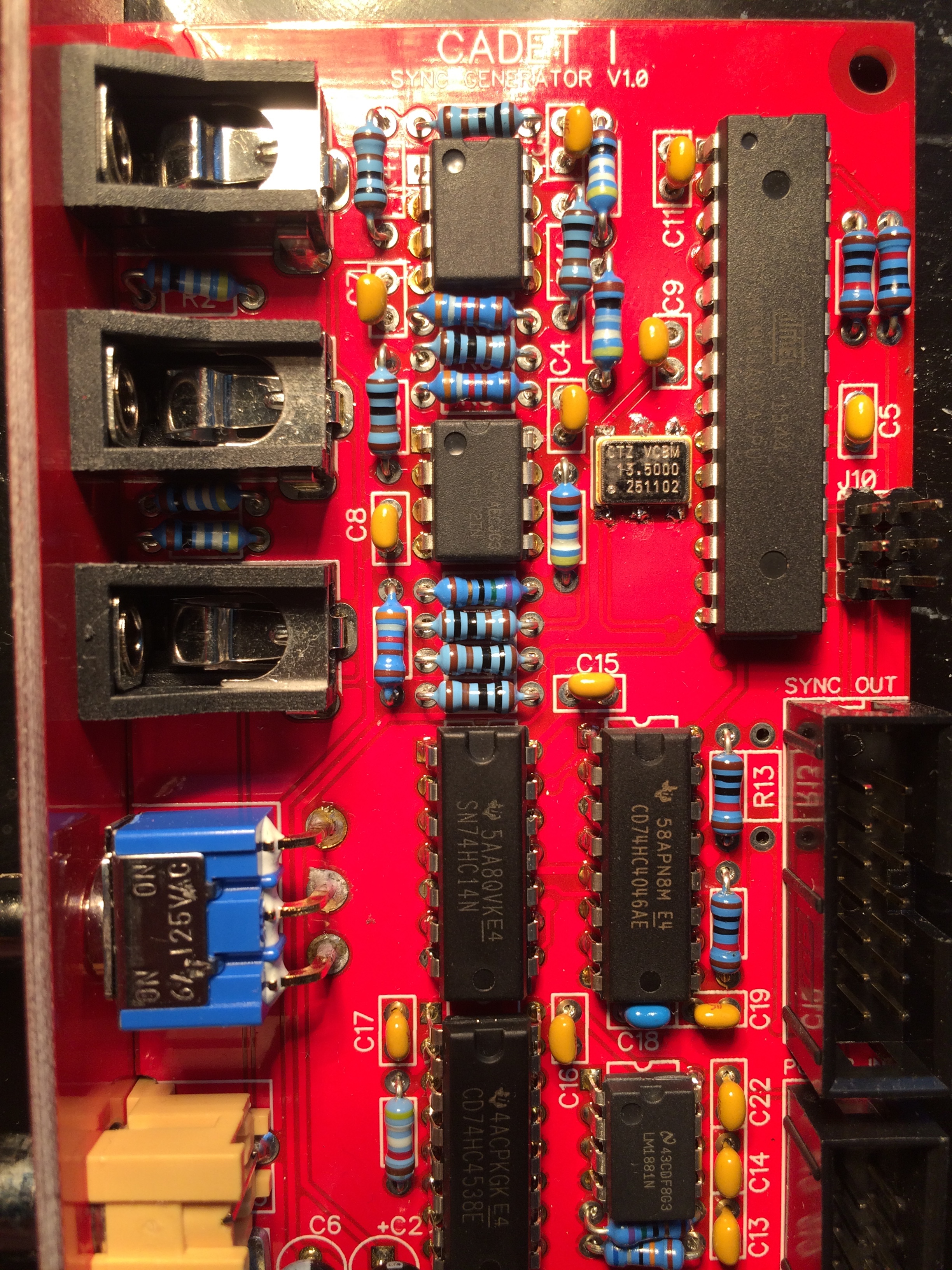
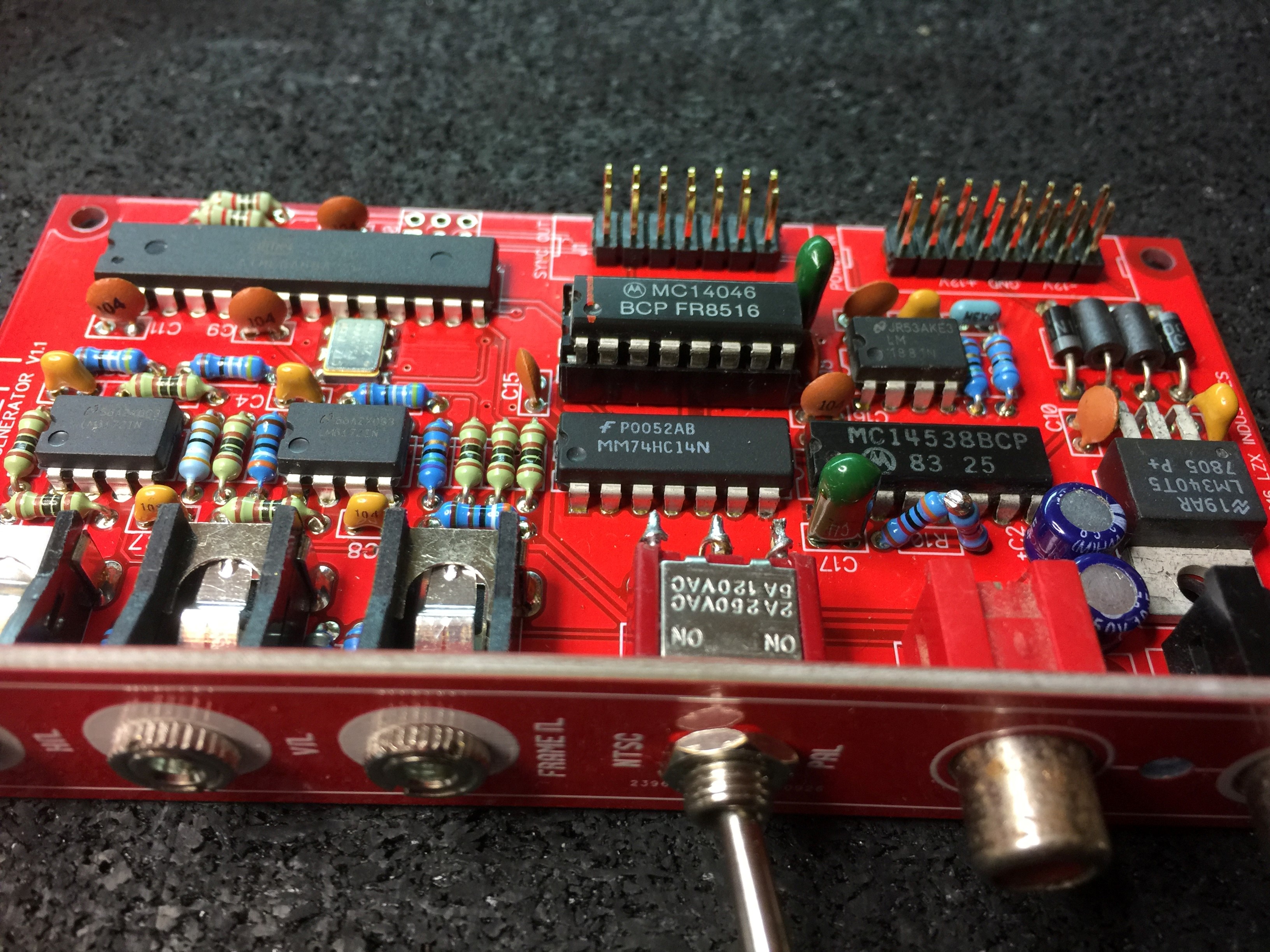
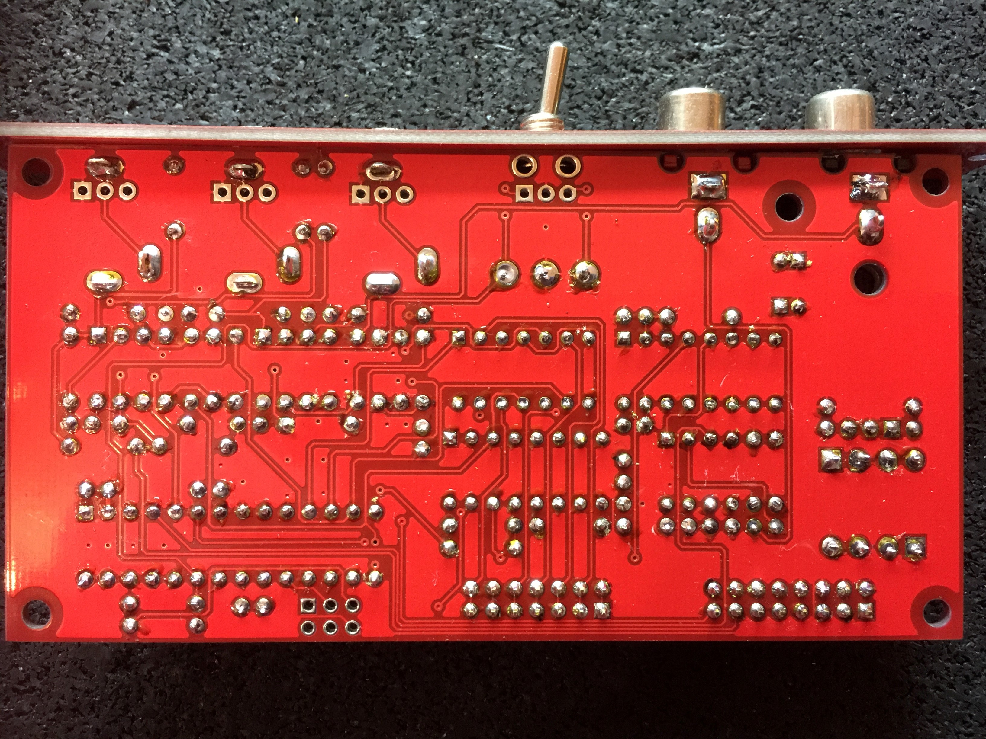
hello i have included some pictures.


#4 — reverselandfill · 2019-03-07
you have to connect r13! use a small wire or snipped off piece of a resistor leg.
note: in the future, use IC sockets.
#5 — tenshun · 2019-03-07
Thank you! i will connect it and see if it works out. i will post back with the results.
As for the ic sockets i think i remember something that they would not recommend the ic sockets due to noise interference or something like that?
#6 — reverselandfill · 2019-03-07
I thought that was only with the modules that use the TL1251, like the Fader
#7 — tenshun · 2019-03-08
so the bridge wire on R13 made it come alive!
thanks for eagle eye and help.
#8 — reverselandfill · 2019-03-08
it never hurts to help, like Spongebob says
#9 — joem · 2019-03-09
tenshun wrote:
As for the ic sockets i think i remember something that they would not recommend the ic sockets due to noise interference or something like that?
I think Lars recommends not using sockets with all the Cadet (and Castle?) stuff because the sockets can add a small bit of capacitance to these higher-frequency-than-audio-rate circuits. That said, I’ve used sockets on some of the builds and haven’t noticed much issues.
#10 — csboling · 2019-03-09
I’ve got some type of issue with my sync generator that’s causing it to fail to genlock. Everything else about the sync generator seems to work - I’m able to sync the ramp generator and RGB encoder over the sync bus as well as some Castle clock VCOs over the power bus, the 1V outputs work, and it’s buffering the RCA input to the RCA output fine.
The patch I’m working with is:
- Vidiot RCA luma output -> Cadet I input
- Vidiot 1V luma output -> Cadet II Red input
- To confirm that the sync bus is working, I’m also patching the horizontal ramp from Cadet IV to the Cadet II Green input.
- Cadet II video output -> display
The behavior I’m seeing is:
- The pattern from the Vidiot luma processor scrolls left to right, with a black gap every so often for the horizontal blanking interval.
- On an oscilloscope, I can see the separated sync from the video input arriving at the SIG_IN input (pin 14) and the generated sync from the ATMega arriving at the COMP_IN input (pin 3) of the 74HC4046AE PLL.
- I can measure 5V at the Vcc pins of all the 5V ICs.
- At the PH_COMP2_OUT pin of the PLL, I measure 0V.
- At the VC input pin of the crystal oscillator, I measure 0V.
Maybe I’ve just got a dead PLL? Makes using sockets in the future sound real appealing. Here are some photos, any thoughts or advice are tremendously appreciated.


#11 — reverselandfill · 2019-03-09
so you are syncing the sync generator with the vidiot?
what happens if you leave out the vidiot and only use the sync generator + ramps?
#12 — csboling · 2019-03-09
Yeah, with just the ramps on the sync bus patched to the RGB encoder the sync is fine, no “marching”. I also just discovered that if I patch:
- CCTV camera -> Cadet I input
- Cadet I output -> Cadet III video input
- Cadet III luma -> Cadet II Red in
as described in the Cadet I manual, it syncs to the camera! But replacing the CCTV camera with the Vidiot luma out, the image is still marching. Same if I connect Vidiot sync out -> Cadet I sync in and patch an oscillator from the Vidiot to the RGB encoder. Based on this post I was expecting these to work. However I can patch:
- CCTV camera -> Vidiot camera input
- Vidiot sync out -> Cadet I sync in
- Cadet I sync out -> Cadet III video in
- Vidiot luma out -> Prismatic Ray
and now everything in my rig is synced! However, disconnecting the camera input from the Vidiot makes the Vidiot and Prismatic Ray oscillators start marching again, so I guess that’s the most important thing, at least with my unit. The sync loop thru switch on the Vidiot hasn’t seemed to make a difference for any of the above scenarios.
#13 — Resonant_Space · 2019-04-05
Just built a Cadet Sync Generator, and having some issues.There’s no signal at all from the horizontal, vertical, and frame sync outputs on the front panel. I’m also seeing +5V on every pin of the sync bus (aside from GND). I was pretty careful with the build, and can’t see any obvious issues, but maybe I’m missing something. The 5V regulator is doing its job, and I measured +5V on the Vcc for all the chips, and a +22.5V difference across V+ and V- on the LM6172’s.
Here’s what I’m seeing out of the ATMEGA88A (received from LZX and presumably programmed)
Pin
1 5V
2 5V
3 0.744V
4 0
5 0.690V
6 0
7 5V
8 GND
9 2.556V
10 0
11 0.682V
12 0
13 0
14 0.685V
15 0
16 0.564V
17 0.612V
18 0.618V
19 0.619V
20 5V
21 0.574V
22 0
23 0
24 0.555V
25 0.555V
26 0.556V
27 0.555V
28 0.574V
Appreciate any advice or troubleshooting ideas. Thx!
#14 — Resonant_Space · 2019-04-06
Does anyone know what the output voltages would look like if the ATMEGA88A wasn’t programmed?
#15 — VisibleSignals · 2019-07-16
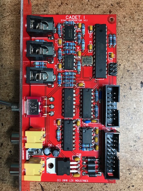
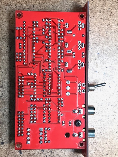
I am in a similar position to the above posters with my newly finished Sync Gen build - I am not seeing any sync outputs, just 5V DC on every relevant output pin of the ATMega.
My build is pretty clean (photos attached). R13 is soldered as a wire link. I see a clean 5V from the regulator, appropriate inputs and outputs on the LM1881 and 4538 pins, the 4046 is seeing the right input and the crystal seems to be generating an appropriate clock (admittedly measured with an old low bandwidth CRO so detail isn’t great at those frequencies).
It may be worth noting that I didn’t have a 74HC4046 to hand so I have tried with various other CD4046, MC14046, HEF4046 and HCF4046 instead, and they all showed the same behaviour (i.e. no output on the ATMega pins).
It seems to be a common question above, so “is it possible I have a blank ATMega chip?” Or do I need to use the specific 74HC4046 part rather than similar subs?
Thanks,
A.


#16 — creatorlars · 2019-07-16
Sounds like you have a blank Atmega chip. You can either load the firmware yourself (that’s what the 6-pin header on the PCB is for), send it to us to program it for you, or we can send you a burned chip. We had one batch escape earlier last year that had a few blank Atmegas in it.
#17 — Resonant_Space · 2019-07-16
Mine is still sitting on my bench–maybe it was one of the batch with the blank ATMEGA chips? It would be helpful if I could ship it to LZX to be programmed. Thanks.
#18 — creatorlars · 2019-07-16
Cool, just send in a support ticket to support@lzxindustries.net
#19 — VisibleSignals · 2019-07-17
Thanks Lars! I’ve splurged on a $4 ATMEGA88 USB programmer

#20 — brknfixie · 2019-07-21
Hi,
Troubleshooting my Cadet sync and after checking everything I’m pretty sure the firmware wasn’t loaded on my ATMEGA.
Have grabbed the firmware off github and I’ve tried programming it but getting the following error. Just wondering if I’m doing something wrong.
avrdude -c avrisp2 -p m88 -P com2 -e -U flash:w:LZX-C1-SW-V1.0.elf
avrdude: AVR device initialized and ready to accept instructions
Reading | ################################################## | 100% 0.06s
avrdude: Device signature = 0x1e930a
avrdude: erasing chip
avrdude: reading input file “LZX-C1-SW-V1.0.elf”
avrdude: input file LZX-C1-SW-V1.0.elf auto detected as invalid format
avrdude: invalid input file format: -1
avrdude: write to file ‘LZX-C1-SW-V1.0.elf’ failed
avrdude: safemode: Fuses OK
avrdude done. Thank you.
#21 — brknfixie · 2019-07-21
Oops was using avrdude 5.5 - updated to 6.3 and it works fine.
Module also working now!
FWIW I got this kit from Thonk 3 weeks ago so might need to check their kits
#22 — VisibleSignals · 2019-10-22
Update on my situation!
After many months of being too busy I finally took another look at this. I reprogrammed the ATMEGA chip and it verified OK. I replaced the 4046 with a 74HC4046 (exact part match). Unfortunately I’m still having no luck, so I’ve ordered another Cadet 1 board AND a replacement ATMEGA to try out in the original board, and will give that a go.
#23 — GijsvO · 2019-10-24
joem wrote:
As for the ic sockets i think i remember something that they would not recommend the ic sockets due to noise interference or something like that?
I think Lars recommends not using sockets with all the Cadet (and Castle?) stuff because the sockets can add a small bit of capacitance to these higher-frequency-than-audio-rate circuits. That said, I’ve used sockets on some of the builds and haven’t noticed much issues.
Could you please clear this up for us, @creatorlars? I’d very much prefer using IC sockets for repairability, but wouldn’t want performance to suffer.
#24 — reverselandfill · 2019-10-24
I have some minor issues with interference, especially with oscillators and hard keyers.
Although a better power supply helped a lot with these.
#25 — GijsvO · 2019-10-28
I have a problem with my video input (Cadet III into Cadet I) that looks similar to @csboling’s issue. Was that problem ever resolved? My patch is:
- DSLR camera through HDMI2AV box into Cadet III RCA Input.
- Cadet III RCA Output to Cadet I RCA Sync Input
- Cadet III Luma Output to Cadet II R/G/B
The camera image is slowly scrolling horizontally, at a rate of not even half an inch per second. Now, the weird thing is that if I patch a ramp from Cadet IV to another output of Cadet II, the ramp does not move. I find this weird, because it’s my understanding that the camera is now providing the master sync and if that sync is off, I expect everything to be off! I can also sync my Prismatic Ray to stay perfectly still in this same patch.
In another possibly related issue, my Prismatic Ray can’t seem to be synced through the RCA cable from Cadet I, whereas it works perfectly using the patch cable sync connection.
Does anyone have any suggestions about what could be wrong and what I could try?
#26 — reverselandfill · 2019-10-28
first input into the sync generator, then into the video input
so: camera -> Cadet I sync input -> Cadet I sync output -> Cadet III input
#27 — GijsvO · 2019-10-28
Awesome, that works @reverselandfill!
So my Cadet I RCA sync output is working correctly. And if I now connect the Cadet III Video Output to Prismatic Ray’s backside RCA input, it syncs correctly too. So why then does PR not sync this way when I have no camera connected and Cadet I is the master sync?
UPDATE: Strangely, after having synced momentarily, the drifting happened again. I can now report that the Hdmi2AV box is the likely culprit, because I get perfect sync from dvd players into my Cadets.
#28 — csboling · 2019-10-28
In my case I am able to sync the Cadet system to a camera (which outputs composite directly, not sure if the HDMI converter box could be a factor) but not to the Vidiot: Cadet I does not seem to be able to lock to sync generated by my Vidiot. If I patch the camera through the Vidiot this also works, Vidiot can lock to the camera sync and this gets passed through to the Cadet system.
GijsvO wrote:
my Prismatic Ray can’t seem to be synced through the RCA cable from Cadet I
As I recall from the schematic this RCA jack doesn’t output the sync generated by Cadet I, it is just a buffered copy of the signal going into the Cadet I RCA input if any. That’s all the Cadet III is doing too, and for me either configuration (camera → Cadet I → Cadet III OR camera → Cadet III → Cadet I) works. Edit: okay, I guess I don’t understand why one of these would work but not the other in some cases. A little latency from going through the extra buffer before the genlock circuit?
#29 — GijsvO · 2019-10-28
csboling wrote:
As I recall from the schematic this RCA jack doesn’t output the sync generated by Cadet I, it is just a buffered copy of the signal going into the Cadet I RCA input if any.
Bingo, that explains everything. Thanks for your quick help!
#30 — VisibleSignals · 2019-11-14
Well… an update from me. I bought a brand new Cadet 1 Sync Generator (from LZX direct) and built it up - and it has exactly the same issue as my first one, +5VDC on every sync output pin, with a little bit of colour carrier visible as well. I am disappoint

This time I socketed the ATMEGA… so I’ll get in touch with LZX directly and see if maybe I got unlucky again and got another blank one!
#31 — VisibleSignals · 2019-11-27
Hello all,
Sadly both of my Cadet 1s are still non-working, and as LZX don’t offer support for their DIY products (I emailed a few times, but given the price of the DIY that’s fair enough) I’m out of options other than to ask the community for help. Would someone be willing to program an ATMEGA88 with the Cadet 1 firmware and send it to me? Happy to pay for your time, the chip and postage… I’d just like to get a working sync so I can test the cadet 2 and play with all the other cadet modules I’ve already built up! As much as it’s fun checking their outputs on a scope, it would be nice to get some actual video output too
Thank you!
#32 — Agawell · 2019-11-27
If the atmega is the issue (ie not pre-programmed) then lzx will replace this … as it was a product fault… there was a batch that weren’t programmed at thonk that I know of… search on here for more details
#33 — transistorcat · 2019-11-27
A few things to try/check:
- Run another verification of the firmware image with your programmer tool. Make sure it fails if you disconnect the tool from the board.
- Read out the fuse bits from the atmega with the tool. depending on byte order in the programming software, these should be CE-DF-F9 or the reverse.
#34 — Vdot · 2019-11-27
Hey so I think i have the same problem and I’ve noticed that the Cadet 1 is syncing to my LZX Vidiot IF I have a camera plugged into it. Is it possible that the sync-strip abilities are unaffected by the Atmega chip? As a temporary solution maybe try connecting a video source into the RCA sync input of Cadet one and see if that works? As mentioned by Agawell, LZX did chime into this discussion and suggested the possibility of returning the unit to them so they can program the chip and that’s what I’ll probably do once I can take a brake from having fun.
#35 — VisibleSignals · 2019-11-27
Thanks for your responses guys,
Agawell:
When I bought my second Cadet 1 I asked if a replacement ATMEGA for my first one could be included in my shipment, and they said it would be, but unfortunately it wasn’t. After I built the second Cadet 1 it had the same problems as the first - all the signals look good up until the ATMEGA, but there’s nothing useful coming out. I then emailed support and sales a couple of times about it, and to ask if there was some debugging I could do (e.g. check pin voltages to see if any differed between programmed and non-programmed ATMEGAs) but they haven’t responded. As Lars wrote recently in the 2020 post, they essentially make no margin on DIY and don’t offer support, so I really can’t hold them at fault for that in any way. It’s difficult for me since there are no other DIY video guys who have Cadet gear anywhere near me (possibly not even in the rest of Australia, as far as I’m aware) to compare electronics with and try things out. And postage costs to here are ridiculous.
transistorcat:
I will try these things, thank you.
Vdot:
I’m using an expensive Extron test signal generator (set to colour bars) as my sync source, and I’ve tried numerous other devices: VCRs, vintage 70s sync generator, CFOG Video Equations - all with no luck. I even tried NTSC from the test signal generator, just in case it was an issue with PAL. The LM1881 is doing its job well; I can see good signals on its output pins.
What a sob story eh?
#36 — GijsvO · 2019-11-28
I can understand that they wouldn’t offer build support, but I would expect the contents of the package to match what’s being advertised. If they promised a programmed ATMEGA and it turns out to be blank, then I think LZX should correct that mistake.
#37 — VisibleSignals · 2019-11-28
Because I don’t know for certain that the ATMEGA is at fault, I’m hoping someone can program one for me so I can test it out and make sure. Alternatively, if there are any differences between the pin voltages on the pins on a working vs. non-programmed ATMEGA that might give me another way to be more sure. And on the plus side, if I do get a new ATMEGA and it works then I won’t need to hassle LZX for a replacement one!
I don’t want to make my problem into Lars’ problem - he does so much for the video synth community that it would be grossly unfair of me.
#38 — transistorcat · 2019-11-28
To expand on my line of question, the AVR is supposed to generate a sync if no external source is present, and there is very little between the AVR and the output.
If the AVR was correctly programmed and clocked, i’d expect you to see the sync signals (with a proper trigger and scope) on the sync bus.
If the fuses are set as the elf file wants them (and knowing nothing of your tool or what software you used, this is not certain), a missing clock would lead to you not being able to access the device with the tool after first programming it.
Unless i’m missing something obvious, it doesn’t sound like there are that many ways to break this that will allow you to reach the avr trough the programming interface but still completely fail to get any output out of it
#39 — VisibleSignals · 2019-11-28
Thanks @transistorcat! That’s hugely useful. I thought the ATMEGA was there to produce sync signals not natively supported by the LM1881 (for which it seemed to be grossly overqualified!) Knowing that the ATMEGA ought to be self-generating sync signals when the LM1881 has no composite input is useful - since they aren’t on either of my units.
I’m using a cheap usbasp programmer, from a Windows VM running on a Mac since my (work) PC is locked down and I can’t install the necessary drivers. So it’s entirely possible I failed when trying to reprogram the ATMEGA (although it claimed success and passed the checksum verification). I used basically the command line provided by brknfixie above:
avrdude -c avrisp2 -p m88 -P com2 -e -U flash:w:LZX-C1-SW-V1.0.elf
I changed the port and programmer type for my unit. The first time I had the programmer header in backwards and it failed, but when I had it plugged in correctly it claimed success
#40 — csboling · 2019-11-28
VisibleSignals wrote:
produce sync signals not natively supported by the LM1881
The LM1881 is a sync separator, its function is to extract sync from a composite signal and I don’t believe it can generate sync on its own.
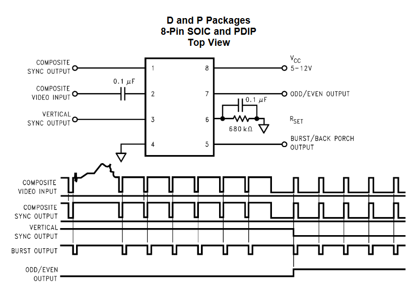
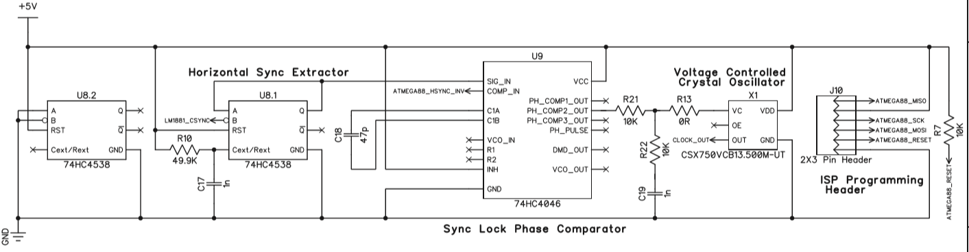
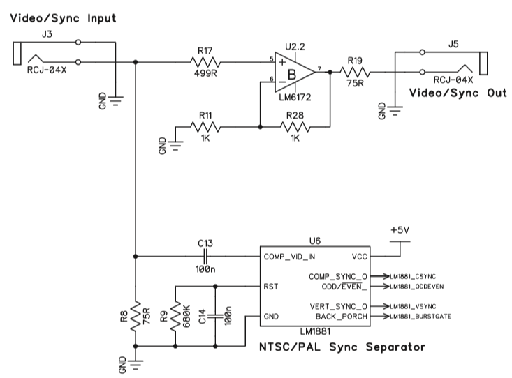
In the Cadet I the extracted sync components are used by the ATMEGA to derive vertical sync and odd/even clock signals. The horizontal sync then is extracted from the composite sync signal using a 74HC4538 multivibrator IC, and has its phase compared to the hsync signal generated by the ATMEGA. The phase difference goes through a passive lowpass filter, then is used to modulate the frequency of a crystal oscillator, which acts at the master clock for the ATMEGA. This creates a feedback system that’s a type of phase-locked loop which ensures that the ATMEGA’s horizontal sync tracks exactly the frequency and phase of the incoming sync signal. This way the ATMEGA generates the horizontal sync, vertical sync, etc. at all times. This design is described in more detail in the “Circuit design notes” section of the manual, right after the schematics.
The only output from the Cadet I that’s not generated by the ATMEGA is the RCA output, because this is just a buffered copy of the input signal. This is useful for taking a camera signal and deriving sync from it while passing the unaltered signal off to some other part of your rig for processing.
Sorry to hear this has been giving you so much trouble! As others have said if you’re able to program the ATMEGA at all, and you’re otherwise seeing good signals on the scope, you’re probably almost there. Here is the command line that worked for another builder – it looks like your command line is missing the fuse settings. Lars posted a screenshot of the required fuse settings in the post right above that. I’ll submit a pull request to the LZX firmware Github with this command line, hopefully that makes it easier to find.
#41 — VisibleSignals · 2019-11-28
Thanks @csboling. From your link it looks like this is the command I should have used, with fuse settings:
avrdude -V -p m88p -c usbasp -P usb -B 1 -U flash:w:LZX-C1-SW-V1.0.elf -U efuse:w:0xF9:m -U hfuse:w:0xDF:m -U lfuse:w:0xFF:m
I’ll try this tonight.
#42 — VisibleSignals · 2019-11-28
transistorcat wrote:
CE-DF-F9
@transistorcat these are the fuse settings you’ve given a couple of times, but Lars’ post says FF-DF-F9 (or F9-DF-FF). Can you tell me what the difference between your settings and Lars’ is?
#43 — VisibleSignals · 2019-11-29
Good news, my Cadet 1 is now generating good-looking sync!
I will write more about what I learned soon.
TL;DR I needed to set the fuses, and avrdude was confusing things by reading back efuse as 0x01 even though it had set it correctly!
#44 — transistorcat · 2019-11-29
Those were the fuse settings i read from the .elf file when i ran ‘readelf LZX-C1-SW-V1.0.elf -x .fuse’
Both the ‘FF’ and the ‘CE’ will set the clock source to external, but the CE will allow for a few ms more of settling time before running.
I’m guessing either works, especially since the cadet has not just a crystal but a full oscillator.
#45 — GijsvO · 2019-11-29
That’s great news, Aladan!
#46 — VisibleSignals · 2019-12-05
Executive Summary: the fuses need to be programmed correctly!
Notes:
- I used a super-cheap ‘usbasp’ programmer
- I used an old Mac which had the Arduino app on it
- In MacOSX, applications are a type of folder so in a command window: cd /Applications/Arduino.app/Contents/Java/hardware/tools/avr/bin/
- That folder has the avrdude program in it
-
I used these flags (upper case and lower case are different so type them exactly!):
-
programmer (-c usbasp) and port (-P usb)
- avrdude.conf file explicitly with -C option
- correct part number -p m88 (NOT -p m88p like someone wrote somewhere)
- -B 1 something to do with timing
- -U efuse:w:0xF9:m -U hfuse:w:0xDF:m -U lfuse:w:0xFF:m to program the three fuses
- -u to tell it to ignore when the efuse doesn’t verify correctly (see below)
- -U flash:w:LZX-C1-SW-V1.0.bin to program the actual flash image (see below - this is not the .elf file!)
The biggest learning for me was that the .elf file is a container with various data inside it. Mostly it’s the actual flash binary, but my avrdude program couldn’t read .elf files directly, so I had to use avr-objcopy first to extract that binary image into another file.
These links were helpful:
https://www.avrfreaks.net/forum/help-avrdude-and-fuse-program-elf-fileHi all.. I've used lock.h and fuse.h for include fuse configuration in my c code. [code:1] #if defined A FUSES = { .low = 0xFF,
Link: help with avrdude and fuse program from elf file.
https://helpmanual.io/help/avr-objdump/As well as the binary the .elf file has the fuse settings in there. I used avr-objdump to dump out the entire contents of the .elf file to see what they should be set to.
When avrdude verifies the efuse values it has just written it gets back a different value. I program it as “0xff” but it gets back “0x01”. That’s apparently quite OK, which is why the -u flag is required to tell avrdude that it’s OK that it appears to have failed. This calculator was helpful: http://www.engbedded.com/fusecalc/
It says: " * Note that some numerical values refer to fuses containing undefined bits (set to ‘1’ here). Depending on the target device these fuse bits will be read either as ‘0’ or ‘1’. Verification errors will occur if the values are read back with undefined bits set to ‘0’. Everything is fine if the values read from the device are either the same as programmed, or the following values (undefined set to ‘0’): Extended: 0x01 ."
Also, I had the programmer plugged in backwards the first few times (doh!)
If you can use a GUI program instead of the command line I suspect things will be much easier and you won’t need to know all that stuff above, but sadly I don’t have a computer that I could install one on to.
Also note that you can program the fuses and flash separately, one at a time, with multiple calls to avrdude. That was helpful as I could see that hfuse and lfuse were successful, then work on efuse and the flash image separately until I got them to work.
Here are some command lines I used.
Change into the avrdude program folder:
cd /Applications/Arduino.app/Contents/Java/hardware/tools/avr/bin/
I copied the LZX elf image file into that same folder, for convenience.
Dump the .elf file contents to see the fuse values:
./avr-objdump -s LZX-C1-SW-V1.0.elf
Extract the flash image into a separate file:
./avr-objcopy LZX-C1-SW-V1.0.elf -O binary LZX-C1-SW-V1.0.bin -j .text
Flash only:
./avrdude -c usbasp -p m88 -P usb -B 1 -U flash:w:LZX-C1-SW-V1.0.bin -C …/etc/avrdude.conf
Fuses:
./avrdude -c usbasp -p m88 -P usb -B 1 -U lfuse:w:0xFF:m -U hfuse:w:0xDF:m -U efuse:w:0xF9:m -u -C …/etc/avrdude.conf
Just the efuse on its own:
./avrdude -c usbasp -p m88 -P usb -B 1 -U efuse:w:0xF9:m -u -C …/etc/avrdude.conf
This shows the fuses being programmed, along with the efuse verification error which you can safely ignore:
avrdude: set SCK frequency to 750000 Hz
avrdude: warning: cannot set sck period. please check for usbasp firmware update.
avrdude: AVR device initialized and ready to accept instructions

Reading | ################################################## | 100% 0.00s

avrdude: Device signature = 0x1e930a
avrdude: reading input file "0xFF"
avrdude: writing lfuse (1 bytes):

Writing | ################################################## | 100% 0.00s

avrdude: 1 bytes of lfuse written
avrdude: verifying lfuse memory against 0xFF:
avrdude: load data lfuse data from input file 0xFF:
avrdude: input file 0xFF contains 1 bytes
avrdude: reading on-chip lfuse data:

Reading | ################################################## | 100% 0.00s

avrdude: verifying ...
avrdude: 1 bytes of lfuse verified
avrdude: reading input file "0xDF"
avrdude: writing hfuse (1 bytes):

Writing | ################################################## | 100% 0.00s

avrdude: 1 bytes of hfuse written
avrdude: verifying hfuse memory against 0xDF:
avrdude: load data hfuse data from input file 0xDF:
avrdude: input file 0xDF contains 1 bytes
avrdude: reading on-chip hfuse data:

Reading | ################################################## | 100% 0.00s

avrdude: verifying ...
avrdude: 1 bytes of hfuse verified
avrdude: reading input file "0xF9"
avrdude: writing efuse (1 bytes):

Writing |                                                    | 0% 0.00s ***failed;
Writing | ################################################## | 100% 0.03s

avrdude: 1 bytes of efuse written
avrdude: verifying efuse memory against 0xF9:
avrdude: load data efuse data from input file 0xF9:
avrdude: input file 0xF9 contains 1 bytes
avrdude: reading on-chip efuse data:

Reading | ################################################## | 100% 0.00s

avrdude: verifying ...
avrdude: verification error, first mismatch at byte 0x0000
         0x01 != 0xf9
avrdude: verification error; content mismatch

avrdude done.  Thank you.
Thank you to everyone who helped, particularly transistorcat and csboling.
#47 — addamm · 2021-01-10
Hi all, built this a while and can’t seem to figure out my issue. I’m doing cctv camera -> Cadet I input// cadet I output -> cadet III input /// then if I take the rca output from cadet III into my video capture it looks ok (just as if I plug my camera direct into cadet III and take the video straight out). But if I take the luma out into Cadet II I get a horizontally scrolling image on any input (I have the 14 pin cable connected).
If I take the horizontal or vertical syncs from the cadet I out into a function generator (Maths in this case) and then back into one of the RGB encoder inputs I do get horizontal lines so the sync generator is doing something…
Anything I can measure (voltages on the atmega) to tell if I need to flash the chip or any other ideas? I can post pics if that helps but I think it’s a clean build. Thanks!!
#48 — VisibleSignals · 2021-01-10
Hi Adam,
The ‘video out’ on the Cadet III video input is actually just a buffered copy of the video input, so it’s almost always going to work just fine (the same is true of the video output socket on the Cadet I sync generator).
However, if you use the luma output of the Cadet III video input and put it into a Cadet II encoder which isn’t properly synchronised to the input signal of the Cadet III (by the Cadet I sync generator) then you’ll get exactly the behaviour you’re describing. Basically the Cadet I is generating a clock which the Cadet II is using, but it’s not quite in sync with the Cadet III input, so the two tend to drift slightly on the screen compared to each other.
You can use a scope to see if there’s a sync signal on the 14 pin connector, which there almost certainly is you’re actually seeing output from the Cadet II encoder. With no sync the encoder doesn’t produce any output signal at all. But unfortunately I don’t think there’s any simple way to tell if the atmega is following the external video input or generating it’s own internal sync, other than implicitly by looking for the out-of-sync behaviour you’re seeing.
My suggestion is to try a few different input sources, and see if you can find one that works correctly. For what it’s worth (keeping in mind I use PAL exclusively) I’ve found that my Cadet I encoders occasionally struggle with some signals (especially those from VCRs) but it’s often not predictable which ones it won’t like. I’ve often found that putting the input signal through a scaler, TBC, video mixer, or even a just distribution amplifier before the Cadet I input can help it to sync better.
#49 — addamm · 2021-01-11
Thanks for the reply, aladan! Ah, that is a bit of a bummer. I don’t have much video gear at all but I think I tried every combo between my Cadet I-III, Syntonie CVB module, and Reverse Landfill triple function generator and don’t get a proper sync’ed signal when running through the cadets (side scrolling and it also appears in triplicate spaced apart horiztally). If I run signal into Cadet I and RCA out of Cadet III into the CVB and into Cadet II encoder I was getting a sync’ed signal but that was with the sync ribbon cable disconnected (because, as I understand it, the CVB does not require syncing), which sounds like further proof that the Cadet I is working, just not in the way I’d hope


I have a VCR that is a little tricky to get in the same room as my modular but I’ll give that a go - though I vaguely remember having the same issue a few months back when I tried that. Maybe I’ll look into an hdmi to composite converter just to try something else.
I’m running the modules off a tiptop uzeus and have some cheap RCA cables - could either of those things possibly be contributing to the sync issues?
#50 — Fox · 2021-01-11
Can you tell us about your CCTV camera? What resolution does it output?
#51 — addamm · 2021-01-11
I honestly have no idea. I bought it for nothing off a guy in town who does editing and has a video store (!) - it’s used or older, and the only label on it says “B/W CCTV Camera”, the lens is Computar 8.5mm 1:1.3 (my apologies for very obviously knowing very little about this stuff). It runs on 24v and now that I’m looking at it it has a trimmer labeled “line phase” which I have not messed with.
#52 — VisibleSignals · 2021-01-11
Make sure you set the PAL/NTSC switches correctly for that camera.
Might be worth trying to hook up with another video enthusiast in your area to see if they can help out with more gear to help debug, if you can?
I don’t think cheap RCA cables would cause the problem, but I guess it’s possible. I don’t know anything about the power supply you mention, sorry.
#53 — addamm · 2021-01-11
Thanks again. I did try with both NTSC and PAL switches on the cadets just for the heck of it.
Will look into an alternative video source to try out.
Edit to add: I tried the vcr/dvd player and all seems to be working. Good news, but a little embarrassing I didn’t try that before posting

#54 — Rik_bS · 2021-01-13
Ahhh, I have been told that DVD players generally have a decent quality output so they are good for testing with
#55 — addamm · 2021-01-14
Yeah this was just a very cheap, very used dvd/vcr combo unit. I tried connecting the security camera to the video input on the vcr side but without the remote I’m not sure there was a way to switch to the vcr input (and no universal remotes in the house). Still curious if that would work. Anyway, here’s a still of my production of Neubauten Under the Sea!