Cadet II Encoder Troubleshooting Help
Category: Unknown · Tags: — · Posts: 36
#1 — Whelm · 2019-12-31
Hello folks. I’m hoping to get some guidance on trouble shooting my cadets. I have moderate experience in euro DIY but this is my first foray into visual which makes the trouble shooting a bit trickier for me, and I wasn’t good at it to begin with.
I built a Cadet 21 type setup. By the time I had the case ready to go, I already had all the modules built up, which I realize isn’t great from a trouble-shooting perspective. I was expecting trouble, but what I am getting is absolutely no output at all. By no output I mean on the screen - I’m registering about 1.7V on output 1 and 0.7 on output 2. TVs do not recognize an incoming signal.
I’ve stripped it down to everything but the sync generator, the RGB encoder, and oscillators. The oscillators appear to be working, and I have patched them into the RGB inputs, but I can get neither of two TVs tested to recognize any signal coming through the RCA from the encoder.
Sadly I do not have an oscilloscope. I checked the 7805 and the voltage seemed normal. I’m hoping someone here can give me some guidance on what other voltages I can check and perhaps what readings I should expect, or where I might focus my attention.
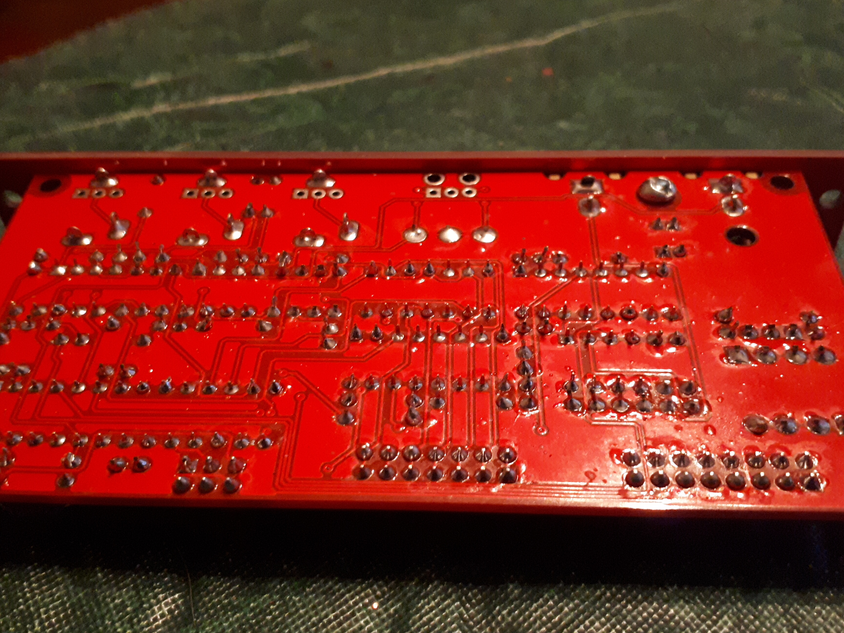
I’ve gone over the soldering, but it is difficult to trace the circuit from the schematic without knowing the layout of the components on the board. I’ve checked the polarity of all the components.
Any tips or suggestions are much appreciated! Cheers.
#2 — csboling · 2019-12-31
How are you testing the oscillators? Patching them to your other Euro stuff? I would guess that the VCOs still work when not receiving sync, but you may be able to check that sync is working without a scope by experimenting with the oscillators. For example by putting the VCOs in vertical range and flipping the sync switch, it should switch between a plain triangle wave and one that’s hard-synced to the field rate (60 Hz for NTSC / 50 Hz for PAL). This should sound different enough to allow figuring out if your sync generator is working correctly.
In my experience if the RGB encoder is not receiving sync, displays won’t register it at all - on my display I would get a solid blue “no input” screen, same as if I just disconnected the AV input. If you get a blue screen or “no input” indication when nothing is connected, but get a black screen when connecting to your RGB encoder, your encoder may be outputting sync but not encoding signals correctly (due to a bad solder joint / whatever).
If you are getting sync generated, I would guess you can also listen to the front panel vertical sync output to get a very low tone (50-60 Hz pulse wave) and a tone from the hsync output that may be too high-frequency to hear (>15 kHz). If you’re not getting sync output from Cadet I at all, but you don’t think there are any soldering issues or incorrect components, it might be worth trying to reprogram the microcontroller (though this will require an AVR programmer). Some discussion of the settings for doing this is here.
#3 — Whelm · 2019-12-31
Hey, thanks for the input. It seems you’re right about the sync being the issue. I “tested” the oscs just by listening to them. Horizontal is very high but audible for much of the range, vertical is not what I would call “very low”, but much lower than horizontal. However flipping the sync switch has no effect on any of the oscillators. Which I guess means I need to switch my attention to the sync generator! I’ll see what I can discover with my multimeter there this afternoon.
#4 — csboling · 2019-12-31
Whelm wrote:
Horizontal is very high but audible for much of the range, vertical is not what I would call “very low”, but much lower than horizontal.
Yes this sounds right, what I meant is that a working sync generator’s front panel outputs will also be audible if you patch directly from the “HΠ_” (very high pitched), “VΠ_” (square wave sound), or “FRAMEΠ_” (lower pitched square wave) outputs.
On listening to them you’re right that none of these sound “very low” as you get a lot of upper harmonics from the pulse waves. With the VCOs in vertical range but with sync off, I can hear a clean triangle wave that sweeps smoothly as I sweep the frequency knob. With sync engaged there is a buzzier tone and a pleasing sweep in harmonic content as I sweep the knob.
Best of luck with troubleshooting your sync gen! Aside from checking the power pins on the ICs, you may be able to check some functionality by setting your multimeter to frequency measurement mode.
#5 — rempesm · 2019-12-31
If you’re confident your soldering on the sync generator is good, I would definitely check that the Atmega chip is programmed. I had a similar issue with either extremely erratic or no output in my system until I narrowed it down to that. The thread csboling referenced has good info, particularly on setting the fuses correctly.
#6 — Whelm · 2020-01-02
Well I wouldn’t say I’m confident but I’ve traced the circuit now and as best as I can tell the soldering is good. I did actually find a couple jack lugs that I had missed but fixing that hasn’t changed the problem. It does though make me think it’s more likely something I fucked up than that the atmega isn’t programmed.
I don’t have a programmer and have zero experience programming microcontrollers. Is there a way to verify whether the atmega is programmed? I feel like I’m about as likely to break the thing as I am to fix it and would rather not get into that territory unless I’m quite sure that’s the issue.
EDIT: just read this thread which suggests it may be difficult to verify the atmega without a scope… Perhaps I will need to order up a programmer.
I read the power pins on the ICs and everything seems normal, as far as I can tell:
lm6172 (U1)
VC+: 11.19
VC-: 11.3
LM6172 (U2)
VC+:11.19
VC-: 11.3
SN74HC
Vcc:5.05
CD74HC
Vcc: 5.05
74HC4538
Vcc: 5.05
Atmega88
Vcc: 5.05
lm1881
Vcc: 5.05
#7 — reverselandfill · 2020-01-02
I was building 2 Sync generators. both Atmega’s were blank. I got send new ones, unfortunately those were blank too. (I have 1 older sync generator that works, so I can check the pcb’s)
So the possibility of this happening to you is high.
#8 — rempesm · 2020-01-02
I don’t have my board in front of me to compare but nothing is jumping out at me as an obvious issue. My issue was similar in that my soldering was fine but the Atmega chip was blank. If you can find someone local to you who has access to an AVR ISP MKII programmer and a PC running Atmel Studio 7, that’s probably your best bet.
If you want to try it on your own, I used this programmer and once I got the settings correct in Atmel Studio based on the thread csboling linked before, it was really quick to upload to the Atmega chip: https://www.amazon.com/gp/product/B00KM6ZA9I
Keep us posted!
#9 — Whelm · 2020-01-02
Okay cool, thanks for the input everyone, I really appreciate it. I live in the boons so I’ll have to order a programmer and figure how to flash the chip. I run Linux which I’m sure will add another delightful layer of complexity.
I’ll let you know how that goes!
#10 — VisibleSignals · 2020-01-13
Hi @Whelm,
+1 for the unprogrammed ATMEGA. LZX sent me two blank ones too, on orders six months apart.
Programming is non-trivial if you haven’t done it before - I hadn’t and it took me a while to work out how to get everything right. And I’ve been a computer programmer since 1986!
But… it is very easy once you get all your ducks in a row.
If you are in the Australian or New Zealand “boonies” and would like me to program one for you, test that it works and then send it to you then please let me know and I’ll be happy to do so - I have a spare ATMEGA chip I bought while getting mine going.
Here’s the thread outlining my experience: Cadet Sync Generator Problem
Stay in touch because I’m here to make sure you don’t have the frustrating experience I did!

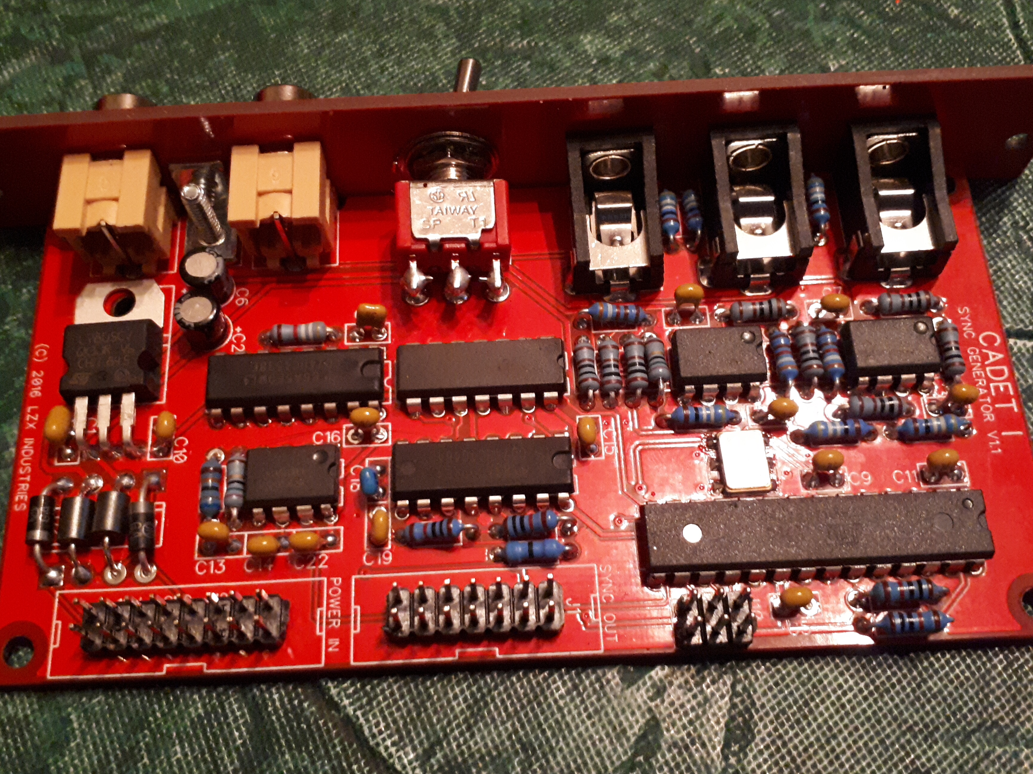
#11 — VisibleSignals · 2020-01-13
P.S. Your soldering looks pretty good, other than one pin on the IC in the top right corner (near the voltage regulator, third pin from the right on the bottom row of pins) which might be worth a quick check.
#12 — Whelm · 2020-01-13
Hey, thanks for the offer, but I’m all the way in Canada. I’m waiting on a ATMEGA programmer to arrive in the mail over the next couple of weeks. Hopefully I can figure it out based on your thread and a couple others that have been posted. I’m no programmer but I do have some experience flashing packages onto phones and shit so… fingers crossed.
That’s a drag you had such a frustrating experience. =/ You’ll definitely be hearing from me if/when I get lost.
It’s disappointing that this issue seems so prevalent, given the number of people who have had multiple chips sent unprogrammed. I really appreicate LZX providing these boards and schematics to the DIY community with little financial incentive for themselves but still, this seems to have affected more than a couple chips.
#13 — VisibleSignals · 2020-01-13
The way I see it I learnt more about programmings AVRs by hand (rather than just using the Arduino app) so it was a win in the end
#14 — sumawave · 2020-01-14
Hi,
I can tell you my case. It was due to the RGB encoder AD724JRZ’s defect. That is pre-soldered on the pcb.
I spent one year to isolate the problem, indeed, and replaced the chip with new one. Then everything started to work well. Anything could happen. Pre - soldered chip might not be exception.
I do think you’d better buy a oscilloscope to understand what’s wrong. I used a 30$ DSO138.
Good luck.
#15 — Whelm · 2020-01-21
So I’ve finally been able to get around to this, and the problem I’m now getting is that both avrdude and AVR Studio read a device signature of 0x0000c0, which is evidently incorrect, and programing fails.
I thought this might be an issue with avrdude and that waveshare programmer I bought, but the issue is the same with AVR Studio 6.
I looked this issue up on search engines and it returns discussions that are technical beyond me.
avrdude -c avrispmkII -p m88 -P usb -B 1 -U flash:w:LZX-C1-SW-V1.0.elf -U efuse:w:0xF9:m -U hfuse:w:0xDF:m -U lfuse:w:0xFF:m

avrdude: AVR device initialized and ready to accept instructions

Reading | ################################################## | 100% 0.00s

avrdude: Device signature = 0x000000 (retrying)

Reading | ################################################## | 100% 0.00s

avrdude: Device signature = 0x000000 (retrying)

Reading | ################################################## | 100% 0.00s

avrdude: Device signature = 0x000000
avrdude: Yikes!  Invalid device signature.
         Double check connections and try again, or use -F to override
         this check.

I’m concerned that I’ve somehow bricked the chip. Suppose I’ll go over the soldering again…
I found this page that suggests changing avrdude’s clock speed as a solution but I don’t understand that biz.
#16 — transistorcat · 2020-01-21
changing the clock speed in Atmel Studio is quite easy at least.
A signature of 000000 pretty much just means you either are getting nothing back or that the MISO line is stuck low.
It’s entirely consistent with either a wrong/loose connection or short on the programming line, some form of brick or equivalently to a brick: Your mega having the correct fuse settings (i.e. external clock) but the clock missing.
Personally i’d try to eliminate the latter first. Do you have access to anything that could indicate whether the clock reaches pin PB6? Ideally a scope or frequency meter, but just a voltmeter reading indicating some DC component midway between 0 and 5V would help
#17 — VisibleSignals · 2020-01-21
This happened to me too
In my case, I had the programmer plug on the wrong way. Check that first!
#18 — reverselandfill · 2020-01-21
I am too trying to get AVRDude to put the firmware on my chips.
I’m getting a ‘out of sync’ message. Does anyone know what that means exactly and how to fix it?
#19 — VisibleSignals · 2020-01-21
Can you post the whole screen output?
Also try the verbose command line flags (-v) to see if more information is helpful.
#20 — VisibleSignals · 2020-01-21
Googling suggests it’s related to the communication between the computer and the programmer, so the first thing to check is that the flags you’re using are right for your programmer - USB or another interface type? - and that the programmer type is correct. Check https://www.nongnu.org/avrdude/user-manual/avrdude_4.html for more information, particularly the “-c” option to specify the programmer.
#21 — Whelm · 2020-01-22
Well it seems to be plugged in the wrong way, as the red stripe is up, however the programmer indicates that it’s the wrong way when oriented red stripe down (it has an LED indicator) and I get the error "avrdude: stk500v2_program_enable(): bad AVRISPmkII connection status: Target reverse inserted"
#22 — Whelm · 2020-01-22
I don’t have a scope, though it’s beyond time I get one frankly. Do you have a recommendation for an affordable option that gets the job done?
PB6 is reading 2.55 volts.
#23 — transistorcat · 2020-01-22
PB6 at 2.5 sounds right. The avrdude “reverse inserted” message is at best a good guess based on the failure mode/which pins are high/low, but avrdude can’t reliably detect that so it might not actually be so.
At home i have a couple of old analog scopes i managed to get my hands on for free so I have never actually bought a scope, so it’s hard to make a good recommendation. I’ve seen the cheap rigol models recommended, but i think that’s because they can be hacked to perform on a higher level.
What programmer are you using?
#24 — Whelm · 2020-01-22
I’m using the Waveshare XPii that was recommended above by rempesm.
I was originally intending to use Atmel Studio, since I run Linux, but decided to give avrdude a shot first. I then used a family member’s windows PC to give it a shot with Atmel Studio 6 with the same result.
#25 — VisibleSignals · 2020-01-22
In your message you said the error code was “0x0000c0” but in the screen snapshot it’s “0x000000”. Can you clarify whether you actually saw 0x0000c0 or 0x000000 in Atmel Studio 6?
I agree a scope would be a good next step so you can see what the ATMEGA is generating. I would start with no input to the Cadet 1 and check that the ATMEGA is generating suitable clock signals.
If you have some audio eurorack modules then you could try a “quick and dirty” test of connecting each of the pins of the video sync output header one by one to an input of one of those modules, to see if there is a signal present. For example, if you connect it to a VCA audio input some of the pins should give you a low pitched (60Hz for NTSC) tone corresponding to the frame refresh rate. If none give you anything at all then that’s more evidence that the ATMEGA isn’t working correctly. It would be good to be sure of this before spending more time trying to get it programmed.
#26 — Whelm · 2020-01-22
Ah, interesting point. I’ve got both. I got 0x0000c0 when I added -V to the command, as I had seen another user on this forum do. Without the -V it was 0x000000.
avrdude -V -c avrispmkII -p m88 -P usb -B 1 -U flash:w:LZX-C1-SW-V1.0.elf -U efuse:w:0xF9:m -U hfuse:w:0xDF:m -U lfuse:w:0xFF:m

avrdude: AVR device initialized and ready to accept instructions

Reading | ################################################## | 100% 0.00s

avrdude: Device signature = 0x0000c0
avrdude: Expected signature for ATmega88 is 1E 93 0A
         Double check chip, or use -F to override this check.
I’ll look at getting a scope. I’ve needed one for a while. I’ll give a go at your quick and dirty method when I’ve got a moment.
#27 — VisibleSignals · 2020-01-22
I wouldn’t have expected the -V flag to affect the signature that’s read from the chip: it should only change the behaviour of the program, not the programmer. But anyway.
One other thing to check is whether or not you’re powering the Cadet module while you reprogram it. From memory I did NOT power it via the eurorack connector while programming the chip. Are you?
If you could please send photos of your programmer plugged into the module that might also show something unexpected (I doubt it but worth a shot).
#28 — VisibleSignals · 2020-01-22
I went back and re-read the earlier posts in this thread, and I see that csboling also suggested that you check the oscillator AND sync outputs on January 1, and you wrote back that you had checked the oscillators outputs but didn’t mention the sync generator outputs, so definitely a good idea to do that.
Also LZX posted the other day to ask people with sync gen problems to get in touch, since they know about the unprogrammed ATMEGAs. I would definitely talk to them and see about getting a new chip sent out. Even if that is the problem you can still keep working on learning how to program the ATMEGA, while you have a working video synth

LZX has identified some issues with ATMEGA programming for the Cadet I sync generator. It is hard to say how long this has been an issue, but kits with blank chips were shipped for at least a few months in 2019. The chips were all programmed and tested to confirm that they were programmed, but the file used to program the chips was incorrect. If you are having issues with your Cadet I Sync Generator or have an unbuilt kit that was purchased in 2019, please send an email to > [support@lzxindustries.…](mailto:support@lzxindustries.net)
#29 — Whelm · 2020-01-23
I did power the cadet, the instructions on the programmer indicated to power the target module. The waveshare programmer has a red light when module is powered off, green light when powered on and properly plugged in, and flashing red when inverted.
avrdude gets “target not detected” error if command attempted with module powered off.
Here’s an image of ready to go:
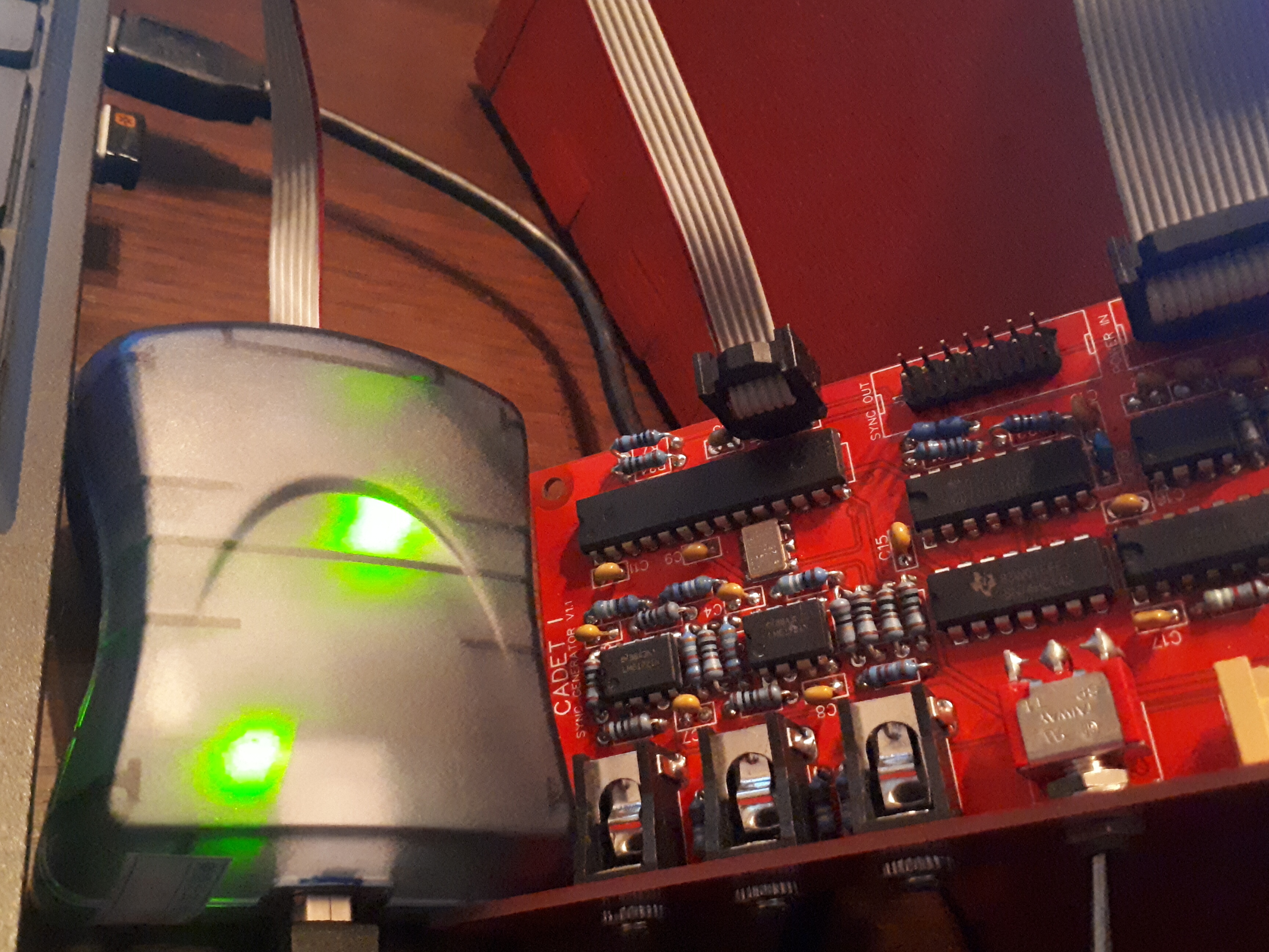
As far as testing the sync output pins, each pin except the bottom 2 is reading roughly 5V. I’m not sure if I’m doing your quick and dirty test properly, I just took a patch cable into a VCA and touched the other end to the sync output pins. Each pin, including the bottom 2, sent out a tone, a bit higher than 60hz, but it’s the same tone I get from touching pretty much anything it seems (for example the RCAs or the 5V leg of the regulator).
Thanks for the tip about LZX reaching out about unprogrammed chips. I sent them an email, though as I followed what seemed good advice and I didn’t use sockets on the cadets, the prospect of desoldering this ATMEGA is about as daunting as trying to program it.

#30 — VisibleSignals · 2020-01-23
You’ll need to make sure the Cadet module and the euro gear you’re using to test both share the same ground otherwise there will be stray hum like you’re describing. Probably the easiest option might be to plug a patch lead into the vertical sync output socket on the front of the Cadet instead.
I would guess LZX may send you a new chip; if they do then it might be best to just cut the existing chip away and carefully desolder each leg from the PCB. Desoldering a chip with that many pins intact is tricky
The GND pin on the programming socket J10 is the one furthest from the ATMEGA, on the outside edge of the board and closest to the J1 sync out connector, diagonally opposite to the J10 pin with the square pad on the PCB. See if you can work out which pin is GND on the programmer cable socket in order to make sure it’s oriented correctly. Use your multimeter to check resistance from a known GND point on the programmer to confirm.
#31 — Whelm · 2020-01-23
The programmer is oriented properly, I found the pinout and it matches the LED indicator.
None of the output jacks produce any audible tone, I should have been clearer on that earlier in the thread, I see what you mean now. And with the VCA sharing gnd with the cadet there is no audible tone off any of the sync out pins. Which, if I understand, is consistent with an unprogrammed ATMEGA.
So to recap, at this point I’ve traced the circuit for continuity as best I can, I’ve checked that all the ICs are getting power, so I’m fairly certain that the ATMEGA is where the problem lies. So then the solution would seem to be to program the chip.
But the programmer returning a device code of 0x000000 suggests that either the chip itself is bricked somehow, or that there is some faulty connection on the board that is interfering with the clock (if I’m understanding @transistorcat). I have verified the connections on the crystal oscillator and there does not seem to be a problem there, and it appears, at least using the rough method of a voltmeter, that the ATMEGA is receiving the clock from the crystal.
LZX is going to send me a new ATMEGA, which is great, though I’m concerned why this chip is proving difficult to program.
The only osciloscope I have the budget for right now is something like a DSO 138 or a DSO 150. I might order something like that while waiting for the chip from LZX, hopefully that’ll be sufficient.
#32 — VisibleSignals · 2020-01-23
I have a DSO138 - very convenient size. It only goes to 200Kc/s so it’s fine for audio and video frame and line rates but won’t show you video waveforms. For what you’re testing now that should be fine.
Glad to hear you’re getting a replacement chip!
#33 — transistorcat · 2020-01-24
AVR programming seems to be a recurring theme here for multiple people so i’ll try to expand a bit on the relevant bits.
ISP programming on the AVR is just a SPI serial protocol with reset as the chip select line.
Reading the ID is usually the first thing done when trying to program the chip. an all-zeroes response here just means the line stays low during the entire operation - i.e. that the MISO line is shorted, disconnected from the target, or that the chip is unresponsive.
What it does indicate is that the programmer sees some voltage between the GND pin and the VCC reference pin that is within the legal levels for the device, as checking the voltage is the only thing done before trying to read the ID.
If we rule out misconnection and soldering-related opens/shorts on the programming lines on the PCB (and re-checking all these might be worthwhile to a level of tediousness ) what remains is that the device simply for some reason does not answer.
This is usually because you have managed to lock yourself out somehow with the fuses (It’s quite hard to electrically completely break an AVR in a way that doesn’t leave marks).
If you’ve been messing with them (doesn’t sound like you have), this could be Brownout detector (But in this case we’re running at 5V, so that can’t be it), debug/programming settings, i.e. turning debugwire on or SPI off (the former is fixable, the latter would require you to desolder the device), or clock related.
The clock one is interesting, because setting the device to an external clock and then not providing one would leave the device looking rather dead. On the cadet, the “worst case” setting is intended (external clock) and the board provides this clock. What that does mean is that we probably can’t easily mess this fuse up in a way that leaves us locked out, but it also means that if something is broken or mis-assembled around the clock generator, these symptoms are expected.
#34 — Whelm · 2020-02-05
Final update: while waiting for an oscilloscope kit and the new chip from LZX, I went over every solder joint again just to be extra super sure. The chip still would not be programmed.
The chip from LZX arrives. Pop out the old one, put in the new one. And everything is finally working.
I have no idea why neither avrdude on Linux nor AVR Studio on Windows would recognize the old chip, but oh well who cares. Hopefully I find some use for this programmer in the future.
Thanks so much to everyone who has been helping me figure this out. The support I get from the SDIY community when I run into problems above my paygrade is a really lovely thing.
On now to testing all the other modules.
#35 — joem · 2020-02-05
Whelm wrote:
Hopefully I find some use for this programmer in the future.
Look into programming AVR chips! It’s a lot of fun. The ATmega328P is the chip the Arduino UNO uses (and is kind of similar to the chip the Cadet sync generator uses too), and once you look into Arduinos you realize that they’re just a few additional things tacked onto an ATmega328P. That’s it. So you can build a stripped down Arduino just by putting an ATmega328P on a breadboard and adding a few resistors, capacitors, LEDs, and buttons and using your programmer to program it (instead of the UNO’s built in USB). The Arduino software will likely support your programmer just fine, so you can use the official Arduino example programs, even.
Doing video stuff on AVRs (especially ones like the ATmega328P) is kind of tricky. Well, doing video stuff on any chip is kind of tricky. But there’s an Arduino TVout library that exists that can make some really blocky (but cool) B&W text and graphics on NTSC (and maybe PAL? I can’t remember), so there’s already a jumping off point there. Also if you’re doing a breadboard Arduino, you can use a different timing crystal to get something better suited to your intended composite format, and then you can take the video output even further and do color graphics at higher resolutions. (I keep meaning to fiddle with that myself, but my Arduinos and ATmegas are still buried somewhere in my room from my move a few months ago.)
Plenty of non-video stuff to do with Arduinos/ATmegas, too… Too many to list here. One thing they’re pretty great for is designing cool standalone gear to generates MIDI signals of some sort… sequencers, keyboards, etc.
Some people are fine with jumping into AVR C, while others prefer to start off with Arduino’s version and then eventually expand to raw C, so there are a variety of different levels of tutorials/articles about it all. The Arduino ones are especially beginner friendly, usually, so start there if you’re unsure.
Such a big and fun rabbit hole to go down!
#36 — VisibleSignals · 2020-02-05
Welcome to the exclusive DIY video synth gang @Whelm!