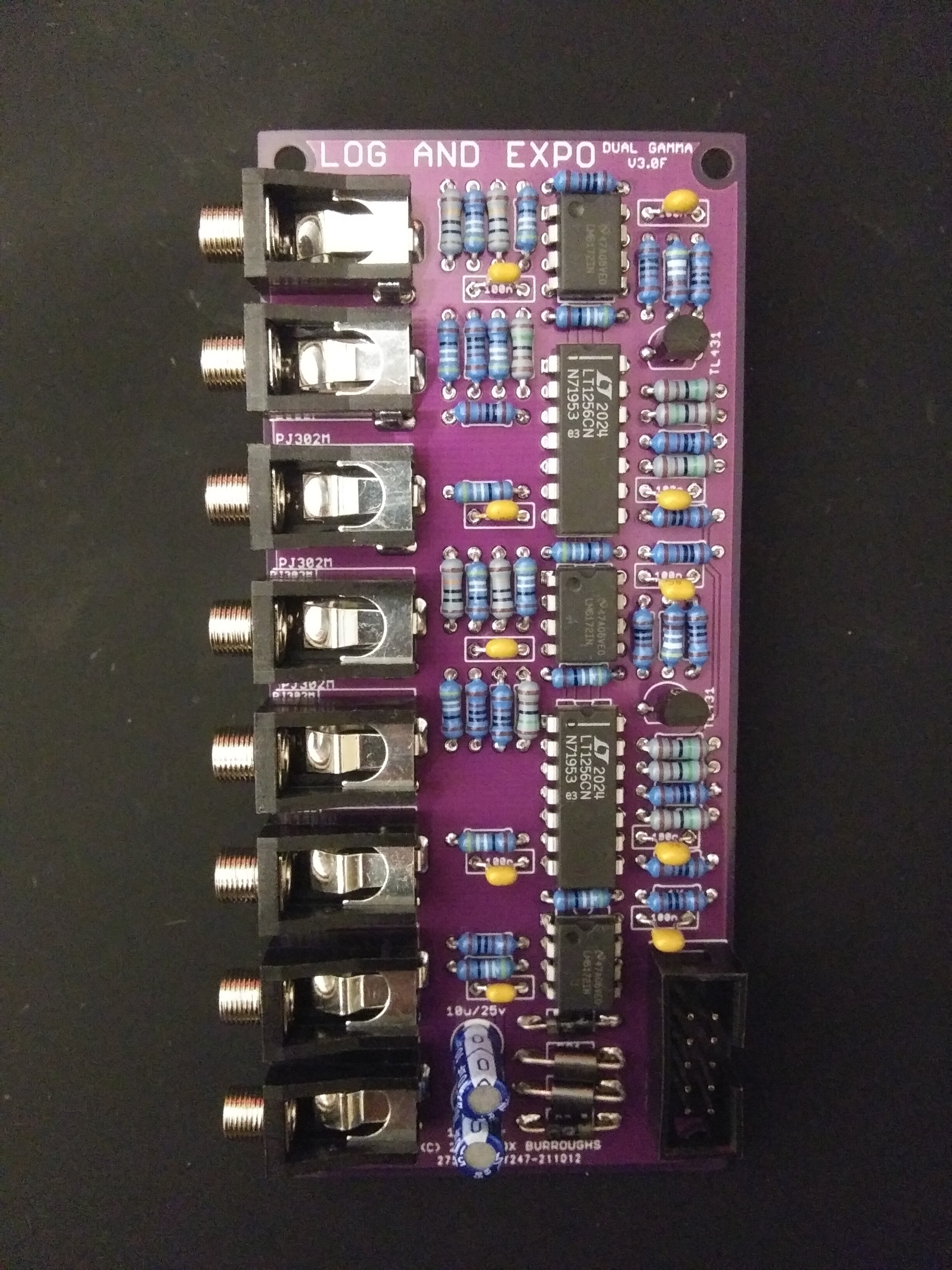
[ORDER] GAMMA - Dual Squaring and Logarithm
Category: Unknown · Tags: — · Posts: 30
#1 — Fox · 2022-03-20
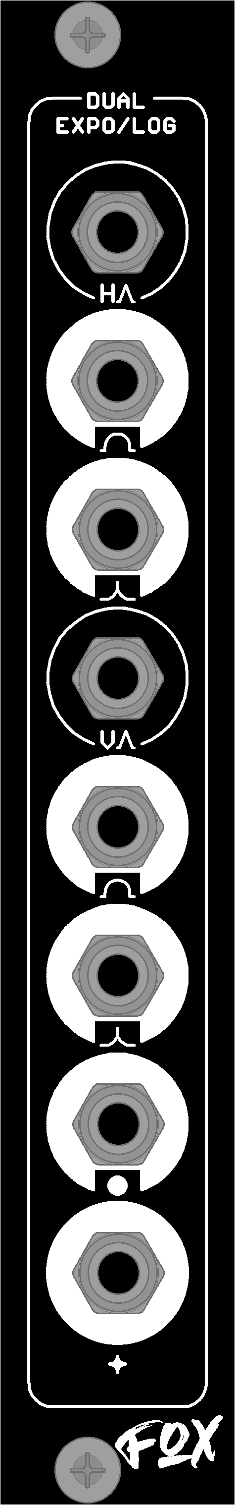
Description:GAMMA features dual squaring and logarithm functions to adjust the light/dark distribution of provided luma signals. Also featured are two summed outputs which mix both of the above square and log results to easily create circles and four-point stars given a Horizontal- and Vertical-triangle ramp.
Square and Log functions may be used to shape the curves of Control Voltages, adjust the gamma of luma signals and process ramps into soft-edged shapes. Each gamma shaping sub-circuits is functionally identical but patching both a horizontal and vertical triangle ramp or oscillator will result in circles and four-point stars at the bottom two outputs. Patch the Circle and Star outputs into keyers for hard edges or into faders to modulate between the shapes.
- 4 HP
- 50 mm deep
- 32 mA +12V
- 26 mA -12V
- ModularGrid
Prices:
DIY PCB/PanelBuiltGAMMA $26$159 See Other Available Modules**LUMA MULTA MULTB SHUTTER VEIL NVRT DAISY ACCESS ABC dual RECTIFIER PASS4 - Quad Passive Switch SW6 - Expander **
- DIY PCB/panel orders include circuit boards and faceplate only, users must source components listed in the BOM below.
- Built modules are personally assembled, cleaned and tested. Each include a 6" 10-16 pin power ribbon cable.
- Please respond below or DM me to place an order.
#2 — Fox · 2022-03-20
Video Example courtesy of Rempesm:
https://www.youtube.com/watch?v=i-X62FnF7J0More examples planned.
#3 — Fox · 2022-03-20
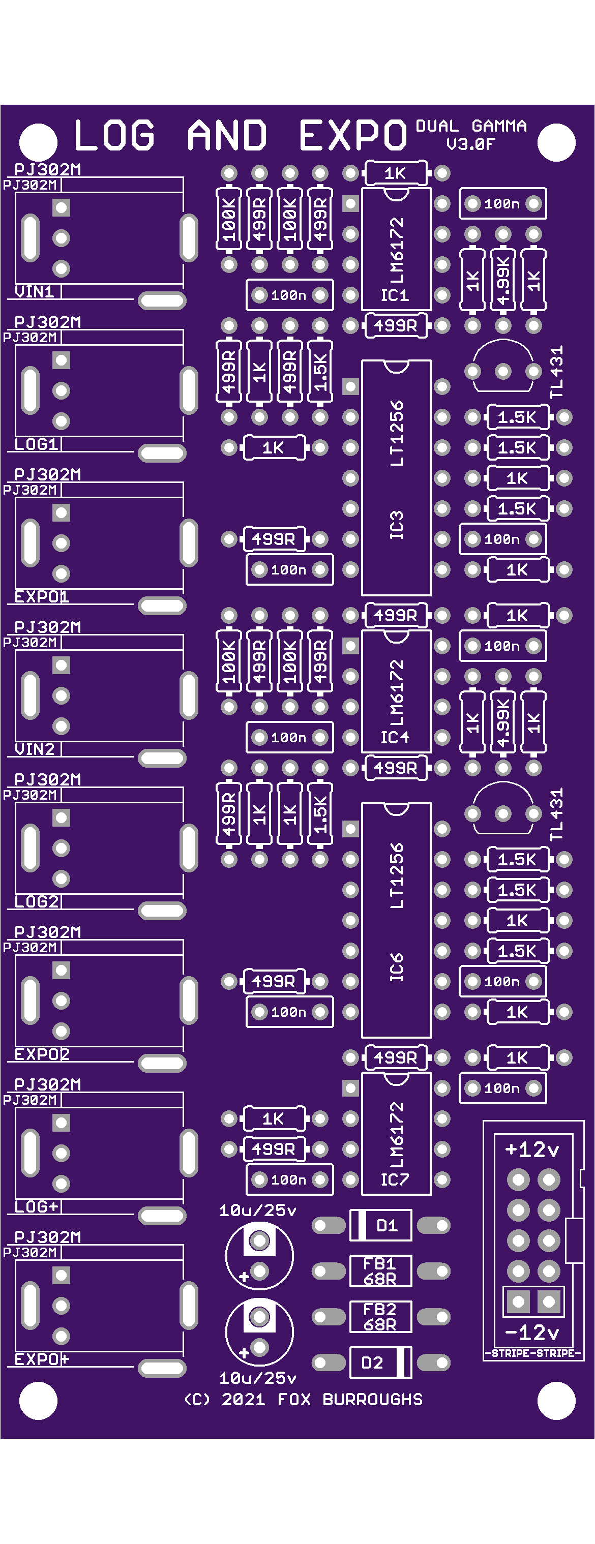
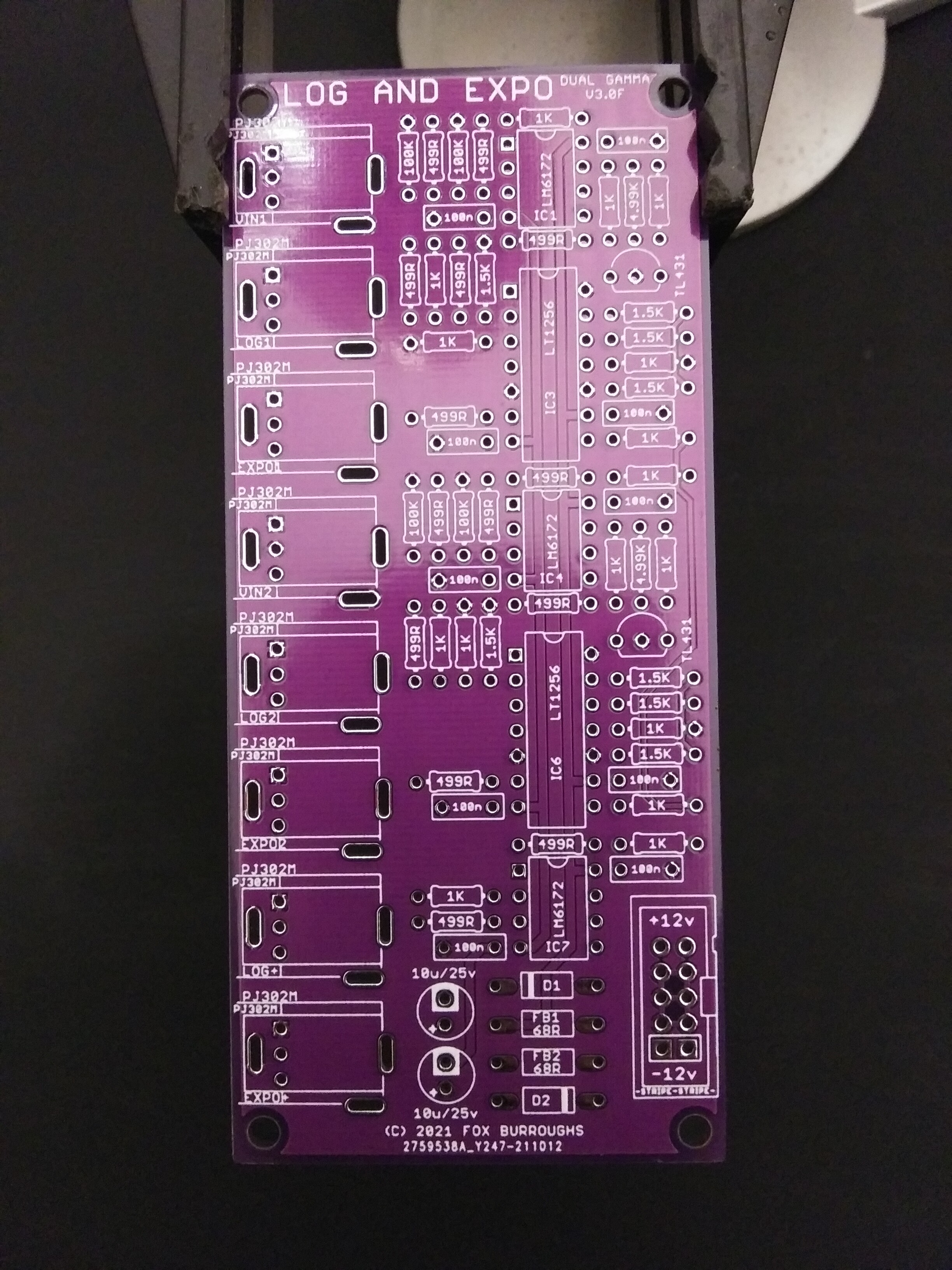
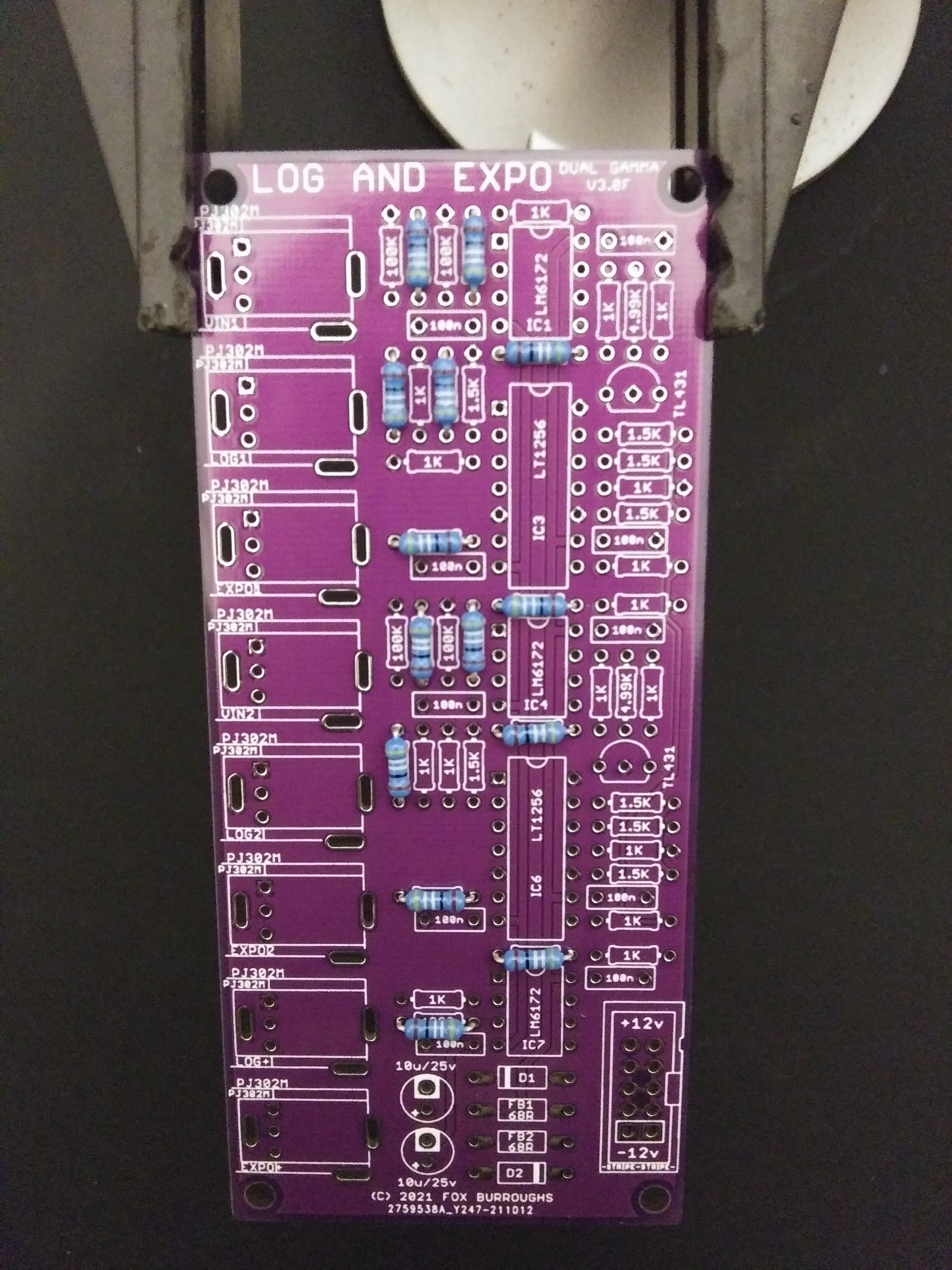
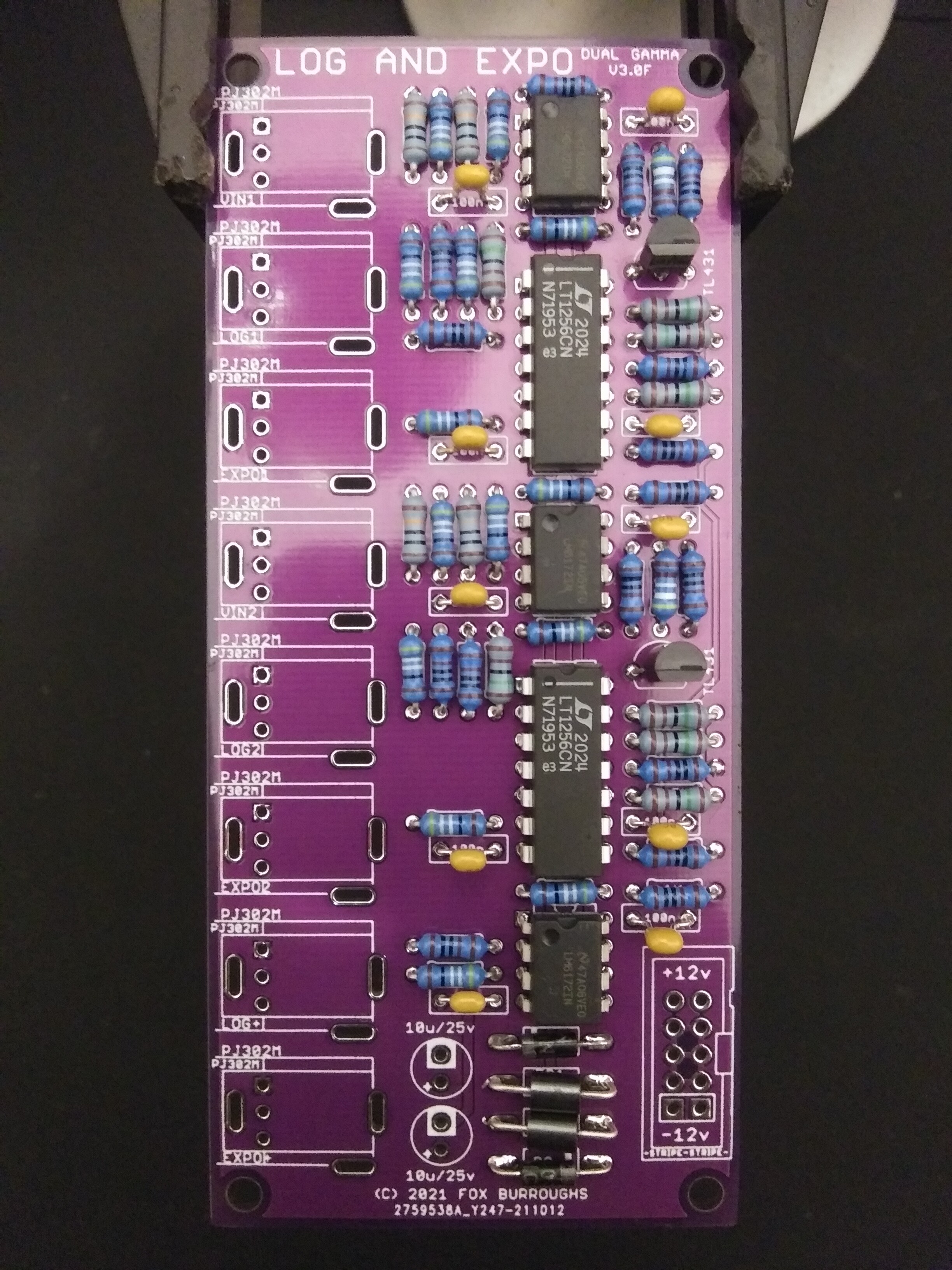
Click for BOMQtyValueParts14499R resistorR2, R5, R11, R13, R17, R18, R20, R23, R29, R31, R35, R36, R43, R44161K resistorR10, R12, R14, R15, R16, R28, R30, R32, R33, R34, R37, R38, R39, R40, R41, R4281.5K resistorR6, R7, R8, R9, R24, R25, R26, R2724.99K resistorR4, R224100K resistorR1, R3, R19, R21268R ferrite beadFB1, FB221N4001 diodeD1, D210100nF capacitorC5, C6, C7, C8, C9, C10, C11, C12, C13, C14210uF/25V capacitorC3, C43LM6172IC1, IC4, IC72LT1256IC3, IC62TL431IC2, IC5110-Pin IDC Box HeaderCONN98PJ302M jackEXPO+, EXPO1, EXPO2, LOG+, LOG1, LOG2, VIN1, VIN2NOTE: Order part LT1256 and not LT1251.
Click for Build GuideStep 0.
I recommend using a PCB vice to hold your board while working on it.
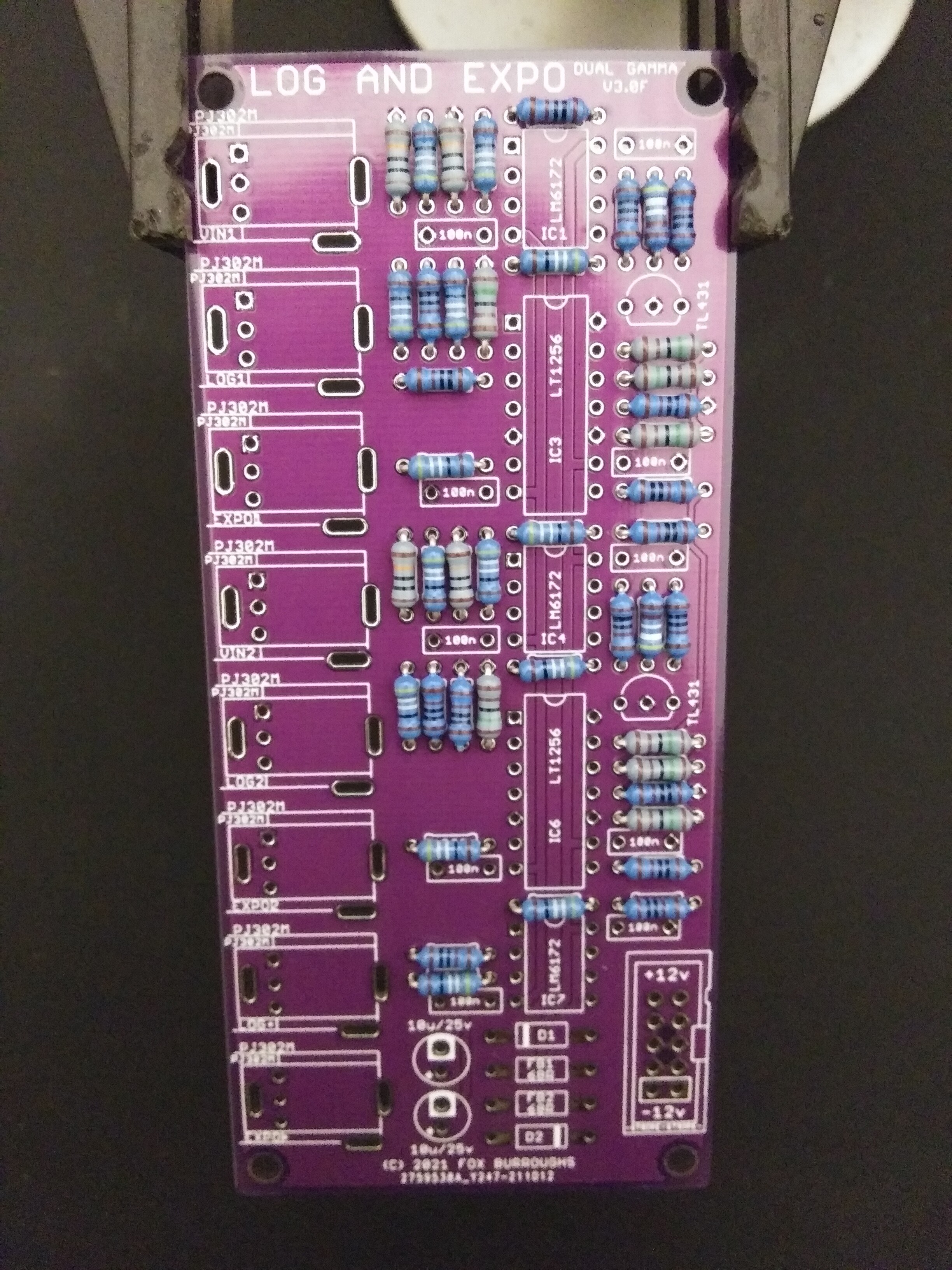
Step 1.
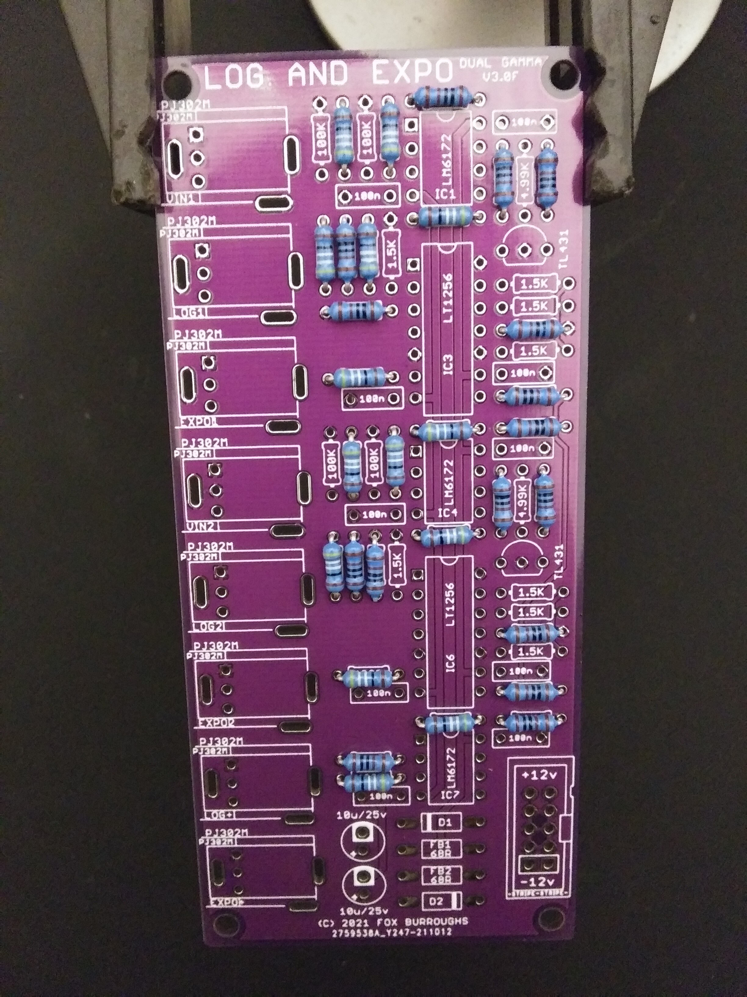
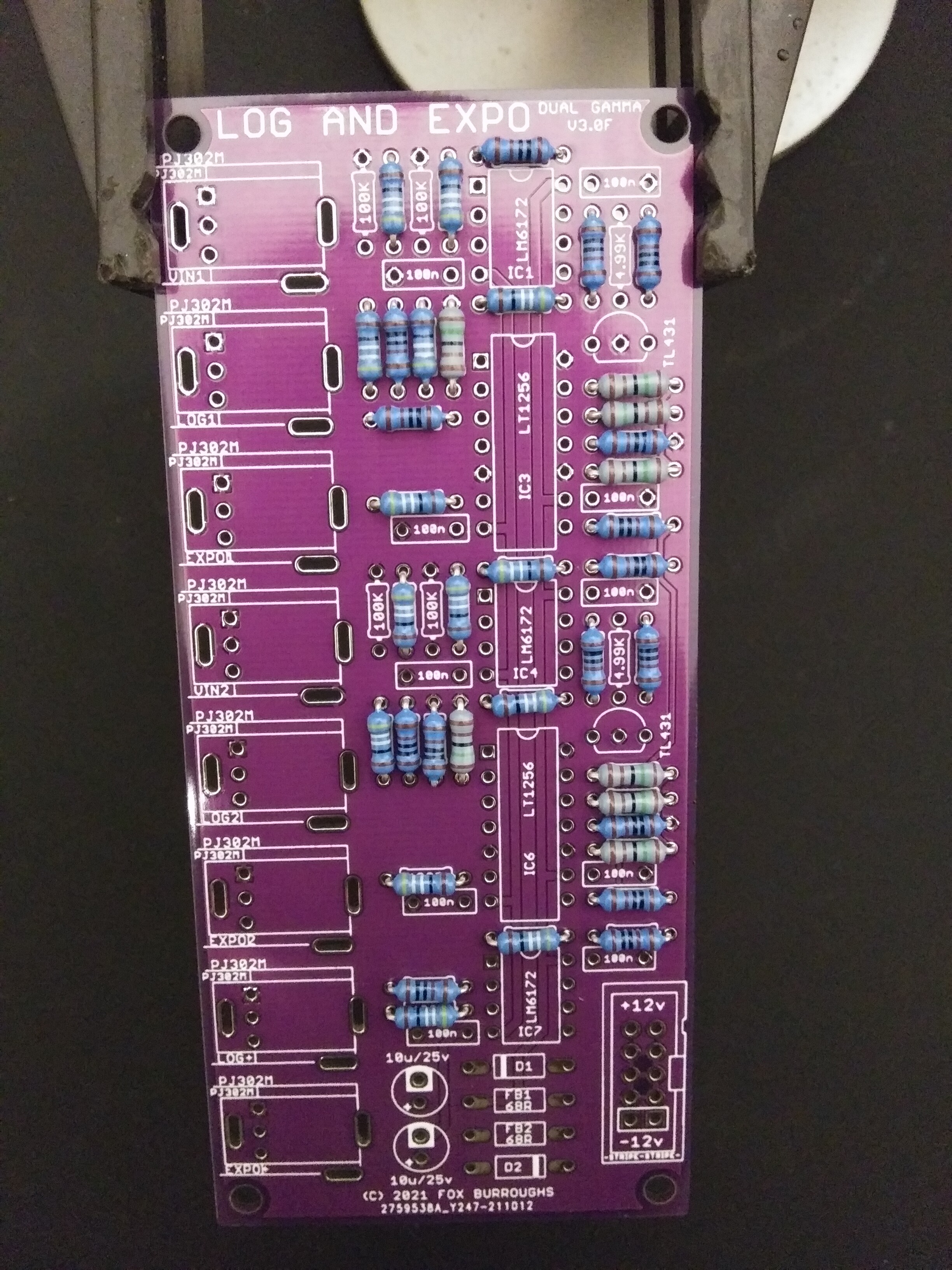
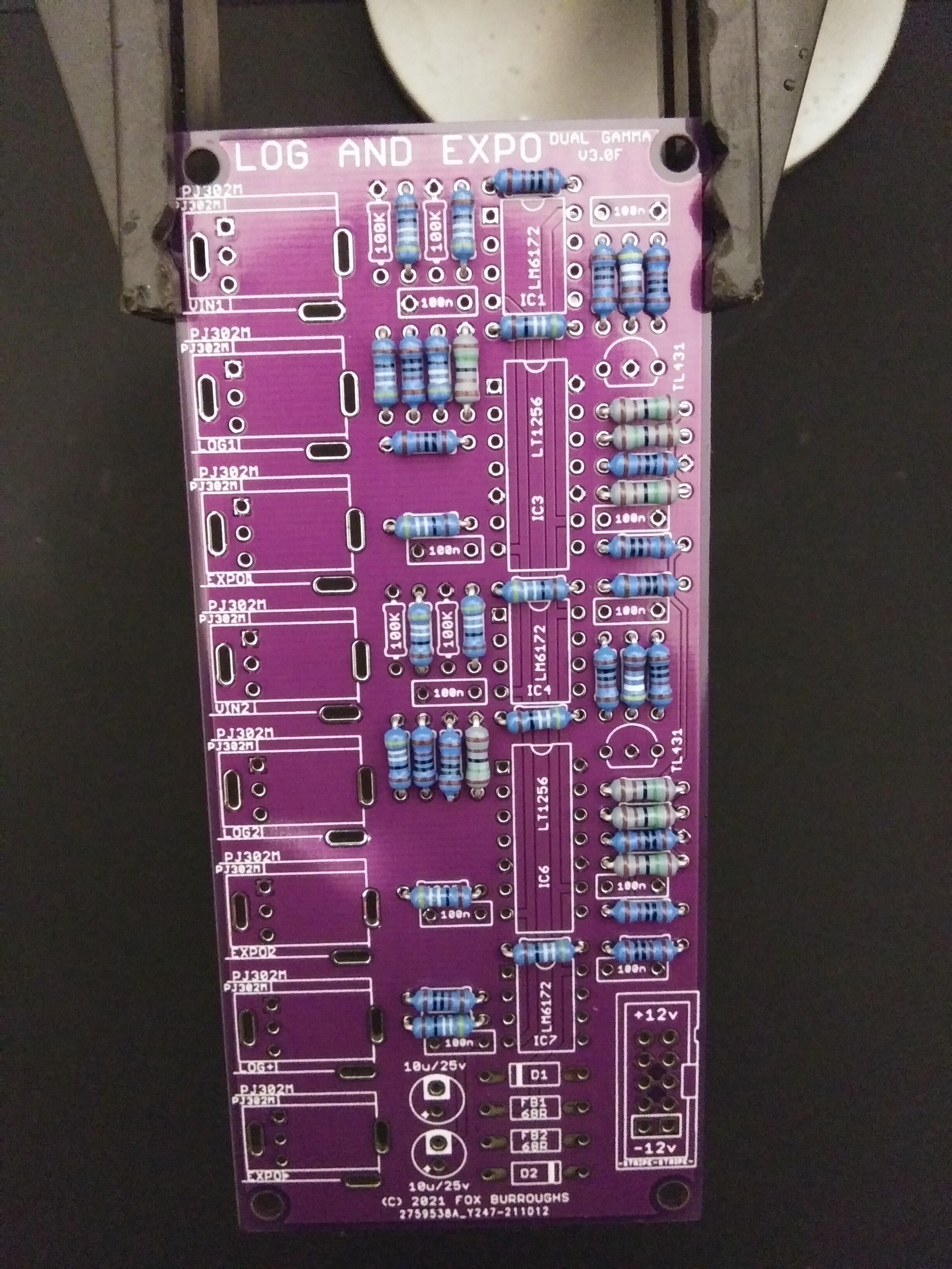
We will start with the shortest components and move up. First, populate all fourteen of the 499R resistors.
Step 2.
Now populate all sixteen of the 1k resistors.
Step 3.
Populate all eight of the 1.5K resistors.
Step 4.
Populate both 4.99K resistors.
Step 5.
Populate all four of the 100K resistors.
Carefully flip your board over; solder and clip each lead.
Step 6.
Now populate both diodes and both ferrite beads. Make sure that you line up the stripe n each diode with the stripe on the PCB.
Solder and clip leads.
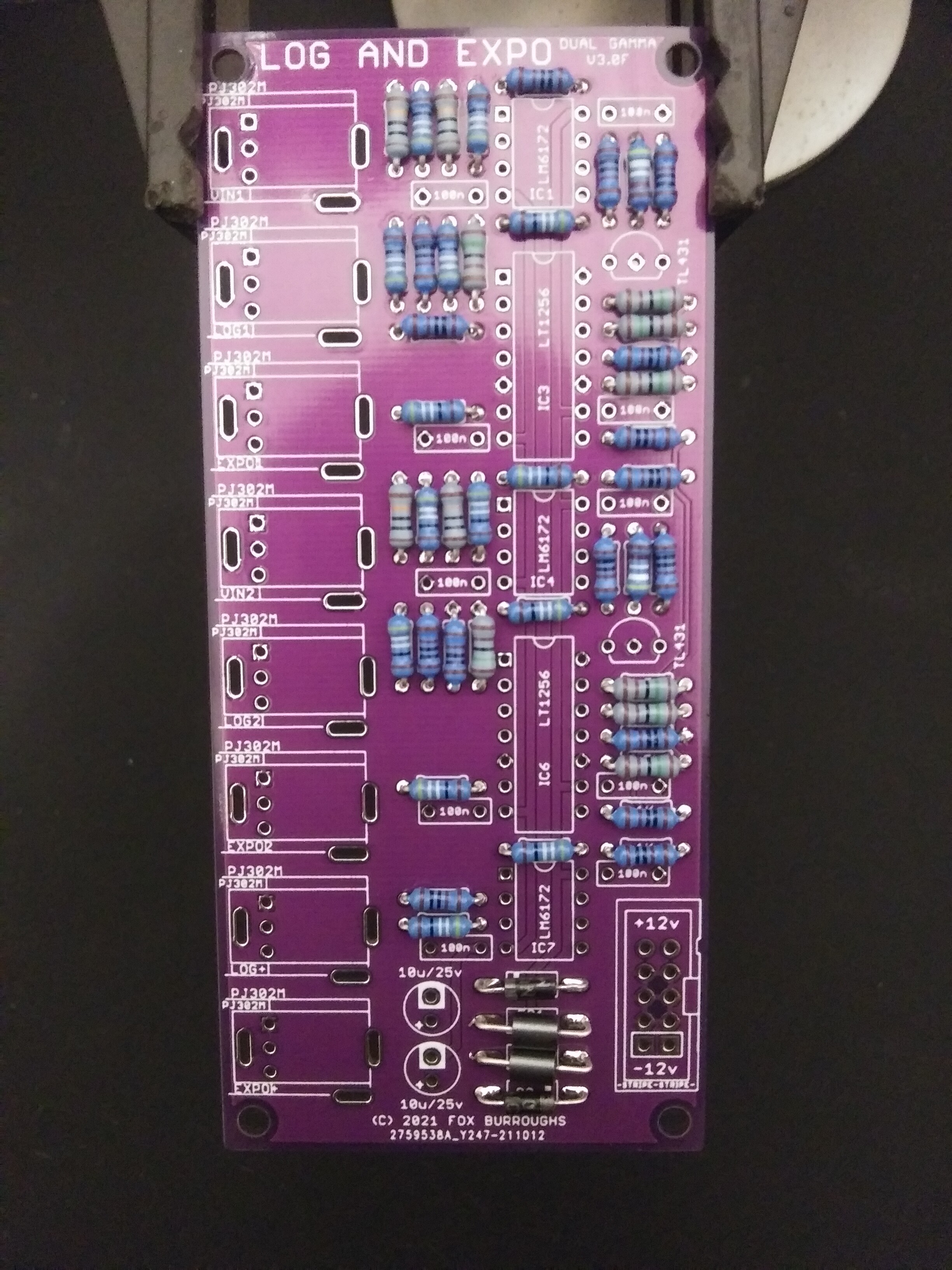
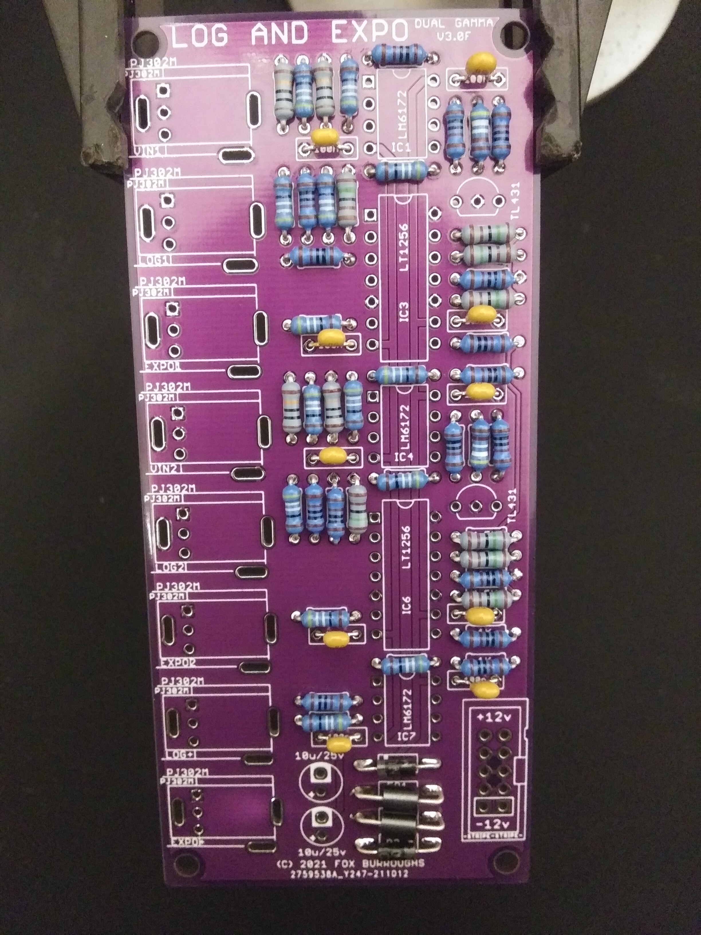
Step 7.
Populate all ten of the 100nF (104) ceramic capacitors. Solder and clip leads.
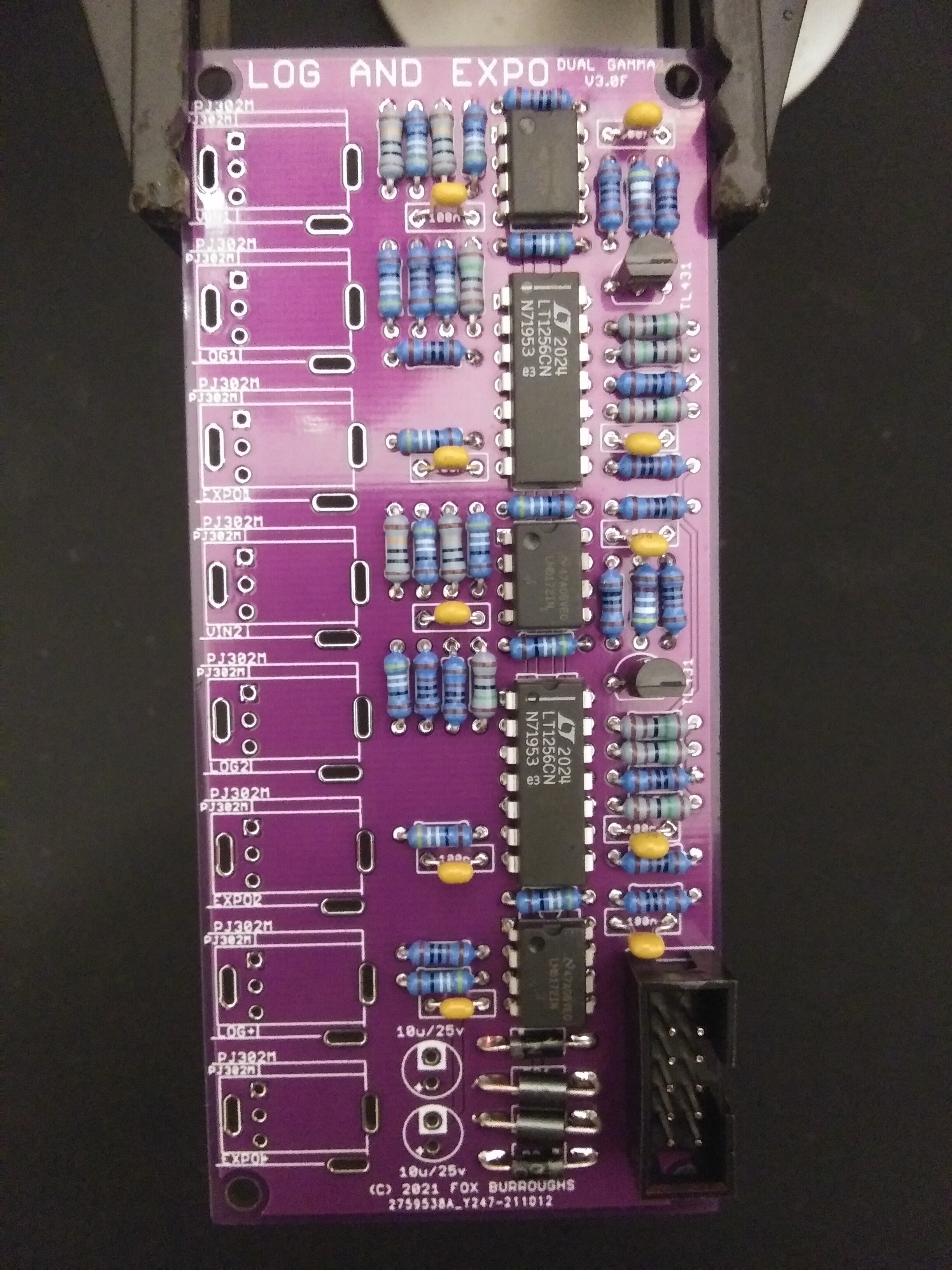
Step 8.
No we can populate the IC’s. There are three LM6172’s and two LT1256’s, each with a notch or line indicating pin 1. This pin must be position in the top left via. Solder legs in place.
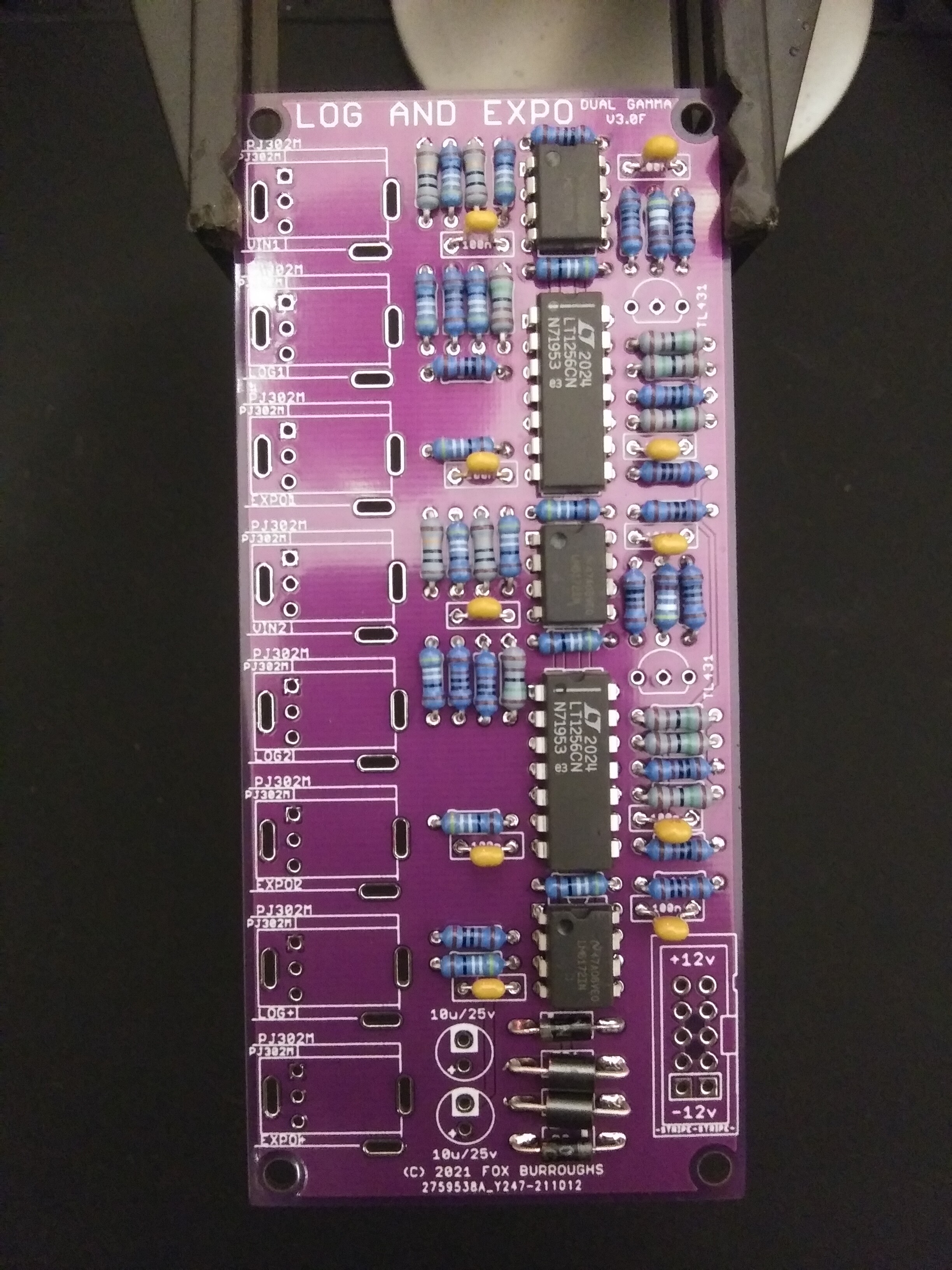
Step 9.
Now populate both TL431 voltage references. Rather uncommon, this board features two to save space and cost on a separate buffering op amp.
Step 10.
populate the 10-pin power connector and line up the notch on the part with the indicator on the PCB. Solder it in place.
Step 11.
Now populate both 10uF electrolytic caps. Make sure the stripe on your caps lines up with the (-) pin on the PCB.
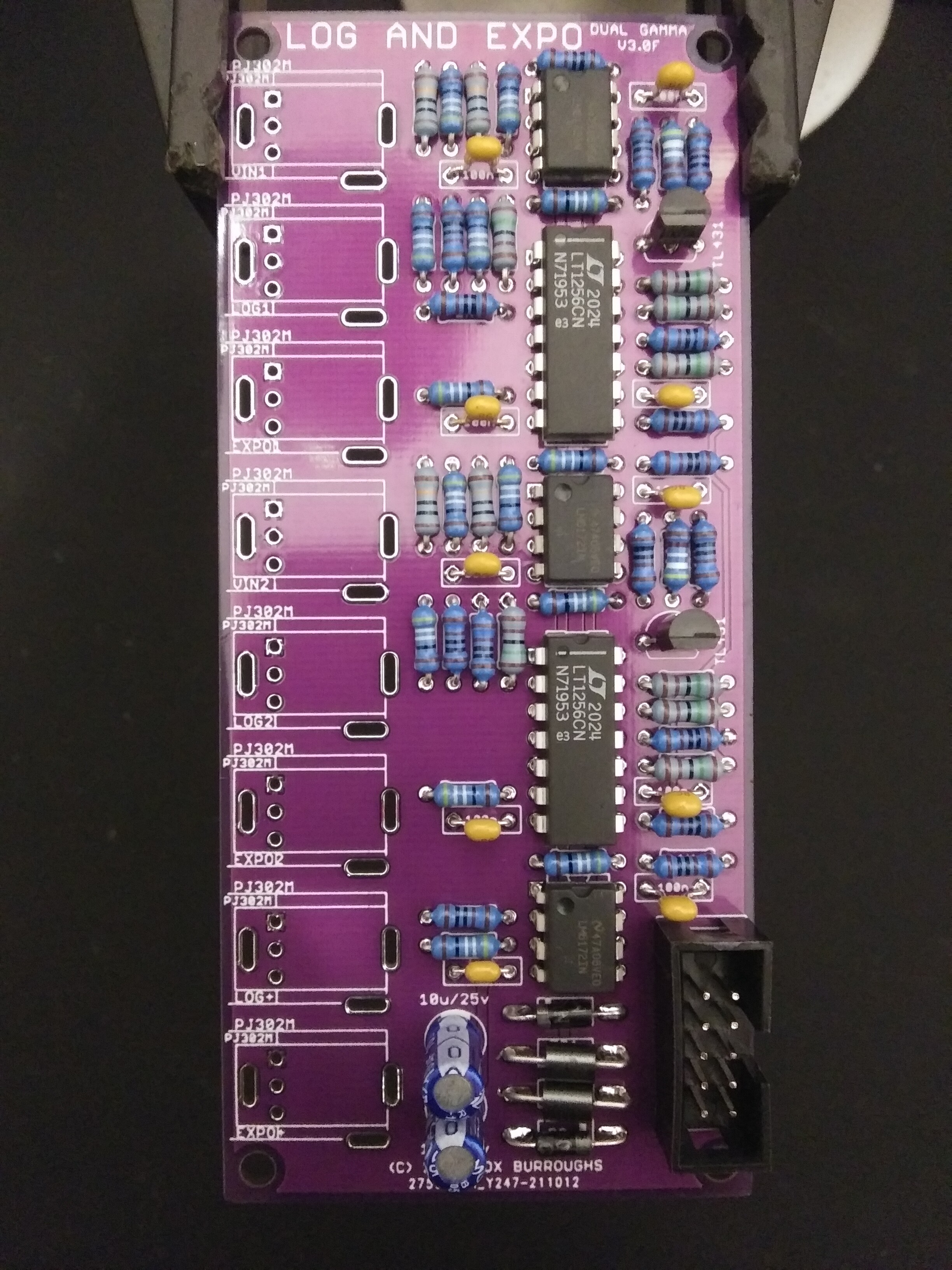
Step 12.
Finally, place each jack in place and carefully install the faceplate. Finger tighten a nut on each jack to make sure they are straight before soldering them in place. Once youre satisfied, flip the board over and solder each leg.
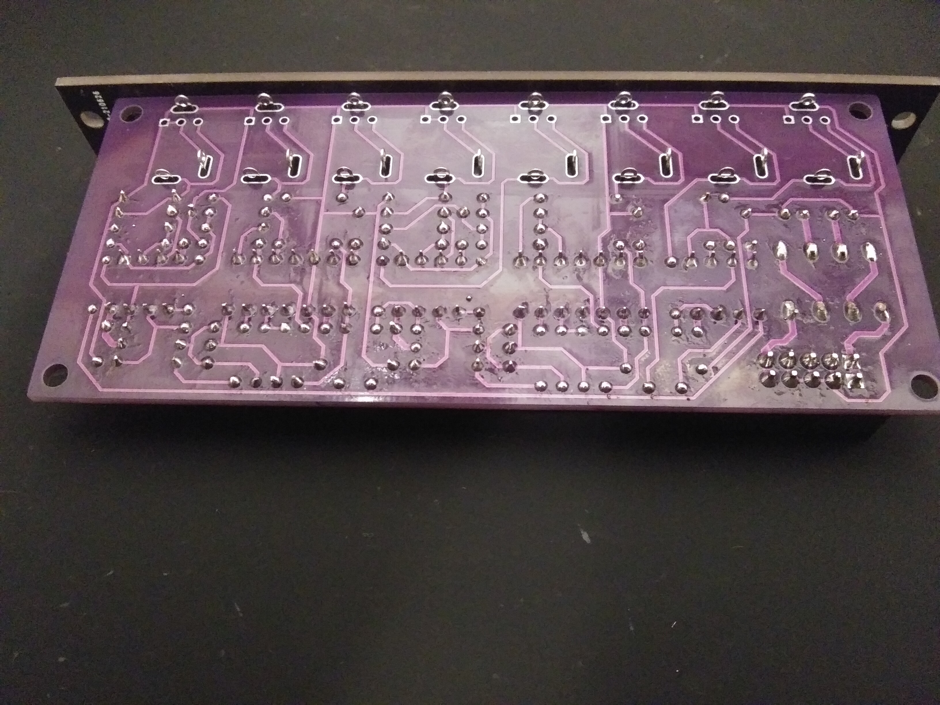
Step 13.
I recommend cleaning your board with a toothbrush and isopropyl alcohol before testing. Take a very careful look at each of your solder joints for any shorts or cold joints.
You may finally test out your work.
Printer Friendly BOM & Guide here.
#4 — Rik_bS · 2022-03-21
I’ll put myself down for 2x PCB + Panels, to be shipped to Australia
if others down this way want to order and consolidate shipping, I’ll be willing to help out
#5 — Fox · 2022-03-21
Thats sounds like a great idea. Tag anyone you think might be interested. You could also ask aroudn FB and Discord if you think it could help out.
#6 — transistorcat · 2022-03-21
I’d love two pcb sets
#7 — hewed · 2022-03-22
I’ll take one PCB and panel to include in the @Rik_bS Australian order, please. Also pcb and panels for a dual rectifier and switches if available, thanks.
#8 — Fox · 2022-03-22
transistorcat wrote:
I’d love two pcb sets
I’ll message you soon!
hewed wrote:
I’ll take one PCB and panel to include in the > @Rik_bS> Australian order, please. Also pcb and panels for a dual rectifier and switches if available, thanks.
Great! Which “Switches” are you referring to? The “PASS4 - Passive Switch” or the “SW6 - switch expander?”
#9 — hewed · 2022-03-22
Sorry, an SW6 please
#10 — phosphenes · 2022-03-22
Anyone in the UK interested in a combined order?

#11 — allthesixes666 · 2022-03-22
hi! Yep - can do a UK combi order again
Please put me down for 3 x diy/pcb/panel and lets see if there’s any more UK interest.
#12 — phosphenes · 2022-03-22
1 diy/pcb/panel for me!
#13 — Fox · 2022-03-22
Running totals per country: Australia:
- 3x GAMMA (rik-2, hewed-1)
- 1x Rectifier (hewed-1)
- 1x SW6 (hewed-1)
UK:
- 4x GAMMA (sixes-3, phosphenes-1)
#14 — VanTa · 2022-03-22
Anyone in Berlin and/or germany for a combined order? Maybe @Robbertunist ?
#15 — hewed · 2022-03-23
If I was to double up on a module, which would be better to do that with - GAMMA or Rectifier?
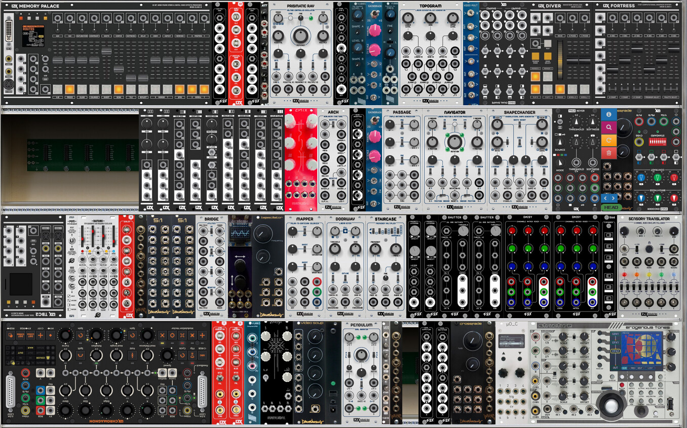
EDIT: For context, image attached of my current rack (including things on the DIY build pile), with back orders upside down.
#16 — jwsmithwick1 · 2022-03-23
Maybe double up on GAMMA so that you have one connected to your cadet ramps, and the other connected to your diver ramps. There are rectifier circuits in both the shapechanger and navigator, so you have some redundancy there.
#17 — Fox · 2022-03-23
hewed wrote:
If I was to double up on a module, which would be better to do that with - GAMMA or Rectifier?
That’s a tough call! They each have the same number of outputs and each half can be used in series with each other… hmm. Too bad we can’t make 1.5U modules.

jwsmithwick1 wrote:
Maybe double up on GAMMA so that you have one connected to your cadet ramps, and the other connected to your diver ramps. There are rectifier circuits in both the shapechanger and navigator, so you have some redundancy there.
Excellent recommendation! It looks like Shapechanger also has a gamma curve knob though.

#18 — rempesm · 2022-03-23
It really depends on what you’re trying to patch. The Dual Rectifier’s half wave rectified outputs (Top/Bottom) are extremely useful for splitting one 0-1V signal into patchable segments. It basically splits your input signal into two segments, below and above 0.5V but adjusts them back to 0-1V range on the outputs. Two Dual Rectifiers gives you 4 rectifier stages which means you can easily split one modulation signal into 4 even segments or more with a little attenuation that can be distributed across multiple modules. I blather on about that here where we talk about how to patch animation timelines.
Two Dual Rectifiers also gives you 4 stages of full wave rectification which can give you a very dense solarization effect. If Staircase is your jam and you want to be able to have a more ‘fixed’ patch programmed version of it, this is the way to go. If you want it to be animated somewhat similarly to Staircase, just run your original signal into a VCA before putting it into the first Dual Rectifier. The first Fold output is normalled to the second input so it just takes one patch cable to have 4 stages available on the output.
I think @jwsmithwick1’s suggestion of hooking your Cadet ramps right up to a GAMMA is a good idea if you are primarily working with shape generation. You’d want to use the inverted triangle ramps if you are after circle/pincushion shapes on the bottom two outputs. It might be a little redundant plugging it into Diver since you already have expo/log ramp waveforms available as two separate banks. Putting an exponential signal into an expo converter just makes the curve that much more dramatic so it’s still useful for experimenting with.
The Gamma control on Shapechanger is effectively the two bottom outputs of the Gamma module routed into a fader so you can go Log<->Lin<->Expo or Circle<->Diamond<->Pincushion Star.
In the context of your system, I’d personally add a 3rd VEIL so you can stack 3 RGB layers. LUMA/RGB2YRGB would also be a handy one so you can pull a key source related to any arbitrary RGB pattern in your system, not just from Memory Palace, TBC2 or Chromagnon. I often take that the Y from that module, key it, and then put it into the CV input of BSO Crossfade to get deep blacks around RGB patterns that exactly matches their shape. Your RGB pattern would first go into LUMA → one side of BSO Crossfade so it requires minimal multing to patch.
That rack seems like a ton of fun already!
#19 — allthesixes666 · 2022-03-23
Thanks @Fox, I am checking with someone else if they want some other bits from you, so if we can see if anyone else chips in here, too - I will confirm via pm in a few days
#20 — hewed · 2022-03-23
Thanks @jwsmithwick1, @Fox and @rempesm.
@Fox - Based on the advice, I’ll add another GAMMA, another Dual Rectifier and a Luma to my order, please.
#21 — hewed · 2022-04-02
@Rik_bS - In the absence of other Australian orders, shall we lock in our joint order and delivery?
#22 — Analogmonster · 2022-04-04
Hi Fox, another UK order to be added here please. Happy to be part of the group order.
1xGAMMA, 1x LUMA, 1xNVRT, 1xACCESS and 1xDual Rectifier, all PCB/panel only
#23 — Fox · 2022-04-04
Running total for UK. Correct me if I am wrong.
EDIT: Updated final totals.
- 3x GAMMA
- 2x Dual RECTIFIER
- 1x LUMA
- 1x GAMMA
- 1x GAMMA
- 1x LUMA
- 1x NVRT
- 1x ACCESS
- 1x Dual Rectifier
#24 — allthesixes666 · 2022-04-05
Hi, sorry for the delay in replying, I’ve had word from my friend, so in total for me:
3 x Gamma
2 x Dual Rectifier
1 x LUMA - RGB
Thanks
#25 — Analogmonster · 2022-04-07
My part of the UK order is correct, thanks
#26 — phosphenes · 2022-04-08
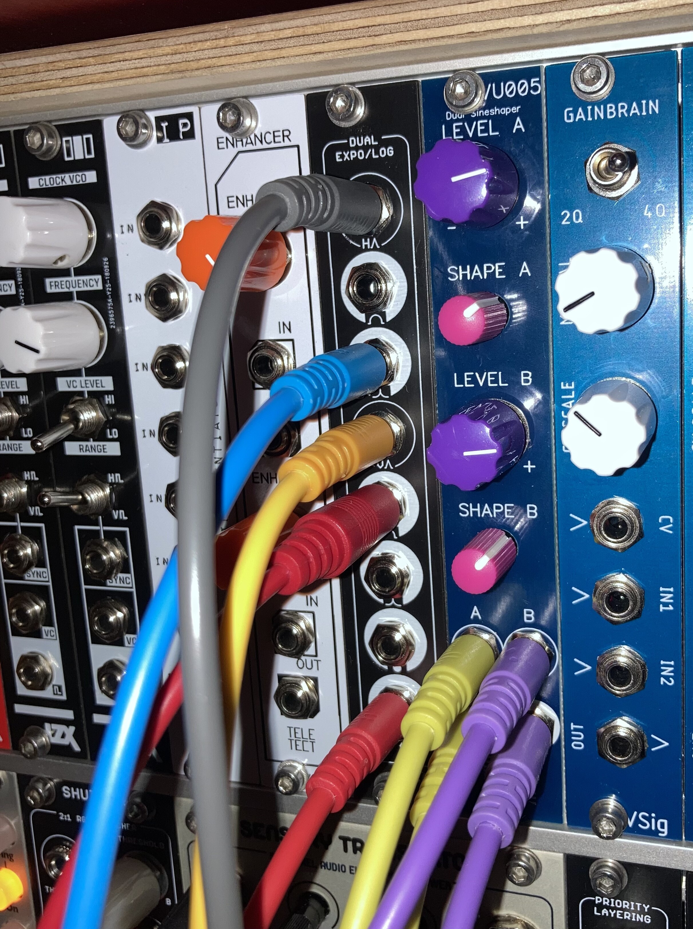
Are the input jacks configured in way that I could run a normalised connection from my cadet Ramps H and V ramps? Would be super useful!
#27 — Fox · 2022-04-08
The inputs are normalled to ground, but I can walk you through which pins to connect to your cadet behind the scenes.
#28 — phosphenes · 2022-05-04
All built up and working like a charm, initially thought the labelling on the circle function had been flipped but of course cadet ramps go \ / rather than / \ !
It’s great having easy access to functions in a DIY rig that used to only be available on built modules.
#29 — rempesm · 2022-05-05
Nice set of DIY modules in your case!
phosphenes wrote:
cadet ramps go \ / rather than / \ !
Yeah, if you’re feeding in an inverted triangle ramp from Cadet IV then you would need to invert + offset it to be what the module is ‘expecting’ to give you circle / pincushion star gradients on the bottom two outputs. Using the Fold output on Fox’s Dual Rectifier, you could take your regular H / V ramps into that and you’d have a positive going triangle ramp on the output to feed into Gamma.
Of course you can patch it up with whatever, it’s just two identical log / expo processors with individual outputs that are summed together at the bottom two outputs. Using triangle ramps, top log output gets summed with bottom log output for the circle gradient. Top expo output gets summed with bottom expo output for pincushion gradient.
#30 — phosphenes · 2022-05-05
Thanks, the drought of built modules meant a lot of DIY which has been a lot of fun!
Yeah that’s what I’ve been doing to get the circle. Getting some nice results combining the ramps with a couple of cadet oscillators and feeding them in too. Endless curves!