[Project] Sync Generator modification
Category: Unknown · Tags: cadet · Posts: 30
#1 — reverselandfill · 2022-12-09
@syntonie and I were talking about a modification of the LZX Cadet C1 Sync generator
Because the 6pin XVCO is obsolete, it is hard to start out with a Cadet system right now.
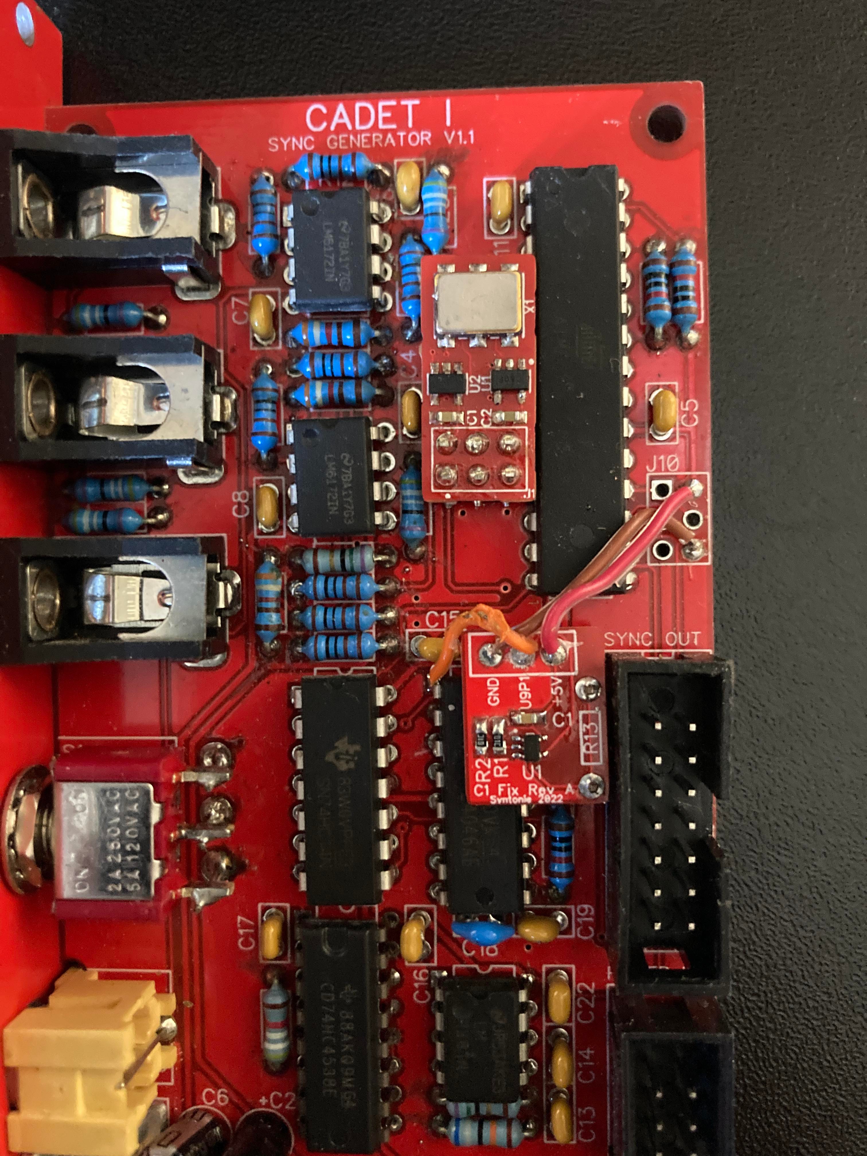
Bastien has designed a XVCO adapter board that uses a 27MHz crystal and a flipflop divider to get the required 13.5MHz
This board could be soldered on an adapted C1 pcb.
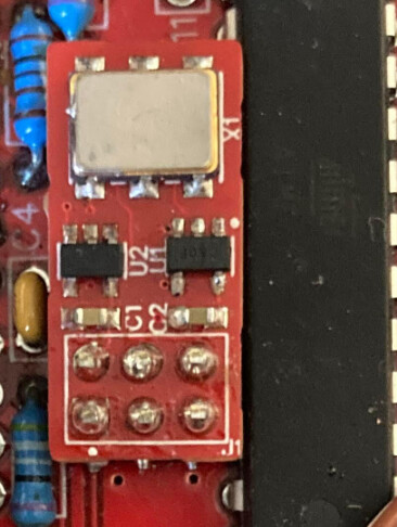
I have recently made a modified layout for the sync generator for an art project, so it would be easy to add this to to board.
We were thinking to add some additional mods:
- RCA sync output on the back
- 1v or 5v signal for the jack outputs via a jumper setting so that it becomes easier to use these with audio modules
- delaying the sync pulse to produce a kind of phase shift
The design will be open source and Gerber files will be posted on Github
Bastien was also thinking that the code could be adjusted to work with the 27MHz directly
but both of us don’t know how to do that. If anyone would like to help with that…it would be great!
If anyone has tips or ideas, please post them!
#2 — dubpixel · 2022-12-09
This is awesome!
Glad someone keeps chipping away at my to-do list even when I’m not hahahahah!
Thanks to both of you for your work.
Edit: found the source.
Found it to be clear and documented.
My “ed” and I have a date in a week or so to Zoom and see if we can put our heads together.
Should be fun!
#3 — reverselandfill · 2022-12-09

github.comhttps://github.com/lzxindustries/lzxcadet/tree/main/C1/Softwaremain/C1/Software
LZX Cadet Series EuroRack Video Synthesizer DIY Modules
Link: lzxcadet/C1/Software at main · lzxindustries/lzxcadet
#4 — creatorlars · 2022-12-10
reverselandfill wrote:
Bastien was also thinking that the code could be adjusted to work with the 27MHz directly>>>> but both of us don’t know how to do that. If anyone would like to help with that…it would be great!
Unfortunately the Atmega IC used has a 20MHz maximum clock frequency, which is a reason we did not use 27MHz in the first place. I have not tested overclocking – could be possible. I’d say the divided VCXO is a better solution if the goal is to maintain the current MCU/code. And if you are going to change the MCU, might be good to change to the iCE40 parts used in the VU007B and ESG3, so that HD sync modes and format detection are possible. I’m happy to discuss open sourcing whatever pieces to that puzzle are needed. But that is probably a different project. Keeping the thru-hole NTSC/PAL sync gen of C1 alive is also a great idea.
There’s another issue you could address with this update –
When free running, the VCXO input voltage should change to 2.5V to set the coasting frequency near the crystal’s median. Right now it falls to 0V, which makes it difficult to use as a genlock reference for other devices, and makes it fall out of range of capture devices like BMD Analog-to-SDI converter.
Easy hack for this is just a switch to select “free” vs “external” modes (4046 filter output vs 2.5V reference voltage going to the VCXO.)
You could possibly even add this on your little adapter chicklet board! I love this because it means existing C1 owners could resolve the coasting frequency issue with a VCXO chicklet update.
Additional note: I haven’t looked into requirements, but if the digital rail can be changed to 3.3V instead of 5V, this does open up the number of supply chain options. 5V VCXOs are more difficult to find these days.
#5 — syntonie · 2022-12-12
reverselandfill wrote:
Bastien has designed a XVCO adapter board that uses a 27MHz crystal and a flipflop divider to get the required 13.5MHz>>>> This board could be soldered on an adapted C1 pcb.
I need to do more tests with the 27MHz VCXO and divide by two flip-flop configuration, though there is a few issues that needs to be look into:
-
the VCXO is specified for 3.3V power supply, it seems to withstand 5V and work as expected, however the nominal frequency still requires 3.3V/2 at the VC pin even with 5V supply. Having the pull-up/pull-down resistor modification as discussed in this thread Cadet RGB Encoder + BMD Mini Analog->SDI = :-( - #10 by syntonie does help with BM Analog to SDI picking up the signal, though it messes up a bit with the genlock. A switch as @rempesm did in the mentioned thread and @creatorlars suggested above would work better, as using the phase pulse out of the PLL as I did isn’t ideal.
-
The addon board is mounted using a 2x3 smd header, so it asks to solder it to the Cadet board in place of the 13.5MHz VCXO and then solder the addon board on top of it, which makes it hard to remove if there is an issue.
I was mostly thinking of a way for DIYers who already ordered some C1 boards to be able to use it with a 27MHz VCXO, however, I’m not sure if there is a real need for this addon board, and going for a redesign of the board as @reverselandfill suggested would make more sense. Here is my C1 with the two addon boards:
I guess there is a few different options as Lars summed up:
-
Keeping the existing MCU and code and replacing the 13.5MHz VCXO with the 27MHz one, adding the divide by two flip flop, and pull-up/pull-down resistors (either manually switched in/out or using an active switch controlled by the PLL as I did). I’ll get back to my modified C1 soon and see if I can tweak the pull-up/pull-down resistors in order to keep the right resting frequency without messing too much with the genlock. Would also ask to use a few SMD parts to keep the board at a reasonable size
-
Replacing the MCU/re-write the code and run it with the 27MHz clock: I guess going from an AVR to an ARM would allow to work with a clock higher than 20MHz, though it would ask to re-write the ASM code accordingly, haven’t worked much with MCU beside a few simple Arduino project, and don’t know about ASM either

Then, I’m might be wrong, but ARM chips only exist in SMD package (?) - Going for an FPGA based sync gen, with iCE40/iCE5, though once again, those only exist in SMD packages, the outer pins of the QFN package the iCE40 comes into can be soldered by hand with a thin iron tip, a good amount of flux and some patience, however the central ground pad will definitely require some hot air and solder paste.
The sync generator board I did for VU007B (LZX Show & Tell, lzxpcb-fpga12 / ESG3 review - #13 by syntonie) could be used, however it is a fairly dense board and even if I soldered the first prototype boards by hand, it is far from being DIY friendly. I could also look into providing the pre-assembled sync generator board, though might be going against the DIY spirit of reducing the assembly cost by doing it yourself.
I think C1 ingenuity is the fact that it is made of through hole components only (except for the VCXO), making it easy to DIY, so not exactly sure what would be the best course of action considering this.
I suppose it would also be possible to source the 13.5MHz VCXO by requesting it from the supplier, but that probably means ordering a 1000 or so, and not sure if there would be enough interest to justify it. Also kind of move away from the open source DIY nature of the project where DIYers can source the components themselves without relying on a third party.
Anyway, open to any suggestions and ready to help keeping C1 alive!
#6 — creatorlars · 2022-12-13
syntonie wrote:
Anyway, open to any suggestions and ready to help keeping C1 alive!
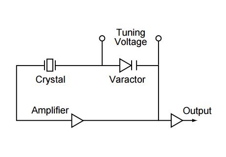
Another possibility is to make a tunable VCXO using a typical 2-pin crystal and a Varactor diode. We used this method in the first Visionary series Video Sync Generator. However it requires a Varactor with a strong pull range and possibly a trim capacitor. SMV1255 is a good Varactor, but pretty expensive.
Another option would be to use something like the HC4046 VCO to generate the MCU clock instead of a crystal. Possibly not as stable, but it could work.
#7 — syntonie · 2022-12-13
creatorlars wrote:
Another possibility is to make a tunable VCXO using a typical 2-pin crystal and a Varactor diode. We used this method in the first Visionary series Video Sync Generator. However it requires a Varactor with a strong pull range and possibly a trim capacitor. SMV1255 is a good Varactor, but pretty expensive.
Ah right, I remember you evocated this solution, so would be something like this?
(found here https://ecsxtal.com/ecs-2520mv/125-electronic-component-technical-guides/125-clock-oscillator-application-notes)And with the trim capacitor in serie with the varactor?
#8 — creatorlars · 2022-12-22
syntonie wrote:
Ah right, I remember you evocated this solution, so would be something like this?
Something like that, but the circuit was simpler. The varactor was in series with one of the crystal’s tuning caps (typically a 20pF to 0V, but in this case the varactor’s capacitor factors in). In the original video sync gen, we tried MV2105 (IIRC) first and then moved to SMV1255. I’ll see if I can dig out that schematic soon.
#9 — Tim · 2023-01-31
@syntonie Is there possibly a gerber or basic schematic you would be willing to share regarding this ingenius adaptor board work around?:)…at the end of the proverbial rope scouring the wastelands of obsolescence haha cheers!
#10 — Tim · 2023-01-31
Hey Lars!

regarding the varactor diode circuit am I correct in assuming the 2 pin crystal would be a 13.5mhz? (sorry for the redundancy with the query just am stuck on the build here and want to be idiot proofing my actions ha!) I have two 13.5mhz crystals currently and am excited to hear of this solution, if that be the case! Cheers!
#11 — creatorlars · 2023-01-31
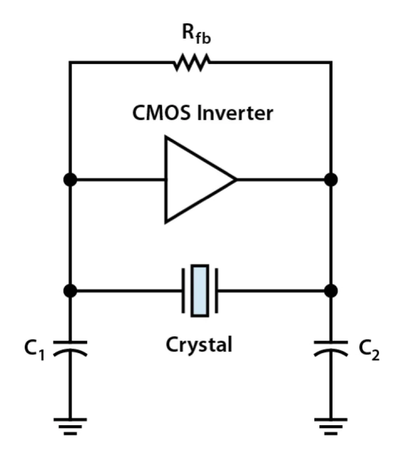
Yes for Cadet1, a 13.5MHz crystal is right. Post the circuit you’re working with if you have trouble with it! The basic idea is to have a typical 13.5MHz crystal oscillator circuit (might need an HC04 buffer), but replace/append the capacitor on one side with the varactor, so that the capacitance can be varied.
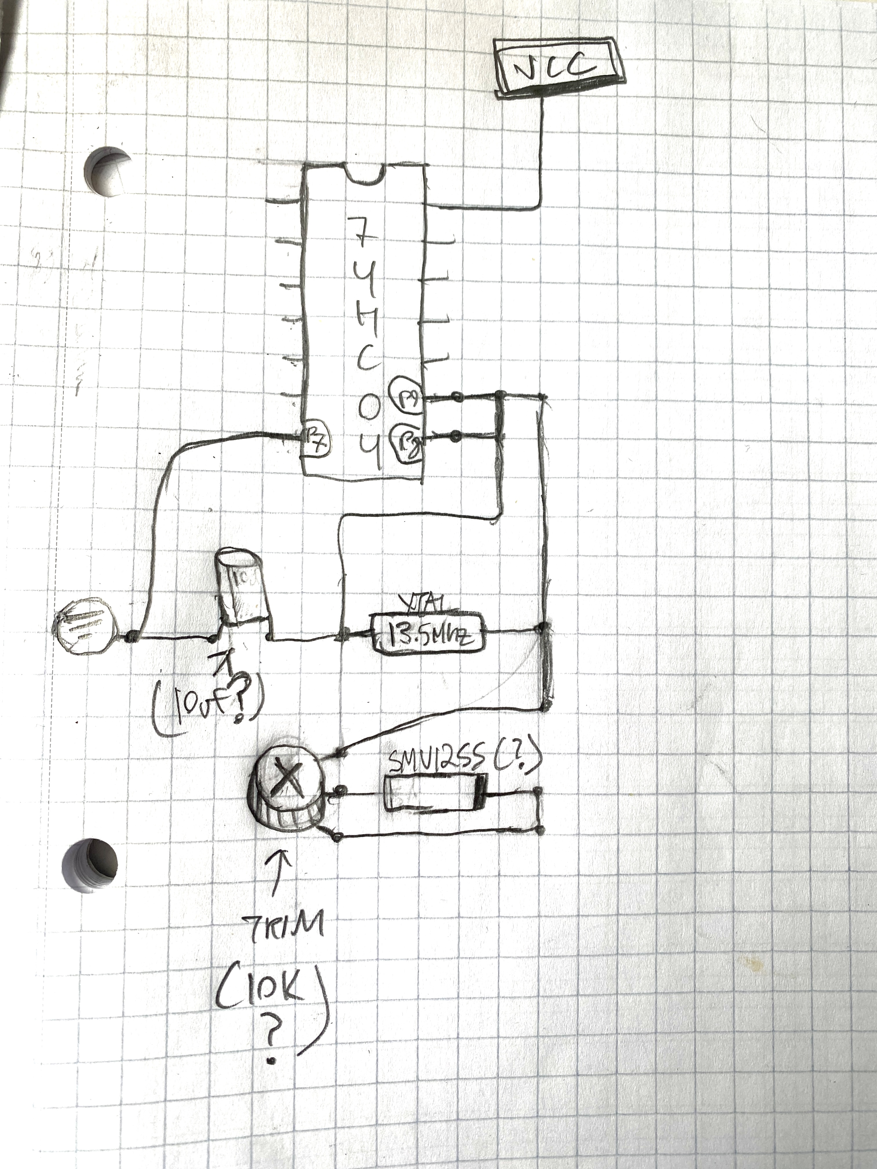
#12 — syntonie · 2023-01-31
Sure, here is the schematic.
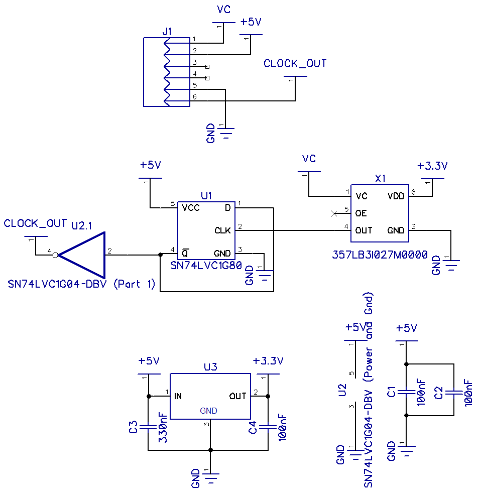
Basically VC, +5V and GND are coming from the connector (J1) that is soldered in place of the existing VCXO.
There is a +3.3V regulator for the 27MHz VCXO (X1) that cannot be powered by +5V (from what I tested, it can, though better safe than sorry

). One issue that I already mentioned above, is that the resting frequency of the VCXO is at Vcc/2 (so 1.65V), whereas the output of the PLL filter will be more about 2.5V (since it is powered by 5V), which is an issue for genlock.The 27MHz output is going into a D-flip flop (U1) wired as a divide by 2, to get 13.5MHz. I’ve added an inverter (U2) at the output of the flip flop, as I couldn’t find a flip-flop with Q output in SOT23 format, only /Q, however I’m not sure if it is really needed.
About the gerbers, I’d prefer to test it a bit more before releasing it. Also, I think now that the varactor solution might be a simpler way to do it, may require some trimming of the VC going to the varactor cathode though but would solve the issue with the 27MHz VCXO needing to be powered by +3.3V.
#13 — Tim · 2023-01-31
Thank you immensely! Also am just reading up on the VU007B …im real close to just splurging on one of the presoldered pcbs

i’m assuming this would help with the ext. sync need for the cadet system(?)
#14 — syntonie · 2023-02-06
Actually, VU007B uses RCA sync, whereas Cadet uses sync over 14pin connector. It can replace Cadet Sync Gen and Cadet Encoder, however for the Ramps and Osc, it would ask for some adapter to go from RCA to 14pin.
#15 — Robbertunist · 2023-02-06
I’ve very recently seen on the LZX Discord that someone was able to connect the Cadet 3 Input module straight to the VU-007B for an external sync via composite. Maybe multing the camera’s output or the C3’s output (hopefully there’s a luma via RCA but surely it’s a jack) means both a VU-007B & a Cadet I, II & III can all lock together to an external genlock sync signal from a camera for instance.
Yes, very optimistic of me to think so & I don’t have the required Cadet modules to try it out but maybe you do @syntonie
#16 — pbalj · 2023-02-06
Cadet III does not convert a composite signal to 14pin sync, but Cadet I will perform that job.
#17 — Tim · 2023-03-05
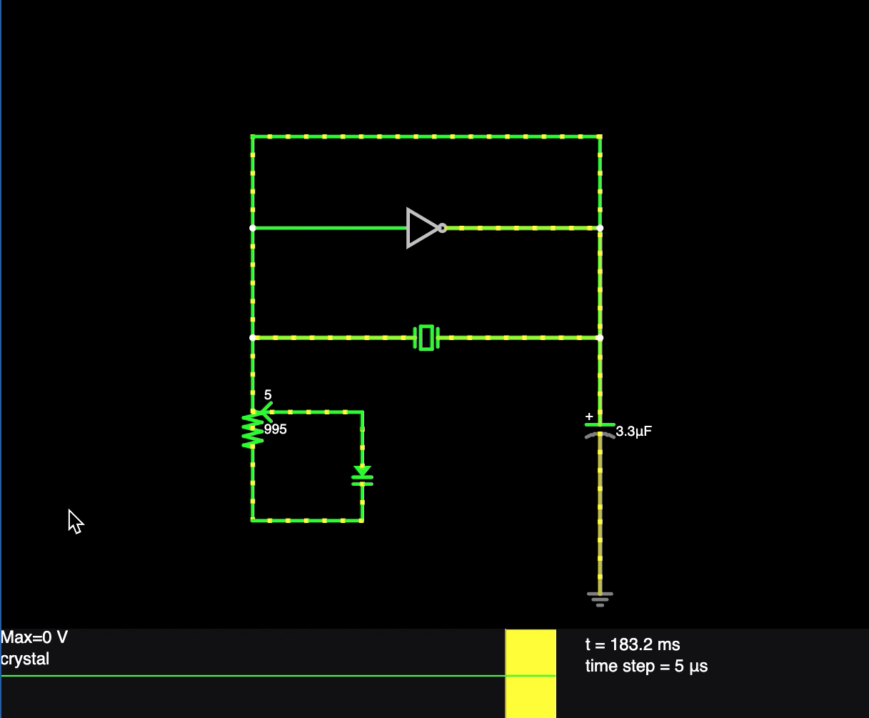
Been messing a bit with falstad trying to figure out the orientation of the varactor circuit. From my swiss cheese brain computations it maybe getting closer? (Also factoring in that I will be sending ground/voltage to the 74hc04)
#18 — Tim · 2023-03-06
Also the values in the above are arbitrary (just working out understanding the circuit).
Heres a notebook jot down…pick it apart and point me in any helpful directions if you could comrades. Cheers!
#19 — Tim · 2023-04-10
Hey y’all so I sourced what is ostensibly the 6 pin 13.5MHZ VCXO. Would anyone have any good ways of going about testing it I should know about? As a noob to much of this… been struggling a bit with verifying its authenticity. Cheers everyone!
#20 — dslocum · 2023-11-30
Hi guys. New here.
Seems this is a critical missing link for the old Cadet stuff. I was going to take a stab at designing this myself, so I’m glad I found this thread.
Assuming it’s working fine - Has anyone updated the PCB to include these mods? I use DipTrace regularly so it should be pretty easy for me if anyone else beside me is interested.
BTW - I see there’s an ELF file but no HEX file for the MPU. I’m not familiar with ELF format. What would I need to burn a chip?
Also, what’s the tool chain I would need to compile the source??
#21 — syntonie · 2023-12-01
dslocum wrote:
Assuming it’s working fine - Has anyone updated the PCB to include these mods?
I haven’t done more tests with the mods, but as stated in my previous post, main issue is the logic being powered by +5V on Cadet Sync Gen and the 27MHz VCXO being +3.3V only. So maybe using a logic level converter to go from +5V at the output of the PLL to +3.3V to feed the lag/lead filter just before the VC input of the VCXO could work, there will surely be a bit of propagation delay, though might be negligible enough.
Else, most logic chips have a Vcc/2 input threshold (here 2.5V) , so in most cases, a +5V powered logic chip can accept a +3.3V signal at its input fine. The only critical part here is the VCXO VC, that needs to be +3.3V, since it expects a linearly changing signal, so it requires to be in the right range for the genlock feature to work as it should.
#22 — dslocum · 2023-12-03
All - I just found this. A little dated, but it has a schematic for a PLL and VCXO that might be useful. And it runs at +5V !!! Are you guys aware?
worldphaco.com
Link: THE_PAL_FREEZE_FRAME_MACHINE.pdf
#23 — dslocum · 2023-12-03
As was mentioned previously, it would be cool if the HC4046 oscillator could be used directly, without the need for a crystal at all. But as someone noted, the stability might be an issue. Anyone tried it yet?
#24 — Analogmonster · 2024-02-27
Is anyone still thinking about taking this further? I have only 1 cadet sync generator but 2 RGB encoders. The plan always had been to have a second sync generator but they sold out before I got around to it
#26 — bathtaker · 2025-07-07
i’m also pinging this to find out if this was ever resolved – i am building a small system, and i would really need two CI’s to get it to work… seems the situation is somewhat hopeless at the moment
edit.; alternatively, are there any modules that could replace 2 Cadet I’s? i would appreciate all input
edit 2: or, perhaps, someone here has the specs of the VCXO in question? i can find some 13.5 mhz ones available… maybe there is some replacement option on the market still?
#27 — joem · 2025-07-08
I don’t have an answer to your questions, but why do you need two C1s (especially for a small system)? Typically you only need one sync generator, and then you distribute that sync from there.
#28 — bathtaker · 2025-07-08
oh, you’re right, i needed to build two because we were thinking of assembling similar systems with a friend. for one system, yes, i intended to use just the one
#29 — joem · 2025-07-09
Cool. Just making sure you weren’t thinking you could use them for something you can’t.

(BTW, if you don’t get an answer here, you can try on the lzx discord. It seems to be more active than this forum these days. Which is too bad because I prefer forums over discords.)
#30 — brettbalogh · 2025-07-28
I just completed a Cadet Sync Generator this past month. It was tricky, but it works well. Here’s some preliminary documentation that might help. It’s still a work in progress. Hope it helps

…Cadet I Sync Generator Documentation
#31 — bathtaker · 2026-01-15
i really appreciate you sharing this! i’ve already purchased and soldered on this Aliexpress 13.5 MHz VCXO that some LZX user found some time ago (and that people have successfully built C1’s with), but i was wondering about this adapter board in the Github as well. very kind of you to document and share your process. i haven’t finished my C1 yet (and need to program the ATMEGA), but if it doesn’t work i might turn to your solution. respect!