Getting Started
What Is A Video Synthesizer?
A video synthesizer is an electronic instrument which creates or processes video images in real time. A modular video synthesizer is comprised of one or more electronic modules. Each module performs a specific function, such as shape generation or color mixing. Modules are connected to each other with patch cables in an open ended manner which encourages experimentation and offers a wholly immersive creative experience. A large system of modules may be purchased at once, or it may be built up over time, according to an artist’s specific creative goals.
Quick Facts About LZX
- The LZX mission is to preserve and expand upon tools available to the video art movement from the 1960s thru the 1980s. LZX exists as a counterpoint to the worlds of mainstream broadcast equipment and GPU based video processing software.
- LZX started as a DIY project in 2008, and then evolved through several series of modular instrument designs. Previous generations of LZX modules were referred to as the Visionary series (2011), Expedition series (2015), and Orion series (2018). The current modular series (2022) is referred to as just LZX Modular, or Gen3.
- LZX products are manufactured in Portland, Oregon at the LZX workshop.
- Modules are compatible with EuroRack cases and patch cables used by modular audio synthesizers.
- Modules can be powered by 12V DC "wall wart" adapters or by EuroRack power supplies.
- External video inputs and outputs are the same as the Component & Composite connections found on most televisions and some cameras.
- Patchable signal levels are in the 0 to 1V range; This is lower than most audio modules (0V-10V), but inputs are tolerant of any voltage produced by a EuroRack system.
- Voltage control inputs are capable of very high frequencies, allowing signals such as camera images to modulate oscillators or VCAs.

Installing Modules
Installing a new module in your system should be done in the following steps. Always power down your system while installing a new module.
Connecting Power
Your power supply must be connected to either the 12V DC input jack or the EuroRack power connector. Do not use both connectors at the same time.
Connecting Video Sync
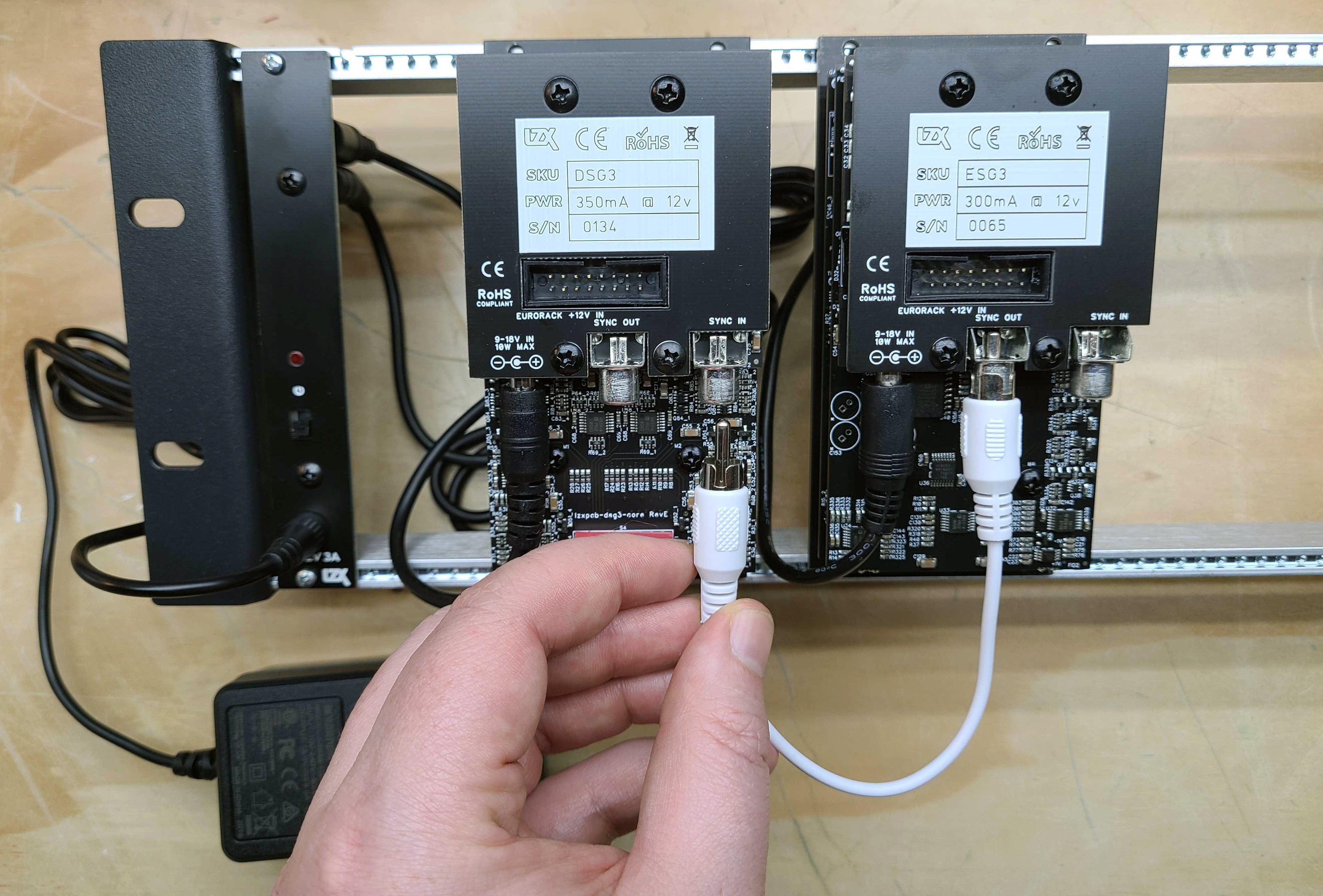
For each module with a Video Sync In on the rear, it must be connected to your ESG3 Encoder & Sync Generator module using an RCA cable. This connection may be made directly, or through a chain of other modules. ESG3 Encoder & Sync Generator may be connected to other ESG3 Encoder & Sync Generator modules in this manner, or its video sync input may be left disconnected.
Mounting
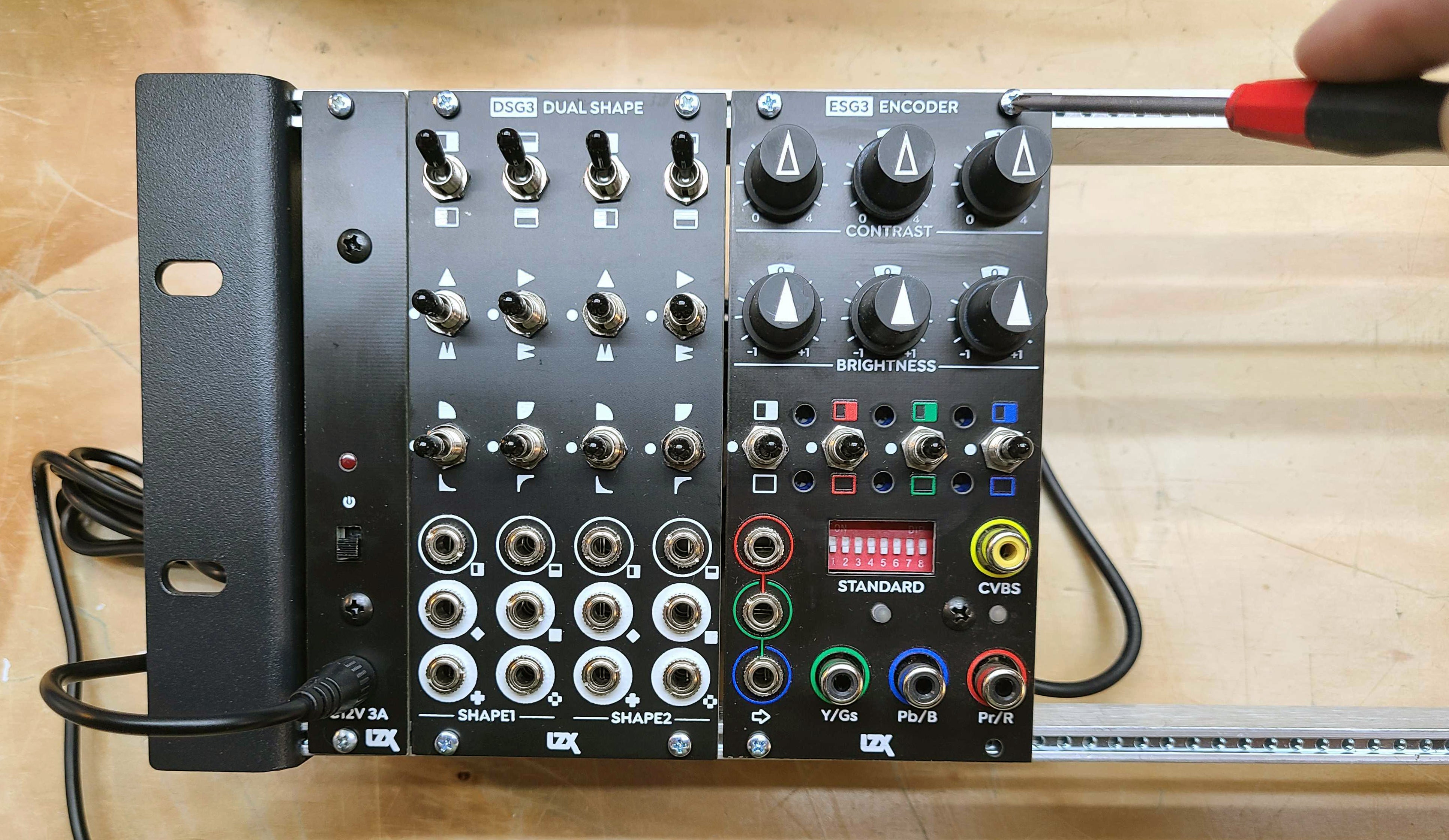
Secure the module to your EuroRack mounting rails using the screws provided by your EuroRack case provider.
Your First Patch
This patch assumes you have followed the module installation instructions above, and your LZX Modular system is powered on.
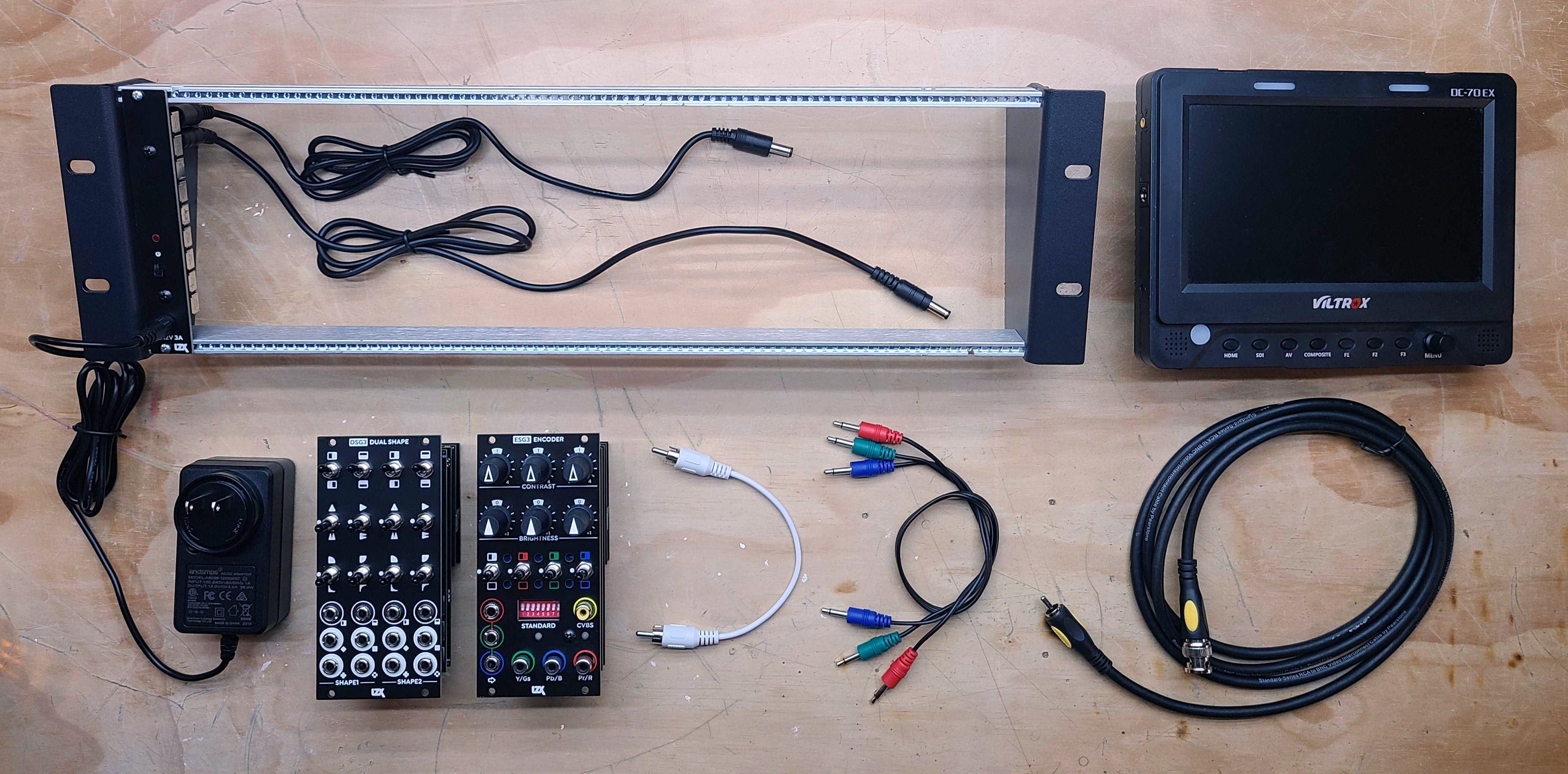
Here's what you will need:
- ESG3 Encoder & Sync Generator module
- DSG3 Dual Shape Generator module
- An RCA-to-RCA cable for composite video output
- A video display with composite video input
- Three 3.5mm patch cables
Initial Settings
All toggle switches on ESG3 and DSG3 should be reset to their center (middle) position. All knobs on ESG3 should be set to their detented (middle) position.
Turn all of ESG3's front DIP switches to their OFF position. If you want NTSC output, leave them all OFF. If you want PAL output, turn switch #1 to the ON position.
Connecting A Video Display
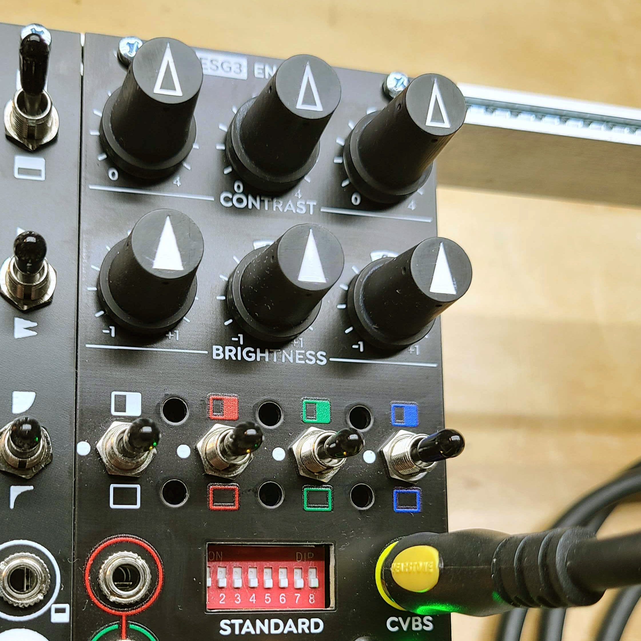
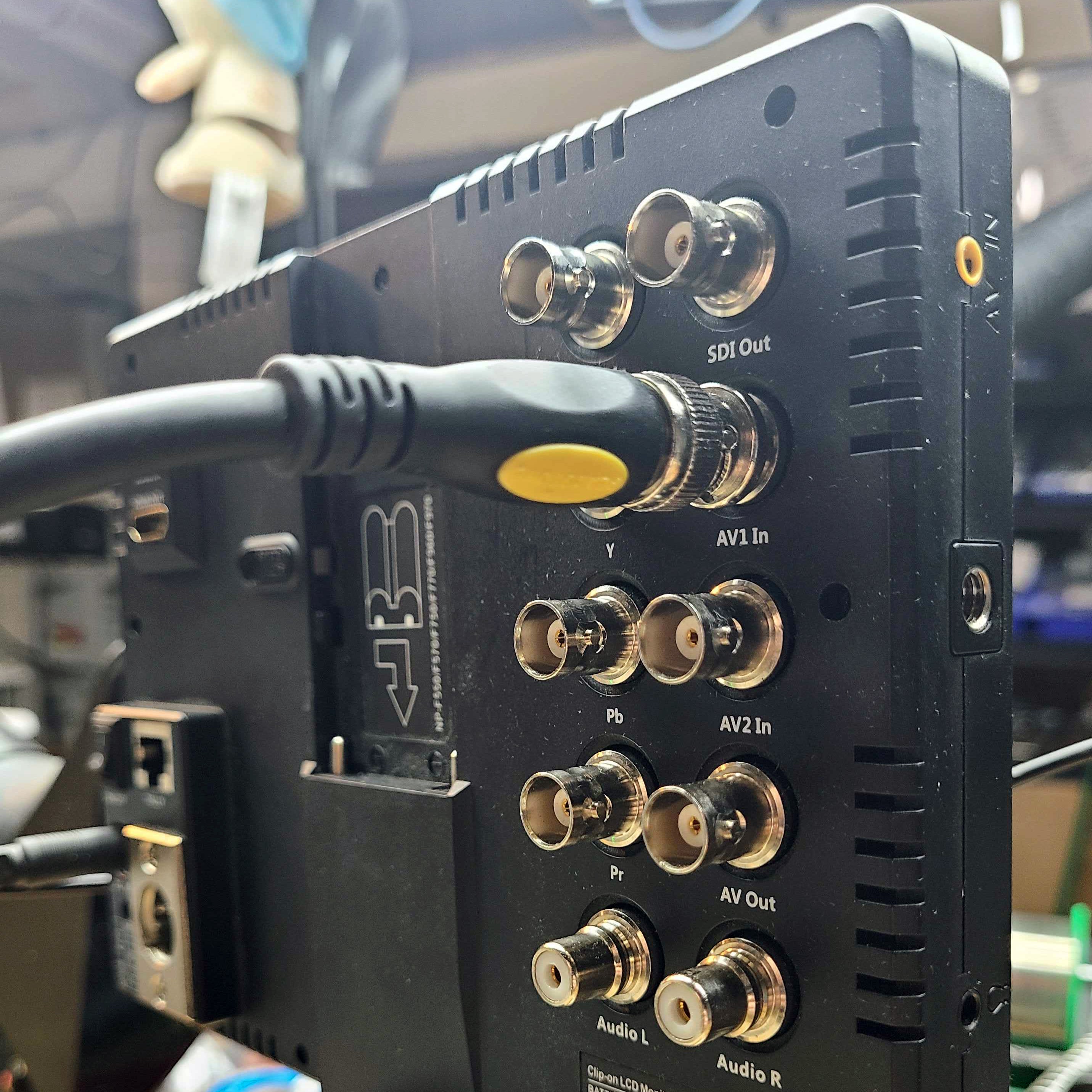
Connect your video display's CVBS input to your ESG3 Video Encoder & Sync Generator module's CVBS output.
Generating A Color Pattern
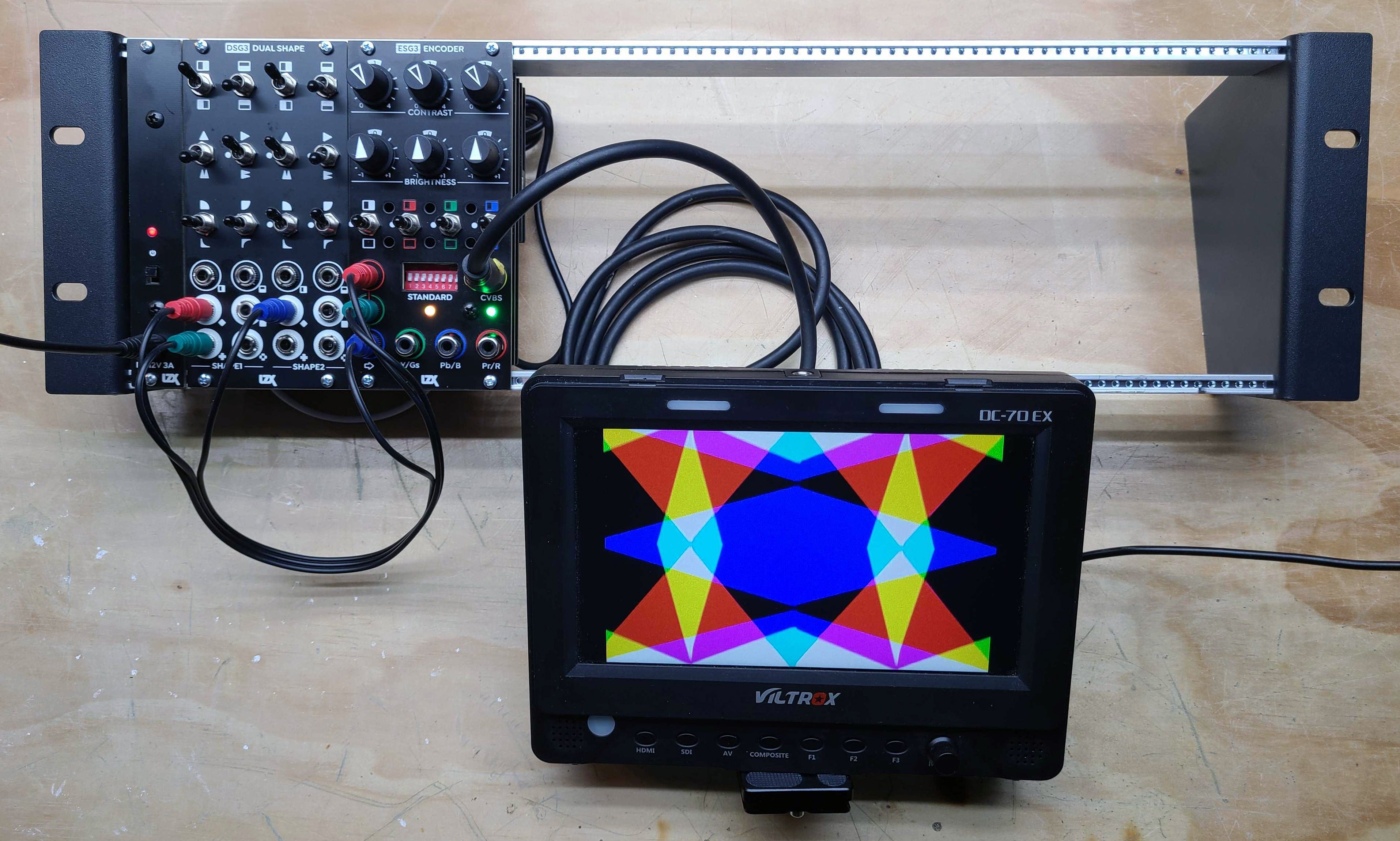
Patch any three of DSG3's eight outputs to your ESG3's Red, Green & Blue input jacks. Play with the knobs and switches on ESG3 and DSG3, exploring the capabilities of your patternmaking patch. Patch different outputs from DSG3 to observe different combinations.
Adding Complexity
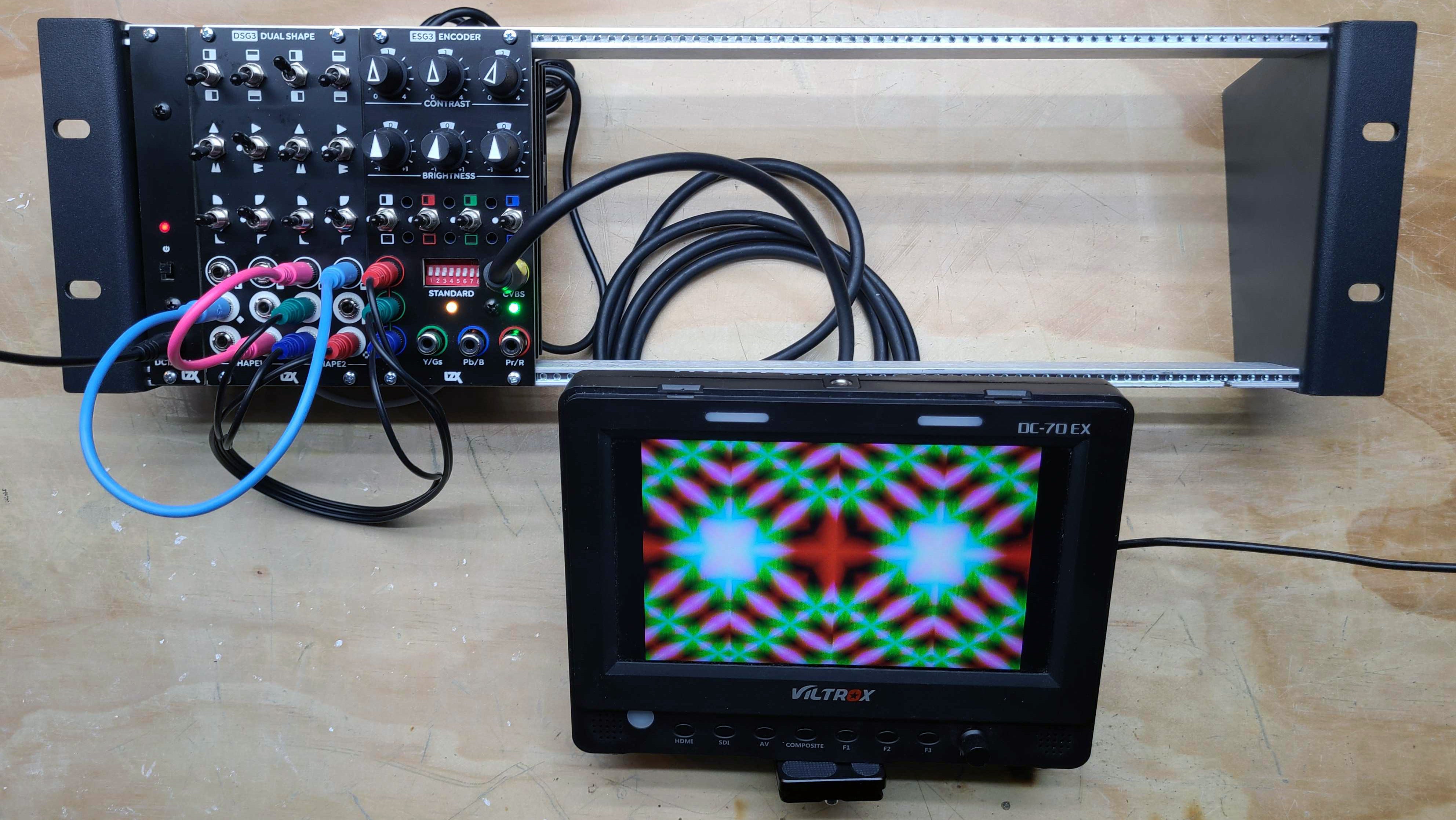
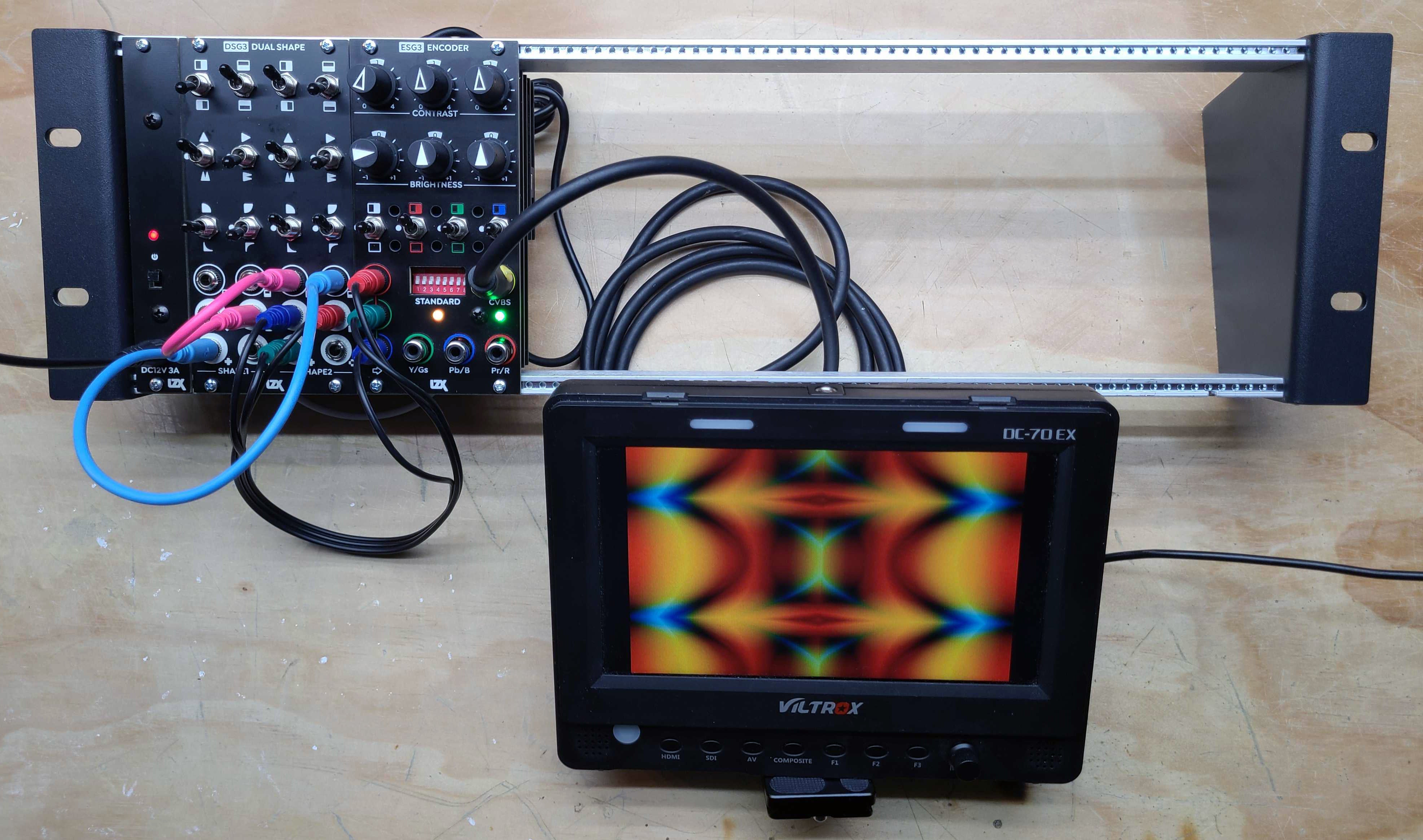
Next, let's make the geometry of your pattern capable of more complex results through series processing. Patch two outputs from DSG3's first shape generator, to the inputs of it's second shape generator. Now take your RGB pattern from the second shape generator's outputs.
Concepts
Generators
Ramp Generator
A ramp generator is a waveform generator which produces analog waveforms synchronous to the horizontal or vertical dimensions of the video screen. It is a common component of analog graphics modules, such as shape and pattern generators.
Voltage Controlled Oscillator (VCO)
A voltage controlled oscillator is similar to a ramp generator, only its frequency may be changed or modulated. A voltage controlled oscillator may be free running, or reset in time with the video sync to synthesize a stable pattern.
Frame Synchronizer
A frame synchronizer takes an external video feed and synchronizes it with the system's internal timing. A frame synchronizer is usually required to input multiple external video sources into your system like cameras and media players.
Functions
Modules often contain many analog functions. Some modules may have similar internal function blocks, but different strategies for allowing the user access to them.
Comparator
Also known as a hard key generator or 1-bit ADC (Analog-to-Digital converter) function. When the positive input voltage is greater than the negative input voltage, the output is 1 volt (White Level). Otherwise, the output is 0 volts (Black Level).
Clipping Amplifier
Also known as a soft key generator or wide range contrast processor. The output is created by amplifying the video source to create a high contrast mask with variable edge width.
Encoder
A video encoder takes 1 volt scale unipolar signals for Red, Green & Blue color channels, and performs all operations required to convert them into a video signal for display or recording.
Negative
Also known as a voltage mirror. The output is equal to the input voltage is subtracted from 1 volt (White Level).
Doubler
Also known as a saw-to-triangle waveshaper, the doubler is a combination of an absolute value function and clipping amplifier function.
Logarithmic Amplifier
An logarithmic amplifier changes a linear input voltage into an output with logarithmic scale.
Exponential Amplifier
An exponential amplifier changes a linear input voltage into an output with exponential scale.
Summing Amplifier
Also known as a Mixer. A summing amplifier adds two or more voltages to each other. The voltages may be unipolar or bipolar scale.
Minimum Value
A minimum value function compares two or more inputs, and passes the input with the least voltage to the output.
Maximum Value
A maximum value function compares two or more inputs, and passes the input with the most voltage to the output.
Absolute Value
An absolute value function inverts all values below zero and forces the output to be positive.
Standards
Electrical
LZX Modular proposes an interface specification for wide bandwidth analog computing instruments. It is optimized for, but not limited to: (1) generating and processing analog RGB video graphics in SD/HD resolutions, (2) affordable devices which are accessible to working artists and not just big studios, and (3) maximum patchability via a universal DC voltage range and high impedance connections.
Patchable Signals
Waveform generators, video sources, boolean logic, and control voltages all share the same voltage ranges and IO connectors. Cross patching different signal types is an encouraged use of the system.
Connectors: 3.5mm mono jacks Cables: 3.5mm patch cables Unipolar Scale: 0 to +1V DC Bipolar Scale: +/-1V DC Minimum Bandwidth: 5 MHz Input Impedance: 100K ohms
Video
0 IRE (Black Level) and 100 IRE (White Level) are scaled to the patchable unipolar range.
Logic
Inputs to logic gates, multiplexer controls, and other CMOS functions must have an analog voltage comparator frontend, for converting any voltage into a binary signal.
Comparator Threshold: 0.5V DC
Mechanical
LZX Modular is based on the form factor specified by Doepfer in their A-100 Construction Details manual.
In addition to conforming to Doepfer's standard, LZX Modular is designed according to the following dimensional reference.
Frontpanel Width: (HP * 200) - 12 mils Frontpanel Height: 5058 mils Rear PCB Assembly Max Width: (HP * 200) - 40 mils Rear PCB Assembly Max Height: 4370 mils
Video Timing
The current generation of LZX Modular supports 15 video sync formats.
- NTSC
- PAL
- 480p
- 576p
- 720p50
- 720p5994
- 720p60
- 1080p2398
- 1080p24
- 1080p25
- 1080p2997
- 1080i50
- 1080i5994
- 1080i60
Products released before 2020 supported 2 video sync formats.
- NTSC
- PAL
Troubleshooting
I suspect something is not working. What are some good troubleshooting steps to follow?
- Keep it simple. Simplify your patch to the least number of cables or connections that create the issue you're seeing. Sometimes this will reveal the problem. If you jump into more complex theories right away, you may miss simple answers, like a defective patch cable or a missed setting.
- Your 12V power supply or EuroRack power supply may not be supplying enough current. Underpowering your system can result in a variety of glitchy behavior. Add up the current consumption required by your LZX modules or by any other modules sharing the same power source, and verify that this is less than the current supplied by your power supply. If it is very close to, or greater than, the supplied current, upgrade your power supply.
- Try testing modules in isolation. Disconnect all modules from your system, and connect only the output module, such as ESG3, to the power supply. After verifying it works correctly, power up the next module. Keep going until your issue reappears. If the issue reappears near the power supply's limits, upgrade your power supply. If the issue seems to be connected to a specific module, focus on troubleshooting that module.
I am seeing my LZX Modular system's video output drop in and out on my video monitor or video recording device, resulting in missing frames.
- Your video device might be defective. Verify that your video device can display video signals from a different video source of the same video format, using a different set of video cables. If you see the same issue, your device is defective. Contact the manufacturer of your video device for advice on further troubleshooting.
- Your video cables might be defective. Try with another set of video cables. If your issue has been resolved with the new cables, your video cables were defective.
- Your video cables might be too long. Try with another set of video cables no longer than 2 meters in length. If this resolves your issue, use the shorter cables. If you require a very long cable run, you may need to add a video distribution amplifier to your equipment list.
- Your ESG3 module may be defective. If none of the above solutions work, check to see if the issue goes away when you adjust the Contrast controls on your ESG3. If so, does the issue return when you recenter the controls? If so, this is most likely due to a PCB assembly or connector issue, such as a dry or unsoldered pad. The issue can be resolved by service or replacement performed by a qualified technician at LZX.
My ESG3 doesn't work sometimes when I power my system on. When this happens, both frontpanel indicators are green.
- Your firmware is not booting under some conditions. This is most likely due to a PCB assembly or connector issue, such as a dry or unsoldered pad. The issue can be resolved by service or replacement performed by a qualified technician at LZX.
Test & Calibration
Many users like to perform regular service and checkups on their analog hardware systems. For many, the ability to verify a module is operating properly is useful for troubleshooting a complex system. For others, using electronic test equipment like oscilloscopes, multimeters and firmware programmers is part of their relationship to the instrument. With this in mind, we present models for both basic functional testing and advanced testing and calibration. We would love to see LZX Modular equipment in use several centuries from now, due to the diligence and care taken by its community of users.
Basic Testing
- Power supply capable of 1 amps or more of current at 12 volts DC (EuroRack, Generic Wall Wart Adapter, etc)
- A video display with Composite or Component video input
- At least three RCA-to-RCA 75 ohms video cables or RCA-to-BNC 75 ohms video cables (use the native connector type present on your display) less than or equal to 2 meters in length
- At least three 3.5mm patch cables less than or equal to 1 meter in length
- EuroRack module mounting rails, either inside a EuroRack case or a bare rack frame
- ESG3 Encoder & Sync Generator module
Advanced Testing & User Calibration
- All items in the Basic Testing Requirements list
- A second set of all items in the Basic Testing Requirements list if the test requires it
- A dual channel oscilloscope with at least 100 MHz bandwidth and two low voltage signal probes
- A multimeter with voltmeter and ammeter functions
- Metric and imperial small nut driver and screwdriver sets for module disassembly, reassembly, and trimmer adjustment
Firmware Programming (ESG3 & DSG3)
- Lattice HW-USBN-2B Programming Cable
- TagConnect TC-LATTICE-10 Programming Cable Adapter
- TagConnect TC2050-IDC-NL 10-Pin No-Legs Cable with Ribbon Connector
Compatibility
Do you have a compatibility issue to report? Please submit our form at https://forms.gle/y9FktKrRbMK1paRE6
A list of hardware verified to be fully compatible with LZX Modular. This list is far from extensive, and is only intended to communicate the results of testing conducted by the development team at LZX, in the LZX lab.
EuroRack Cases & Power Supplies
- LZX Vessel Case
- LZX Capsule Power
- TipTop Audio Mantis Case
- Arturia Rack Brute
- Malekko Power
Video Capture & Display Devices (SD/HD)
- Blackmagic Design Analog-to-SDI Mini Converter
- Blackmagic Design DeckLink Quad SDI PCI Card
- SEETEC P173-9HSD-RM Broadcast Video Monitor
Glossary
key
any video signal used to control a transition between two or more other video signals
hard key
a boolean logic signal which switches between two signals.
key generator
a module designed to condition an input for the purpose of keying operations
soft key
an analog voltage representing the mix ratio between two video signals
hard key generator
typically implemented as a differential analog comparator.
soft key generator
typically implemented as a high gain differential amplifier with black and white level clipping
chroma key generator
processes the chroma components (PbPr) of a component video signal, allowing key extraction based on Hue and Saturation of the video source
luma key generator
processes the luma component (Y) of a component video signal, allowing key extraction based on the overall brightness of the video source
multi level key generator
produces multiple key signals from a single source, and are often used as the frontend for colorizers and sequencers
component key generator
acts on one color channel at a time, but still includes the entire colorspace in its output function
window key generator
has dual threshold controls, either Upper/Lower or Span/Center
fader
a module which performs a transition between two video sources. typically it has a direct key input, without much local control over the key itself.
keyer
a module which has both a key generator and a fader or switcher
linear colorizer / multi level keyer
combines multiple faders with a multi level key generator function to produce a transition across more than two inputs