Reference Manual
MLT
Technical documentation, setup guidance, and patching workflows.
← Back to MLT overviewMLT
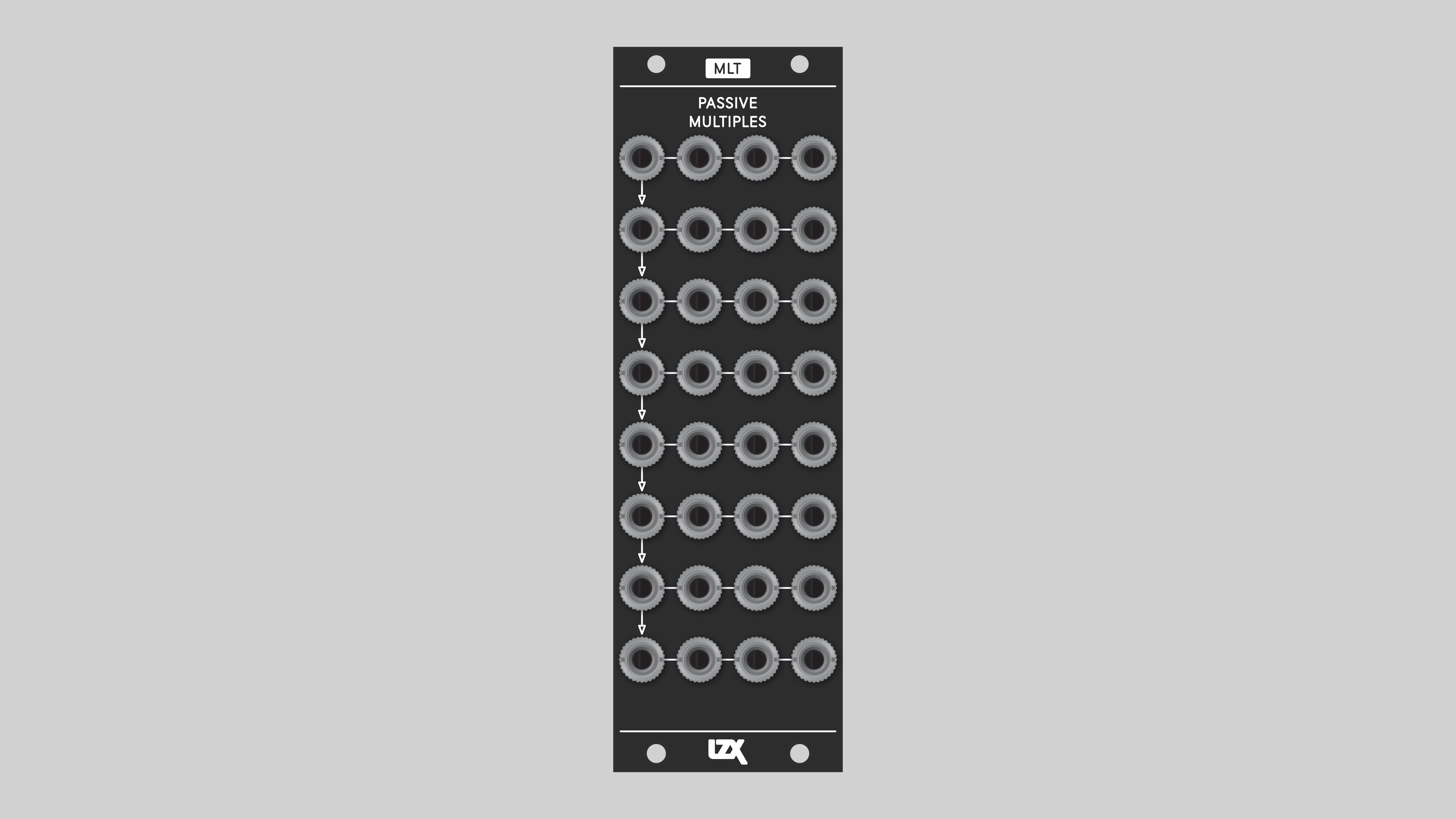
Passive Multiples
<!-- ## Overview -→
Key Specifications
Mounting Width |
8 HP |
Power Consumption |
None |
Power Connectors |
None |
Video Sync |
None |
Connectors
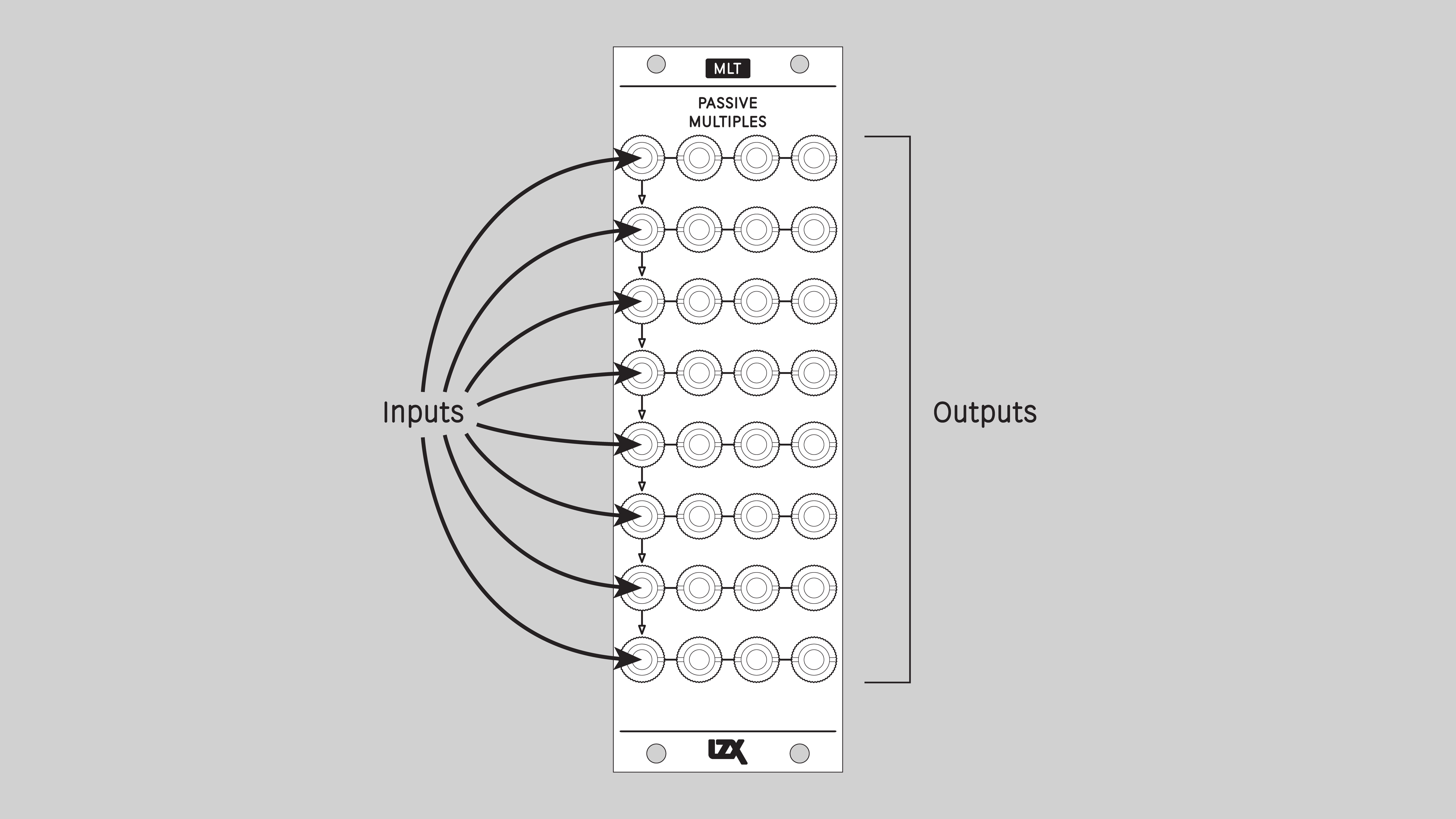
Operation
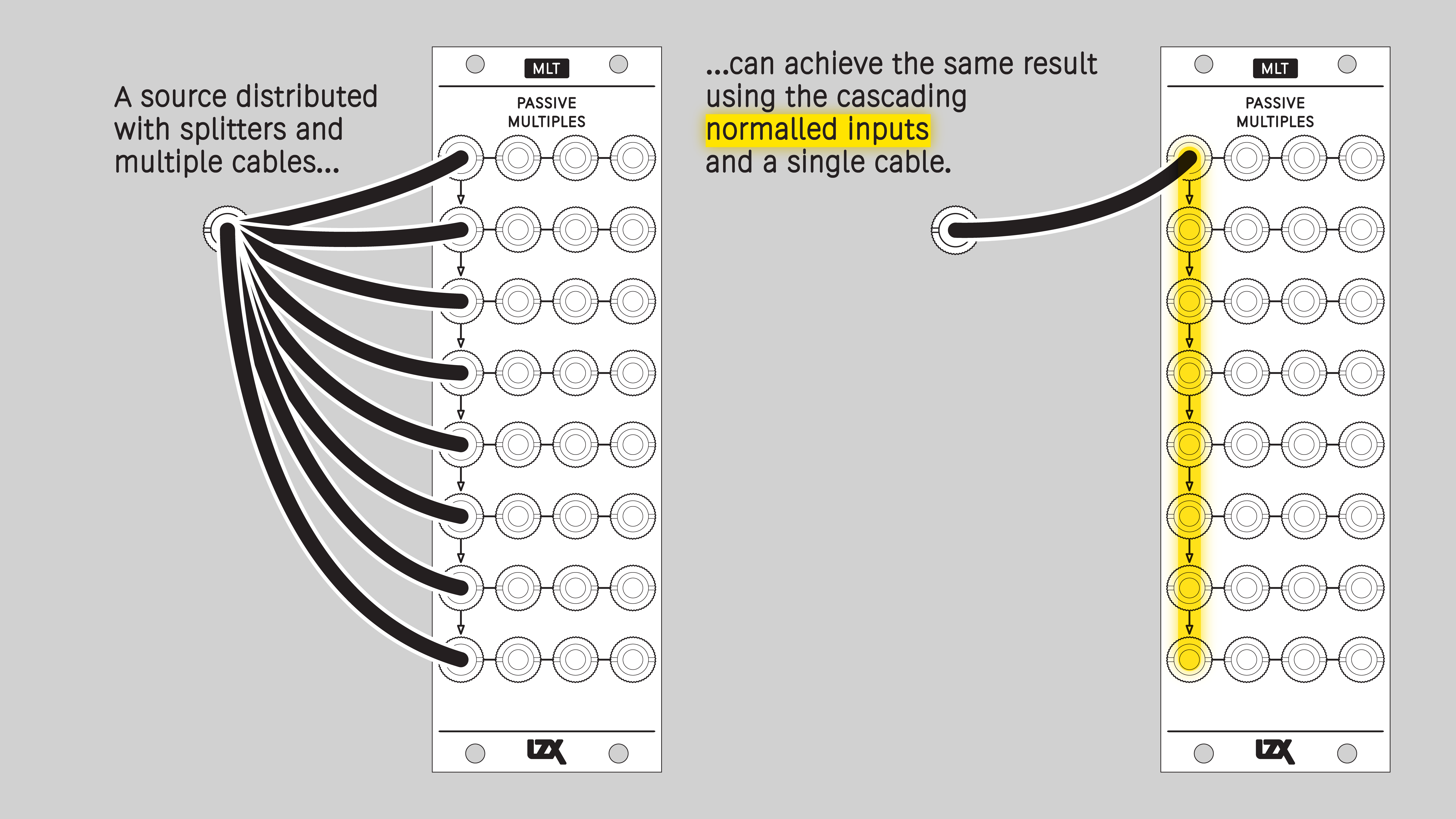
Understanding Cascading Input Jacks
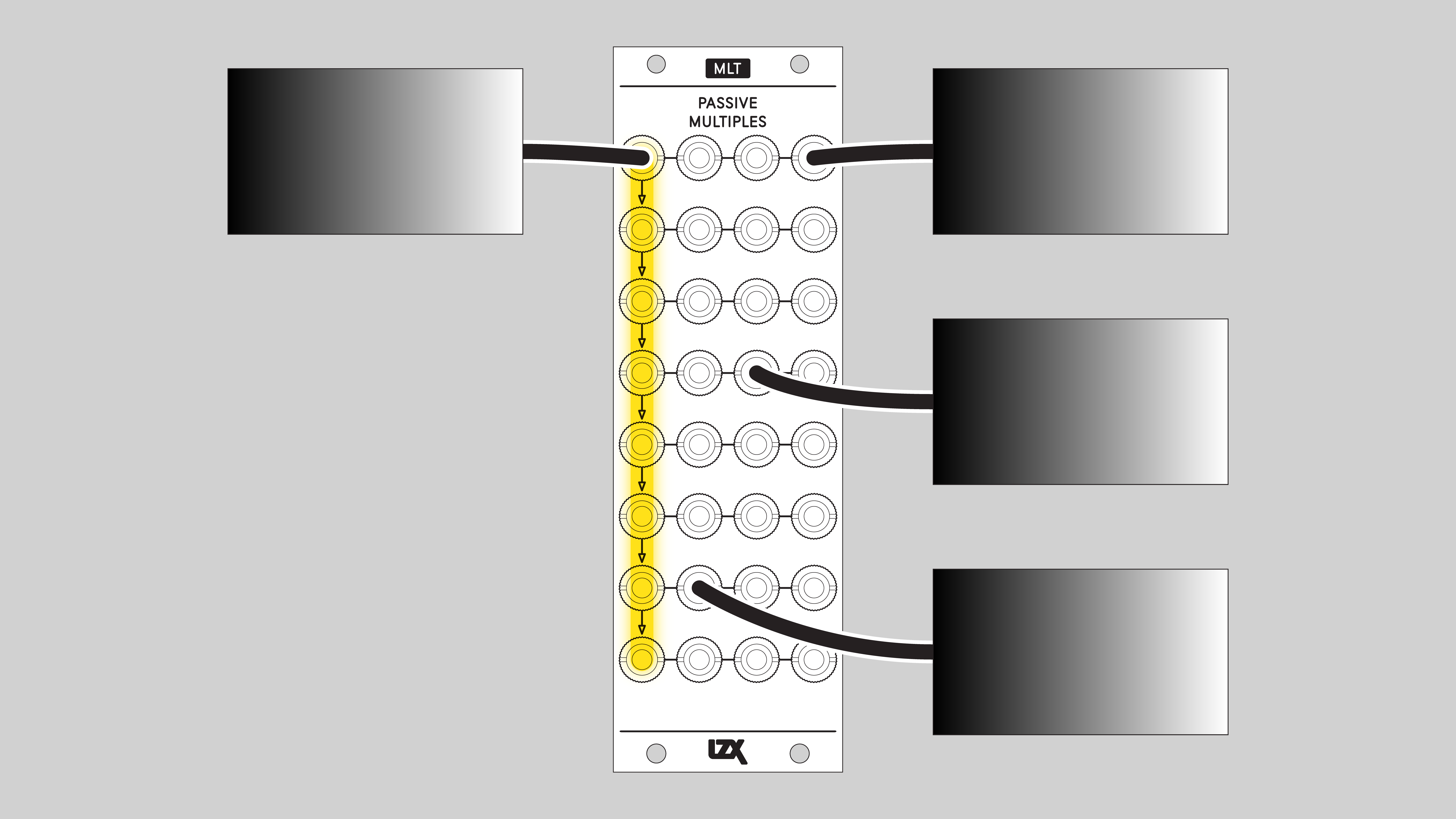
MLT uses switched, or normalled, connections between some of its input jacks. With no cable inserted, a signal flows down from one input jack to another. This connection is overridden when a cable is inserted. Normalled inputs are indicated on the front panel with arrows.
Example Patches
Installation
Requirements
-
EuroRack enclosure.
-
Two M2.5 x 6mm mounting screws, or screws provided or specified by the enclosure manufacturer.
-
#1 Phillips head screwdriver, or hand tool provided or specified by the enclosure manufacturer.
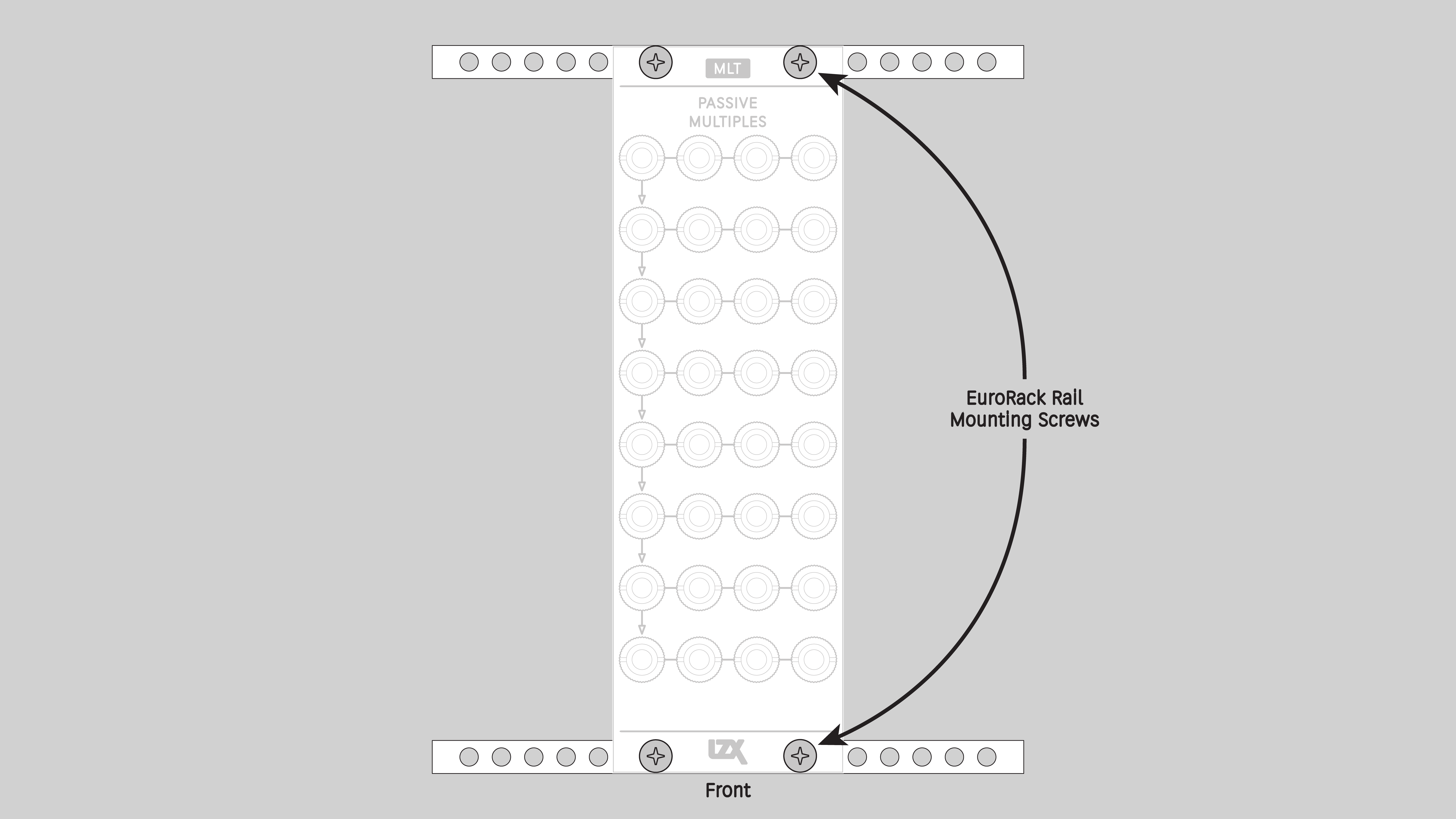
Procedure
-
Power off and disconnect the EuroRack enclosure’s power supply and any attached DC adapters.
-
Ensure that no mounting screws are in any holes in the area where you wish to mount the module.
-
Carefully test fit the module in the open space in the EuroRack enclosure. If it is obstructed by the enclosure or any internal assemblies, abort this procedure.
-
Mount the module to the EuroRack rails using all mounting holes.
-
Power on the EuroRack enclosure and start patching.
Full Specifications
<!-- === Technical Data -→
Mounting Width |
8 HP |
Mounting Hole Count |
2 |
Power Consumption |
n/a |
Module Width |
40.64 mm |
Module Height |
128.5 mm |
Product Box Width |
4 in / 101.6 mm |
Product Box Height |
2 in / 50.8 mm |
Product Box Depth |
6 in / 152.4 mm |
RoHS Compliance |
Manufactured with lead-free processes. |
Video Sync |
None |
<!--
| Manufacturer Part Number | |
|---|---|
Mounting Depth |
TODO mm |
Module Depth |
TODO mm |
Product Weight |
TODO |
-→
Maintenance
Keep your module free of dust and debris by performing periodic cleaning. Spots may be cleaned from the frontpanel with a microfiber cloth and isopropyl alcohol or other electronics cleaner.
<!-- ## Troubleshooting -→
Hardware Revisions
The hardware revision code is printed on the circuit board visible from the rear of the module.
MLT-RevA
Initial production version, February 2025
mlt_reva Schematic Diagram <br /> Download PDF
mlt_reva Interactive Bill of Materials <br /> Download ZIP
DIY
Downloads for the complete schematic and an interactive HTML Bill of Materials are found in the Hardware Revisions section above.
Partial DIY Components
The partial DIY kit from LZX includes the printed circuit board and front panel. The following components must be purchased separately from electronics parts vendors.
| Manufacturer | Manufacturer Part Number | Description | Quantity | Reference Designators |
|---|---|---|---|---|
Wenzhou QingPu Electronics Co., Ltd |
WQP-WQP518MA |
3.5mm Jack Mono Switched |
32 |
J1, J2, J3, J4, J5, J6, J7, J8, J9, J10, J11, J12, J13, J14, J15, J16, J17, J18, J19, J20, J21, J22, J23, J24, J25, J26, J27, J28, J29, J30, J31, J32 |
Assembly Instructions
This assembly job is recommended for intermediate level DIYers who are comfortable soldering thru hole joints in close proximity to surface mounted parts.
-
Mount and solder front-facing jacks.
-
Attach the front panel and secure it with mounting nuts for the jacks.