Reference Manual
P
Technical documentation, setup guidance, and patching workflows.
← Back to P overviewP Archive
Archived community reference. This page compiles related LZX Community forum discussions for P inside the new documentation site.
Related discussions are compiled below.
Community Discussions
Chromagnon Synthesis Concepts
Ahead of a demo video to show what Chromagnon can do, and in response to questions about how it works, here are some notes from Lars about the new LZX standalone synthesizer.
So to explain it compositionally, in a no-input case, it starts with ramp shape selection as the “scene”. You reach over to the right, set it to “triangle ramps” or whatever you like and then you select “Vector” if you want to process the ramps natively or “Shape” if you want to process them as a quadrilateral (4 quadrant mirrored AKA triangle ramps) space. Then you have XY controls, edge softness, etc. like a typical Navigator/Shapechanger based patch.
To change that shape, you modulate it either directly (with ambient motion generator or directly patched source) or you use the Modulation Vector, which allows you to define a 2D rotation for the ramps in parallel and then use that to displace the original ramps thru a mod matrix (the 5 buttons on the lower left). Imagine if you had a 2D staircase and that 2D staircase had dual VCAs feeding the rotation angle of Navigator–that’s what the Modulation Vector section is.
Now if you want something a little more wiggly, like an oscillator pattern, that’s what the “Fold” button does (Fold button on = Super Staircase = Chromagnon is complex shape generator).
Fold will add more density to the pattern (like Staircase does), whereas fold off allows for dimensional displacements (like this is where you’d patch luma for your Rutt Etra effect).
Right side buttons in order…
- HV/Ramp shape select (8 ramp shape options)
- XY Mode – this sets the main function of the instrument: Chroma gen/proc, Luma gen/proc, Vector (for ILDA or XY displays), and HV (for shape/pattern generation with ramps)
- Luma output source (these go thru a YUV to RGB converter, and then into the Porter-Duff Compositor as the Top Layer/Foreground)
- Chroma output source
- Porter-Duff Compositor (12 modes). These settings change the way the processed output and the input source are blending together, like a wet/dry composite. There’s a lot of analog logic and dual key generation trickery here, to achieve the complex RGB logic.
To break down button 2 a bit more, you can think of it like 4 different patches. You effectively have two modes for external source processing (Luma and Chroma), one mode for pattern synthesis (HV), and one mode for vector/laser synthesis (Vector). It changes the context in which the signals interact. Vector and HV mode are almost identical–just different ramp settings and VCA/Gain strategy. For example, in Vector mode Edge controls raster size. In HV mode, it is a high gain clipping function.
Thread Replies

so this is the layout for the keying section display?
there are 8 hv ramps (HV>),
4 described “patches” (>XY),
and 12 modes for the porter duff compositor (RGB>)
that leaves 3 options for both DST LUMA (XYK>) and DST CHRO (>RGB)

in the signal flow both the DST LUMA and CHRO have 3:1 mux
with the names of the buttons would make sense
luma
key, shape and max (assuming that is the 1v white)
chroma
src, xy, and none (assuming that is the 0v black)
I’m feeling some wheels clicking into place about this layout
it seems like this trick (seen in the video below) I stumbled onto the other day with the v440 mixer and switching between two sources luma/chroma combinations was not a coincidence but maybe mental preparation for chromagnon
I was looking at this and thinking a similar thing just a few weeks ago. I didn’t bother working out all the details, but I realised a Chromagnon would work better for me than a whole lot of other modules and/or external devices, like a V440. Every time I look at that mixer, I come to the same conclusion. This signal flow/generation/processing explanation confirms it. Thanks, Lars.
However, the real big selling point, for me, is the power and case. Clean power with a stand-alone case wins. If I can also rack it on 84hp rails, that’s another winning feature. Chromagnon looks like it has all of that, but I’ll hold back my excitement until its available from a UK shop.
Thanks.
Neat!
Any idea when the first video will drop?
The first video will drop after a complete Chromagnon unit is finished and delivered to Johnny Woods. Right now the team is finishing TBC2.
Super stoked! I’d love to make some examples too when my first day pre-order arrives. 

So helpful! The anticipation has been stoked.

Q: What is this modulation vector?
A: “That’s “orbital displacement.” The modulation vector has Sin/Cos output, so if you feed an LFO then orbital displacement will cause the shape to position itself around a circular path. You could do something similar by feeding a quadrature LFO sin/cos into Navigator XY. Or using navigator 1 out to modulate XY of navigator 2. Something that’s not implicit from the panel is that there are four states for each modulation vector button. off/red/green/yellow = off/x/y/both.”
A note on Chromagnon’s video i/o:
It will support “240p/288p/480p/576p/720p/1080p30. We could even add some timing profiles to match some weirder formats as well. On the rear we have an 8 position dip switch. 1 switch turns sync auto-detect on/off – with it on, system genlock switches to match the format of the TBC input source if no sync input is present. Auto-detect is always on for the sync/genlock input, and that overrides any TBC input source. The other 7 bits select up to 128 different video standards. So in the case of using Chromagnon with no input, or as master sync gen, you will select your default video format with these switches.”
1080p video feedback possibilities ermahgerd!!! Can’t wait.
Does this mean it will sync to arbitrary rates that fit the data rate but are not specified? If not I would love to see standard SMPTE rates like 24p, 23.98p, 29.97p, 59.94i, 59.94p
I wasn’t familiar with “Porter-Duff”. Upon googling I found this image (it happens to have 12 examples  )
)

Will most of these compositions be essentially possible?
This corresponds with the 12 compositor modes available in Chromagnon.
Thanks for clarifying, very exciting!
Lars, quoted from FB comments, says:
The number of frame synchronizers in a system you need is equal to the number of input sources minus one. So with Chromagnon + Visual Cortex, you can have two external sources. One is the master timing reference, and the other is frame synchronized by Chromagnon’s TBC. Key to the Automata series concept is that all units include a TBC and a 2:1 RGB function. Meaning each device can mix itself into an external source. RGB inputs are separate from the decoder/TBC section. Yes, you can feed the outputs back through the TBC in feedback mode while still using the RGB inputs.
Visual Cortex locks itself to the timing of an external source. That external source can also be fed to an input decoder, so you can patch the video through the system. Visual Cortex has to slave itself to the external timing in order for this to work. Chromagnon locks itself to the timing of an external source via the genlock input (or not, can be free running). Where it differs is that the input decoder has a TBC/frame sync this time. So the external sync/genlock source and the external video source don’t have to be one in the same. Meaning we can sync Chromagnon #2 to Chromagnon #1, while both of them can frame sync an asynchronous external video feed, resulting in two synchronous external input channels. So technically Chromagnon has two external inputs (Genlock/Sync Input and External Video inputs). Whereas Visual Cortex only has one (Input Decoder and Genlock/Sync Generator must be the same).
so with a visual cortex, chromagnon, TBC2 setup you could have 4 external sources?
Correct. TBC2 and Chromagnon share the same video input platform.
oh wow things are going to get wild
^Agreed!! Had to jump on the pre-order bandwagon!!!
It’s stated that the chromagnon will replace the functionality of the polar fringe, yet no joystick, I’m not all too sure about how this will work. So I’m wondering if this is going to be built in to the modulation section. Also does this mean an eventual discontinuation of polar fringe?
here is some info from lars on facebook
"Note that with Chroma (PbPr) to XY inputs, the shape generator is producing a chroma key.
Since the XY processor performs at video rate bandwidths, it can process the PbPr (Chroma) channels of the input video source as UV colorspace (which is a two dimensional plane.) For example, X & Y Position become PbPr offsets (hue selection). Rotation becomes Hue shift, and Gain becomes Saturation. So to process chroma we first convert RGB to PbPr, then feed those to the X & Y inputs. Then we take the X & Y outputs and convert them back to RGB (along with a luma component). This is complex in the block diagram, but easy on the synth – you just select “Chroma” as the “Vector Mode.”
So imagine this (UV at constant luminance) as the “2D plane” that is being processed/generated by the XY Processor, when we feed in Chroma as the vector source.
Yes, that is the key idea behind this instrument! General purpose XY processor (analogue computer style) with a lot of complex interfacing that allows its use as color processor, colorizer, shape/key generator, vector rescan driver, etc. I hope it gets people to think about how all of these applications are driven by similar math at their core. There is also a Polar-to-Cartesian processor in the XY Processor (the “modulation vector.”) This can take angle and distance inputs and give XY outputs. The Angle input can be used for a direct voltage to Hue function, which allows for a Luma-to-Hue map colorizer."
Starting to wonder why all the juicy info gets posted to Facebook? Thank you to the folks who are reposting it here, I’m sure I’m not the only one ethically opposed to having a Facebook account. 
 (I was on there a regrettable 9 years)
I think it’s because people are on it all the time anyway. It’s designed to be addictive, after all.
An addiction my life is so much better without now. Don’t want to preach or belittle anyone here, but the idea that Facebook is something we need in our lives is an illusion, and I’ve been super great without it for over two years.  The fact that LZX has this forum site is most supreme, considering the current era of some companies main presence only being on Facebook or Twitter. Thank you!
Totally understood, but used as a tool and not a portal to ego, facobook can be used as a forum for all the forms you are interested in. In my opinion of course. Personally i use it for many types of synthesis discussions and or informational groups, audio, video synthesis, drum machines. Sound design. Anything can be a tool or a distraction, it’s how it’s used. With all due respect. 
A little update for those not on Facebook; Lars posted,
“RevB units were built and passed all tests so far. This is after a lengthy review of all the RevA boards over the Summer. Jonah, Nick and the assembly team have been kicking ass on that and just getting on top of production prep. I’m holed away still with my software project for tbc2/Chromagnon/mempal, and almost ready to show it off. This week I also need to dig in to the RevB review, during which I hope to start showing some video.”

Austin James just asked a couple of questions regarding the #Chromagnon’s 1080 output & it’s composite output on the FB page, I can’t copy the text so here’s a screenshot.

@LILWILLY, you beat me to the line 
i took the robbertunity
Note to self, posts must be 20 characters long 
Some ILDA ideas from Lars:
“Radiator into Chromagnon adds an additional analog rotator/processor/recolorizer to the ILDA signal chain. So you could use it to add an additional rotary access with direct displacement via audio and CV.”
“…there are multiple YUV/RGB converters in there. It’s going to process whatever it’s fed as continuous 0-5V RGB and +/-5V XY voltages. There’s all sorts of neat tricks. For example you could use the chrominance of the RGB channels as a Cartesian displacement vector for the XY path.”
Hi I think I saw something about being able to scale the output to an oscilloscope when working with x-y graphics. Can you also invert the output or would I need to do that elsewhere? Im looking for an oscilloscope but some has a z axis that lowers the brightness with higher voltage.
I believe the gain controls for X/Y/Luma do not invert, so you would have to invert the signal after Chromagnon.
Am I understanding correctly, that I would be able to connect a video source such as a VHS deck as an input to Chromagnon without a TBC in between, and it would time base correct it for a clean picture?
Chromagnon incorporates its own TBC at the input, allowing you to send in full color video from signals like a VCR.
How easy would it be to do the camera-at-a-screen feedback workflow on Chromagnon? The one the Vidiot is known for.
More specifically, would it be possible to have a chain like [external video in > Chromagnon processing > video to screen > camera > feedback into Chromagnon > capture solution out]?
It seems like it should, but I’m not 100% able to tell from the info that’s out there.
If you’re planning to work with Chromagnon as a standalone unit, it would only sync to one external video input. Your second camera wouldn’t be synced to Chromagnon when you try to feed it back into the module. Probably would still look neat as a feedback source but you’d need to use something like the upcoming TBC2 or other means of genlocking your equipment to get additional synced inputs.
I’ve had pretty good success with using Extron VSC700 boxes as a cheaper alternative for full color synced inputs and have posted a few times on the forum about them.
EDIT: Oh wait, that’s not quite correct–I’ll eat some of my words here.
Since there is a RCA genlock input on the back and an external video input on the front that feeds into a frame synchronizer, you could feasibly loop your external video into the genlock input to get Chromagnon synchronized to that. Then put the other source into the external video input which will be frame synchronized.
You’d need to loop the external video going into the genlock input through the other RCA sync out connector and use some other type of video input module like Cadet III to condition the signal before patching it into Chromagnon. A RCA to 3.5MM adapter would work if you could strip the sync off the signal before patching it. Things might be a bit screwy otherwise.
If they’re asking about a set-up possible with Vidiot, I think they’re actually referring to a simple, single camera situation, no? So the signal flow would be:
Camera pointed at monitor > Chromagnon > Monitor + Capture
Processing possibilities are of course different than Vidiot, but that should work just fine.
And, indeed, since Chromagnon has multiple outputs — which I assume, like Visual Cortex, can be used at the same time — it will be easier to monitor and capture simultaneously (not that it is hard to make that happen with Vidiot but it does require something to distribute/pass the signal externally).
I should have clarified, I was thinking about combining that single camera workflow with an additional external video source. So a seed video goes in (such as gradient stills), gets processed, then goes back in as a feedback source as well.
Ah, okay. Well then, yes, you would need a second device to get that second external input into your system (same as you would with Vidiot).
Sync won’t really be as much of an issue with Chromagnon (as it is with Vidiot) because its external input has a built-in TBC.
1 video mixer at the end of the chain mixing/keying feedback with output
2 video mixer in front of chromagnon mixing/keying between feedback and source
3 take a 1/8 LZX standard video signal into one of the many video rate modulation inputs (assuming you’ve got modules that produce those signals)
4 camera -> mult -> chromagnon sync, dirty mixer A channel
still source -> dirty mixer B channel
dirty mixer out -> chromagnon video input
because things are sync’d together I would imagine you’d get the result you are after with this! I could be misunderstanding how those two inputs work with each other though
those would be the places that I would start messing around with that kind of workflow
Follow up question since you guys are so helpful and I’m struggling with capture options. Chromagnon has distinct Chroma/Luma/Shape modes. What type of workflow should I look for to run a single video through Chromagnon multiple times?
For example: [external video > Luma pass through Chromagnon > (record) shape pass > (record) Chroma pass > digital capture]. I suspect you could get amazing results from varying the order of operations and compositing modes on Chromagnon. But I can’t think of an elegant way to do this.
Something like [DVD player > Chromagnon > Ambery analog to HDMI convertor > Atomos Ninja 2 > computer > burn DVD > repeat]. That sounds too slow. Or maybe two shuttle recorders, rotating which is the input and output?
What type of workflows have people used for this? Anything from dirt cheap to primo…I’m stretched on budget but willing to save up for upgrades eventually. It’d be a shame not to take advantage of 1080i60 component outs on Chromagnon.
It might be easier to use a source that also records, so you can switch between your recorder and source in the chain. For example, 2x Atmos Ninjas, or a DVD recorder and a DVD player, or two laptops, or an Andor and a laptop, or any combination of these.
Maybe better to continue this discussion in one of the capture threads, as Chromagnon isn’t necessarily relevant to the methodology. You could apply this workflow to any processor.
So I’ve been thinking about how to use TBC2 and chromagnon to distribute sync between two cases. TBC2 has an rca sync out, so would sending this output to chromagnon on its video input sync the two cases?
I’m going over the 12 compositor modes and trying to match them up with the examples posted.
this post is showing some interesting data about how these modes will work

Is this the way the modes are laid out?
I’m assuming “clear” should be “add”
going over the data and matching the names up really helps be able to spins some more wheels about chromagnon.
I’d like to do a module layout with graphviz to approximate the navigator,shapechanger,staircase,polar fringe,mapper layout chromagnon can be.
I’m having a hard time fully understanding the polar fringe (is it used in the 12 compositor modes?) mapper (is it in the RGB to YUV conversion?) and staircase (I’m reading the 2d staircase explanation but don’t really get it) modules places in the patch.
I’m excited to understand it better!
also in preparation for the chromagnon I think it makes sense to try making a single modulation source that gets sent to many places in a patch. I personally haven’t really used that technique yet.
Hello all, on the fence about diving into video synthesis for some Rutt Etra visuals. I have a 12u on normal eurorack. Would the Chromagnon cover all the territory in the example patch on this site? Aside of course from the cctv and XY display? If not, what would I be lacking?
Chromagnon provides an all-in-one vector rescanning workflow. You would use the X/Y/Shape outputs (which will have rear panel trimmers to tailor the output to your vector monitor) into your X/Y/Z inputs.
More from Lars about the compositor:
[Chromagnon’s] Porter-Duff compositor is a 2-channel RGB mixer driven by two separate key sources controlling the gain of each channel. The key sources come from a few multiplexed min/max and summing amp circuits, so all the Porter-Duff logic is created there.
When both alpha channels are active, I expect a lot more negative space in the resulting composition in comparison to what we’re used to with raster patterns – since you have a multitude of ways to constrain two sources onto a black backdrop, and can easily avoid the “full frame wiggly rainbow square” look.
What I was trying to say was: avoiding the “full frame wiggly rainbow square” look. is overrated! 
has Memory Palace similar power needed
to a Crohmagnon?
- 550 mA +12V
- 50 mA -12V
- 0 mA 5V
Chromagnon could pull as much as 1.5A (1500mA) on the positive rail. This is still an estimate and is on the high side of the possible range.
Was curious about Chromag — is it possible to combine the feedback path/mode with external inputs, or have the two interact in any way? Also, is there a way to switch between feedback and external input modes via CV (or USB)? Thanks 
Feedback is considered an external input, so you wouldn’t be able to combine it with incoming video. Input sources are only selected manually, not via CV or USB.
You could do this with a video mixer, I’ve heard. Use the mixer to mix the Chromagnon output and the external video, then plug the mixer output into the Chromagnon input.
Definitely! You could even put other devices into that feedback path, too.
Oh yeah, great idea. I wonder if there’s a mixer out there that could work in this instance, while still preserving Chromag’s HD signal path? 
The V4EX / V8EX can accept HD Component over the VGA connector with a breakout cable I believe.
Awesome. That sounds like a pretty dang powerful setup.
This is true, and often upscales the input coming in quite significantly, as it’s a full rgb signal, instead of composite. Really makes a difference when going hdmi out on the big screen on a proper cinema (no pun intended) projector…
Moral of the story, component out wherever possible.
The Chromagnon RGB inputs use the 1V LZX modular video standard. Some folks have used Extron gear (as illuminated in other threads) to send RGB signals directly. TBC2 has an optional VGA expander, but you would have to convert VGA to component if using only Chromagnon.
Puzzled by the signal flow graph…Chromagnon’s TBC section is separate from its RGB in/out, right? So if I wanted to use it as both a synth/processor and an input/output encoder, I could?
For example: plug Chromagnon RGB outs into other video modules, process process process, send the signal into Chromagnon RGB ins, then capture out of Chromagnon’s YPbPr?
Could I plug an external source into Chromagnon RCA, take from RGB out, process it with other modules, send it back into the RGB in, process it with Chromagnon, then capture from the RCA out?
It is a synth/processor with a single input section and a single output section. It is not a combo TBC module + output encoder module with separate IOs. The YPbPr/CVBS inputs are just one of the ways to use the input section. If you patch into the RGB inputs, it will override anything going into the YPbPr/CVBS inputs.
If you are using Chromagnon as the base for a modular system, you would not use it like you would use a traditional Encoder + TBC in an LZX system. It’s a self contained voice, and any modules would expand the internal section (represented by the 9x analog controls/CV inputs, HV outs, etc. – that is, the part of the signal path between the video input and video output.)
Could I plug an external source into Chromagnon RCA, take from RGB out, process it with other modules, send it back into the RGB in, process it with Chromagnon, then capture from the RCA out?
If you did this, the external source would be overridden/detached when you patched back to the RGB inputs. You could patch the RGB outs through other modules and then feed them back into the CV inputs though, to create parameter feedback. You could patch the HV outs into other modules, create shapes, then use those as inputs to the CV modulation as well.
That makes way more sense. So the workflow of [Chromagnon > RGB processing > HD output] will not work without an additional Automata instrumen or a future output encoder.
So if I want to expand on Chromagnon without a second Chromagnon, CV modules are the main thing to add for now? The HV outs are basically like a Shapechanger/Navigator output and would require an output encoder. I’m very curious to see what this CV feedback would look like, though.
For a “self contained Chromagnon system” you don’t need additional encoders or TBCs (video IO), but any generator/processor modules (DSG3 Dual Shape, DWO3, Dual Osc, FKG3 Keyer, SMX3 Matrix Mixer) would be great expansion options.
So there are RCA sync input and output jacks on the back?
On the front panel graphic, I see a lowercase “s” on the TBC RCA jacks … “Y/Gs”. I presume this is sync.
Can Chromagnon sync to the incoming component signal?
What is the RGB standard for the RCA inputs to the TBC? I assume it’s 1V p/p. Is RGsB sync on green supported?
Is it possible to use the composite RCA jack as a sync input? RGBS?
Thanks!
Yes.
Yes.
Study this diagram first:

Its front panel YPbPr inputs go directly to a TBC so not in the way you’re thinking. Even if you mult the Y from a YPbPr signal into Chromagnon’s rear sync input to genlock it from that and then also into the front panel YPbPr inputs, it’s still going through a frame buffer before being passed to the next stage. If your goal is to have Chromagnon genlocked to an external source and input a YPbPr signal into its 3.5mm RGB LZX 0-1V standard connections while bypassing the TBC, you would need a separate input decoder module. Basically, mult your Y from a YPbPr source into Chromagnon’s rear sync input and then decode your YPbPr into RGB LZX 0-1V standard with a HD YPbPr input module that doesn’t exist yet. There are SD versions available like Syntonie’s VU003 for now.
Not sure on first question but second one, yes that’s the meaning of “Y/Gs”. It’s still going to go through a frame buffer though if you input RGsB into its front panel connectors. A separate RGsB input decoder module that doesn’t currently exist would let you bypass the TBC and plug directly into Chromagnon’s RGB LZX 0-1V standard connections, provided you had multed the Gs through to Chromagnon’s rear sync input.
Dunno but that might be useful! It would only allow for SD timings, presumably.
Thank you @rempesm –
I understand that the RCA input will always go through the TBC, delaying the source by one frame regardless of whether or not Chromagnon is genlocked to the source.
I do want to bypass the TBC so I am trying to figure out my options. Getting a lag-free RGBS signal out of a computer and into Chromagnon may be challenging. A YsUV to RGBS converter would do the trick, but they are probably unobtainium. Extron used to make one, back in 2009.
https://www.extron.com/product/cvc300
Maybe I can use an HDMI to DVI-D cable and this Extron converter?
BTW there are a couple of YUV → SCART converters available, but A) I think the voltages are not what Chromagnon expects, and B) I do not relish building a SCART breakout cable.
Just plan to use the YPbPr TBC inputs for your external video source – you’re trying to fit a square peg into a round hole, when there’s already a square hole! 
I’m sorry, but getting a “lag free” signal out of a computer for quite literally anything for all intents and purposes is impossible by the sheer nature of how digital systems work. More importantly, it’s right in the territory of people sweating the purity of the copper in their audio interconnects. Not a single human on earth can hear the difference in copper purity, no matter what an audiophile magazine will tell you.
The true answer here is obvious. You’ll have to sign up for a computer to brain interface as soon as possible so you can negate the latency of your eyes processing the incoming photons 
Lag matters if you’re syncing to sound or doing feedback, and comparing trying to iron out multiple frames worth of lag to copper purity purist audiophile madness makes little sense.
For those trying to sync up their patch to an audio source like a synth that uses pitch and gate CVs, one way to cut lag is to mult the pitch and gate CVs (filter cutoff CV very relevant too), and scale those voltages into whatever part of one’s patch that they care to modulate. This cuts out the “audio synth lag”, so that your video synth and audio synth are firing at the same time.
Btw, Really excited about the Chromagnon! I was looking at the front panel last night  . What did I Preorder!?! Can’t wait to run some feedback through it!
Did this video drop? I’ve been off and on in terms of searching. My apologies if the answer is blatant, I’m late to the party…
The production schedule suggests “not yet”. Note that FKG3 was in there until very recently, but now its shipping. Also note the warning highlighted in yellow.
…thats a new “yellow”, I’m ready for it. Keep up the good work folks. The synergy isn’t just locally generated - we got you
I’ve been paying attention to LZX since the first generation, but I needed a size of 16: 9 instead of 4: 3 because the purpose is to capture it on Mac and make my music video.
So I gave up on it and 10 years have passed. And recently, I heard that LZX supports 1080p output, and I’m considering introducing Cromagnon.
Please let me ask some questions related to that.
These are very rudimentary contents, so these were likely answered in the forum already,But I couldn’t find it. I’m sorry if there are duplicates.
Q1:
Why does LZX not introduce modern resolutions such as 4K, 6K, 8k, but introduce legacy resolutions of 1080p?
Due to my lack of knowledge, I expected that Cromagnon would be equipped with an HDMI output port and could output resolutions up to 8K.
Is it a technical issue that LZX does not introduce today’s resolutions? Or is it a ideological issue?
Q2:
I was wondering if there are many 16: 9 size videos made by pre-HD system on LZX’s Youtube channel etc. Are those online videos capturing the 4:3 SD output from LZX on a computer etc. and then forcibly stretching it sideways?
Q3:
I’m interested in the Orion series, especially the fortress, in addition to Cromagnon, but will the Orion series continue to be produced in the future?
Also, I’ve seen vague information about whether the Orion series supports HD. Is it possible to input the video output from the Orion series to Cromagnon and then capture it on a Mac in HD?
Excuse me for the beginner’s question.
Aspect ratio is a feature of the display device. Once you get the video into a computer, you can use whatever aspect ratio you like.
Some video players, like VLC, will let you override the ratio set in the file. The default settings on all the “smart” TV sets I’ve seen seems to be to use 16:9 regardless of the broadcast ratio. However, it may be possible to change this in a menu option.
Many videos created using LZX modules that I’ve seen use 4:3, but some of us prefer 16:9. I also like upscaling to HD and applying other post-production transformations. For example, I like cropping the image to get cleaner edges, then adding horizontal and vertical mirroring. As the starting point is SD video, I actually downscale to get HD. If I did this starting with HD video, then I’d get 4K without any scaling. Adding another level of mirroring would give 8K. However, I don’t yet have a 4K monitor, so I don’t bother. HD is good enough for me.
Everyone has their own post-production style. That’s why so many of us use a video editor or something similar.
As for LZX hardware resolution, I think that may be a technology issue. Eurorack PSUs in the past struggled to provide enough power for SD modules, nevermind HD. Gen3 solves this by supporting 12V dc supplies.
However, I think HD is the maximal possible resolution. That’s a limitation of component video. To go higher, you need to go digital.
ffmpeg -i pc.mp4 -s 1440x1080 pcO.mp4
ffmpeg -i pcO.mp4 -vf "scale=-1:1080:flags=lanczos,setsar=1,pad=1920:1080:(ow-iw)/2:(oh-ih)/2" pcU.mp4
I use these two ffmpeg commands to go from 640x480 > 1440x1080 then pad to 1920x1080
If the source absolutely has to stay in 4:3 this is the easiest way for me currently
in my system I use an extron 300a to go from component output to HDMI and it also upscales however I want. The video is also going through a v440 before that so it can be upscaled most ways there too.
you can do it with hardware like mixers or upscalers in real time or you can do it via software in post production
there are no LZX modules with a HDMI output
the closest is the DVI out on the memory palace
as far as 4k etc that would be a post processing thing for sure with the current system
using something like topaz AI I would imagine
displaying live video content in 16:9 is totally doable and has been since before this new 1080 era! we are just going to have a lot more clarity at our disposal now if that is the artistic goal.
16:9 and 4:3 are just ratios and not resolutions. I almost exclusively feed my LZX system 16:9 footage, process it in 4:3, but recapture in 16:9. You can look at some samples of said process here: a_digital_index on Vimeo
Thank you for advice.
So that’s it. Since I usually make handwritten animations, I rarely changed the aspect ratio in post production.
For example, if I want to create a perfect circular image with LZX and finish it in a 4k digital movie without changing the aspect ratio, first divide the output of LZX into two and monitor one with a 16: 9 aspect ratio to create a perfect circle. And I just have to make it and capture the other one to Mac etc. via an HDMI converter with 4k upscale function, right?
Upscaling from SD or HD to 4k may not be particularly beneficial as it just makes the file heavier
Thank you for the useful information about electricity too. I didn’t know that the power consumption of a video synth is higher than that of audio 
@wednesdayayay
Thank you. It’s so beautiful. I can’t believe it’s an SD signal
@a_digital_index
Thank you for showing me great job! Well, these works have 16:9 ratio, but the resolution is SD, isn’t it? Is the final codec h.264? And what is the frame rate?
The file will certainly be larger after upscaling, but that’s a feature of the final resolution rather than the scaling itself. Pixel format and frame rate will also be issues.
I can’t find the post but there was some discussion around HD in the LZX environment, which is primarily analogue don’t forget, it was mentioned that the bandwidth required to synthesise 4K would make for some obscenely expensive hardware…
I use an UDC to convert everything to 1080. That is what you saw. I’ve tried upscaling to 4K and it didn’t really result in a better image; just larger. To a certain degree, your image will only ever be as good as your lowest resolution in your signal flow and with Expedition series as sync that is going to be 480 (SD).
Most of these are captured in 29.97 and the codec is Pro Res which I then turn into .264 for web delivery.
Thank you again. It was very helpful.
Capturing with 29.97 ProRes and rendering with h.264 after post-production seems to me to be the best way for current webcasting.
And It’s very interesting to see what the image quality will look like when capturing LZX’s new HD video output.
I’ve never seen a 4k or 8k analogue signal. Outside of VGA, I’m not aware that there are any standard analogue signal resolutions that went much higher resolution than 1080. VGA could get to just over 2k.
A big strength of the LZX approach is that it is an analogue process, so when you patch things together, they pretty much happen instantly. Adding extra modules into the chain doesn’t add frames of latency (except for the Memory Palace but that’s kind of its job).
Digital video (HDMI etc) doesn’t transmit a constant stream of pixels in the way that analogue video does (okay, continuous voltage). It groups chunks of information and compresses it in places. This means that a digital modular system would have to wait until it has received a whole frame of information before processing it. This would add latency. Every module would need enough memory to store the full 8k frame. This would increase complexity and cost.
Computer software is most efficient for this type of workflow.
Thank you for the easy-to-understand advice even for me who has little knowledge of video. I don’t feel like making video with software for some reason. After all I want to use LZX. Because it looks very fun.
there are so many good software interfaces that are free
cables.gl
hydra
touchesigner
lumen
all are either free or have a useable “demo”
I get that you want to use hardware but being able to prototype in software is very helpful.
for instance my system is down entirely right now but I’m still keeping my patching practice up through touchdesigner. I just built a video synth idea that has been floating around in my head for ~3 years. The system it would take in order to build this patch would be giant and cost an insane amount of money.
getting to understand some of the core concepts of synthesis through hydra would be a great way to get your toes wet. Understanding more of the how’s and why’s of video synthesis is something a lot of people tend to step over because they get distracted by the shiny things. I know this because I was also one of those people.
I am by no means telling you to NOT buy hardware in fact I think working in TD is making my hardware choices harder. I have a much clearer idea of what I’m trying to achieve but also now I know how to achieve that look through practice. Before I’d just buy a module with the hope it would do what I wanted it to and that didn’t always work out.
I would also recommend a book that really goes in on the basics of digital compositing depending on your level of proficiency there as understanding some of those compositing concepts will also be hugely helpful in moving forward in video synthesis.
I 1000% agree with the book recommendation! Chapter 3 is probably the best manual for the Memory Palace that I have come across.
Thank you. Great information! I researched lumen before, but it didn’t look very interesting. I don’t really like to work with software even if in the field of audio, and I’m the type of person who enjoys working with hardware equipment, not to mention Eurorack.
However, I was interested in cables.gl and hydra. I don’t hate MAX that much and I’m interested in live coding. The touche signer looks like a mystery. It may be the type of software I have never seen before.
In any case, the cost issue is big. I think Cromagnon has unprecedented cost performance when introducing LZX, and HD support is really attractive, but even so, the total cost of shipping and tariffs is close to 1400 USD, which is a fairly high hurdle for me. Before that decision I will try cables.gl and hydra.
Does anyone know what Q3 means on the production schedule?

3rd quarter - so somewhere around july/august/september best estimate at moment…
Q3 Calendar or Fiscal Year? They are different. Since FY22 Q3 is over that could mean FY23 Q3. As opposed to Calendar 2022 Q3.
It’s the calendar year. But it’s only the best guess at the moment. Impossible to know for sure with the supply chain disruptions.
So when this inevitably gets pushed back to 2023 will you then begin offering refunds?
Suggesting a delay to 2023 is being a bit presumptuous, but I understand why you would say that. The world has made small scale electronics manufacturing very difficult.
LZX does not offer refunds on pre-orders, but exchange credit is always available.
Why would I want exchange credit from a company I have lost trust in?
If you wanted currently available, in-stock modules over funding a preorder that’s been (and is still being) hit by pandemic manufacturing and component delays.
If you ordered from a third-party seller then it should be just as easy to cancel your order. But if you ordered Direct from LZX then not the same. Sometimes you have to choose risk/reward where to pre-order from i.e. “do I wait for a vendor to receive? what if they don’t get any stock?” or do I “secure my order directly with LZX and wait?”. I’ve done both. I feel Chromagnon is just around the corner!! Pre-ordered mine in January 2021 from a vendor. I really want TBC2 + Expander first though, pre-ordered them from LZX in August 2020!
Just got to hang on folks!! This should be the year LZX catches up!! In the mean time…more LZX Expedition black panels please 

Sharing this just to paint a picture of the current shipping backlog.
In my workplace’s Global S&OP the Logistics team love sharing many slides worth of images like that - long term sourcing delays have been a hot topic for 6 months now 
I’ve been seeing stories like this for over a year: Semiconductor firms: China lockdowns play havoc with supply and demand. The car industry was slow to restart last year because of similar issues. Here’s just one story: Volkswagen: Expect chip supply problems until 2024. One last story: Semiconductor sales forecast to hit $676b in 2022. Key quote: “With the current ongoing situation in Europe… it is difficult to predict how it [chip supply] will pan out; there are potential disruptions.”
Yeah, fabrication of components in industrial towns having been intermittently shutting down with outbreaks even still 
When the first shutdowns occurred, everyone canceled their orders due to lack of demand, with basically only Apple still continuing to slurp down remaining stock, months to years of spotty availability and large vendors are Hamsterkaufing many years of future production to avoid any long future outages and screwing mid-tier producers and absolutely fucking small/boutique industry for basic chips and controllers, perhaps there’s some way for LZX to keep in better contact with updates (though the spreadsheet seems ok, if updated regularly) but at whatever Digikey/Mouser end there are either broad and inaccurate estimates or NO estimates for when many of these parts on order will come back in stock after all the largest manuf orders have been fulfilled.
Ok, back to synthesis concepts…
I’m curious how well the output of a NeonCaptain Radiator’s ILDA output would take to the Chromag’s ILDA input for additional processing, either back to ILDA out or as an input source for analog video modulation.
pretty sure there are likely folks out there wiling to buy out your pre-order if you ask - it’s happened plenty of times before in the Discord and possibly elsewhere on the forum here. if your pre-order was before the price increase i’d gladly buy it out for the price you paid
Does anyone know if Chromagnon started to ship to Canada yet?
Just curios if we all are still waiting or just me…
Hey @b4_H, there was some clear info in the latest newsletter and it includes a link to a excel sheet regarding production progress.
The new journal section of the LZX site will feature regular posts about Chromagnon, including synthesis concepts. The inaugural post is a general update on the project, but features some cool simulations.
I enjoy this journal format.
Sucks that Chromagnon has probably become that giant millstone around all your necks. I couldn’t personally imagine the pressure.
Still cheering you on from the virtual sideline. When it comes out it will be the best of presents/parties.
In case you missed it…Chromagnon output videos!

Chromagnon manual controls in NTSC. There are a few visual artifacts and gain levels to resolve in the signal path (software related), but this is a decent first look at the range of the shape generation controls without any modulation (internal or external) applied. All the image generation here is the analog portion of the instrument (digital system is just generated ramps and managing the user interface.) Video footage is sped up 300%.
All attenuverters at null.
Modulation Vectors #1 thru #5: Disabled
Ramp Shapers: Off
Fold: Enabled
XY Mode: HV
Luma Mode: Key
Chroma Mode: XY
Compositor Mode: Additive (first part of video), Source In (last few seconds of video)
Controls adjusted: X, Y, Edge, Size, Skew, Curve

Using DWO3 oscillators and DSG3 shape generators as modulation and texture inputs to Chromagnon.
do you all have a laser to show any of the Chromagnon > laser functionality? or better yet radiator > Chromagnon > laser if that is how those items would most reasonably be set up.
I’m really thinking about picking up the radiator/laser combo.
Yes! There is a laser in the lab, and we look forward to beaming some demos when the time is right.
The Memory Palace Experience (Unf#$&ing El Palacio de la Memoria)
As consummate and intentional novices with every step we take, we here at 48HourVideo like to go about new experiences as though we’re children.
In that vein, please find enclosed in this candlelight-penned letter the issues and solutions we’ve experienced con la Memoria Palacio:
- Problem #1: When using “BOOT FROM SD”, MemPal screen shows startup splash and firmware version, but nothing more.
- Solution: Set rear panel switch to Internal Sync while using BOOT FROM SD feature to verify boot. (Or connect valid sync with External Sync enabled).
The videomancer @kemble-48HV with the aid of his party mates clutches the nearest sync cable while meditating on a massive metaphysical 20sided die. ‘Sync applied?’ Is heard faintly in the distance as the d20 explodes into powerful and beautiful luz de Memory Palacio.
- Problem #2: Windows file transfer error using front-panel USB connection, resulting in a frozen MemPal interface, stuck on the USB interface screen. On system restart, MemPal screen shows startup splash and firmware version, but nothing more.
- Solution #1: Hold rear panel “BOOT FROM SD” button while powering on the device, with device in Internal Sync mode. If that doesn’t fix the problem, remove SD card from system, reformat as FAT32 on a computer, copy latest firmware. Return card to MemPal, hold rear panel “BOOT FROM SD” button while powering on the device, with device in Internal Sync mode.
- Solution #2: Verify that there are no hidden files on the SD card. Delete if found. Suggested to use 'Clean My Drive 2’ on OSX.
- Problem #3: XY VC inputs are producing unexpected results.
- Solution: Cycle the CV Scale option on Page 2 to return normal XY function. Will need reapply at every Memory Palace startup/power cycle.
- Problem #4: VC inputs do not respond to incoming signals.
- Solution: Power cycle the Memory Palace.
- Problem #5: Still image in Memory Palace gains artifacts (on our system, thin blue horizontal lines) when an external media player (connected via Visual Cortex decoder) is power cycled. Possibly through Sync?
- Solution: Power cycle the Eurorack case while leaving the external media player on.
Thread Replies
I’ve encountered problem #2 a few times. The last time it happened, I took the SD card out, loaded in Windows, enabled ‘Show Hidden Files’ and noticed that a .DS_Store file made it’s way over because I was copying a folder over my home network from my Mac. I removed this file and it booted fine.
Perhaps the LZX team can add some code to ignore these hidden files in a future firmware update 
Thanks for the contribution @bsarps , I added it into the solution list on the main post! 
We’ve got some “ignore Mac crap” code in there already, but apparently it is still causing some issues. I’ll see if we can get to the bottom of it! Thank you.
Re problem #2 - I always use a program to delete hidden Mac files before loading - best results for me are with the nagware ‘Clean My Drive 2’ on OSX.
Hi, I just received mine, I want to report a strange issue : plugged to power board, double check everything, and … nothing, no screen, no white led light on back pannel… I began to turn white as a sheet. tripple check every thing (other modules worked well). After some breathes I try to “choke” it with 12vdc optionnal plug : fan run, white led, and full boot…
I also clean sd card.
Then I unplugged my external power supply, and restart my case PSU… now everything’s well… Lars, do you know what’s happened…?
Im unable to change the NTSC/PAL mode when using my Memory Palace as master.
When it boots, its by default in NTSC and the menu to change that is disabled, is there a special button combination to change the value to PAL? I have rev18.
We’re having some trouble with Memory Palace that we can’t fix. It displayed all the characteristics listed below initially, and continues to display them after an SD card reformat and copy over of current, default firmware with no amendments. The module has approximately 40 hours used time. It’s been largely stable other than some horizontal artifacts in certain warp-mode based patches.
Today, on initial startup, Memory Palace no longer responds to slider input. The values for the sliders shown in the display are capped at maximum despite slider position. The device outputs a signal that looks full white on Liquid TV and Visual Cortex, and full black from the Memory Palace’s previously functioning Composite2 Output. Neither output responds to slider motion or key presses.
Menu pages can be navigated and settings changed, but the output and slider value/responsiveness remains the same.
We’ve tried numerous sync cables and configurations (external/internal). We’ve tried multiple composite video and TS patch cables that work with other equipment.
The user manual is here, @7pip and the rest of the community are welcome to edit and build upon what is there:
@luix It sounds like you have Memory Palace in external sync mode. You can only select the NTSC/PAL format in internal sync mode. In external sync mode, Memory Palace will detect the sync format from the external source (patched to sync input on the rear.)
@gaeljaton Not sure. Which model power supply are you currently using and what is the total current load on it?
To be clear: Memory Palace should not be stalling, crashing, or failing to boot. We’ve had our units here in the lab running mostly 24/7 for weeks without crashing. If you’re experiencing any kind of instability that’s not fixed (in a permanent way) by the tips suggested in the OP, please e-mail support@lzxindustries.net to request an RMA.
2A @12v
2A @-12v
(4A @ 5v)
I think it’s enough. I guess it was some kind of varnish on ext power plug which doesn’t allowed 12v bypass, plugging connector should have cleaned the contact.
As mentionned, now it boot well and all effects seem’s to work as desired.
I just remain an issue on DVI-D out, sometime it stop working after few minutes and back again when just reboot (without touching cable). And the dvi - hdmi converter provided just don’t work (I got an other one which work - at least few minutes)
Exactly, what Im saying is that when I put the sync switch on INTERNAL, I cannot select PAL on the menu its still disabled (grey) regarless of the switch. I’ll wait for the v19 and see if that fixes the problem.
The auto detection (when external is activated) is not working well, and neither the switch internal/external. I want to be able to select PAL/NTSC manual anyway always if is possible.
@luix What is your sync source that it’s having trouble detecting as NTSC or PAL? Is this with Visual Cortex? We had one report so far where the switch was actually broken, does it look damaged at all?
My sync source is Visual Cortex with decode switch off (to use internal sync of VC). MY VC boots nicely every single time in PAL, Im syncing it using the SyncOut of VC into the SyncIn of the MP with the terminate ON.
Switch and soldering looks good. I’ll just wait for v19 and see what happens, thanks Lars.
Having issues getting hdmi out working. Tried both an intensity extreme and ultrastudio 4K. Any specific setttings i need to get it to register?
I haven’t tried with either of those devices, but anything with 480p/576p support should be working. Have you tried on a display yet? If you have another adapter or cable to try, it’s good to rule those out as potential problems as well. If all fails, get with us to arrange an RMA.
all my system draw :
1.1A @+12V
0.5A @-12V
and 0.15A @+5V
I’ll investigate with bad solders and try to re-upload firmware…
I did a gig last night, everything worked well for several hours. I choose to believe it was a kind of break-in phase. a time to know each other in a sens…  (or damned varnish again…?)
I have the same problem, can’t switch from NTSC to PAL in internal sync mode. Format is greyed out/disabled and can’t be selected.

Running in external sync mode, MP doesn’t seem to want to switch to PAL. I’ve tried with a Vidiot in both NTSC and PAL. Vidiot colorizer out to MP sync in works for NTSC only.
If I run the Vidiot in PAL, the MP seems to stay in NTSC and the MP’s output image displays black and white scrolling typical of format mismatch.
if I wait like 3 minutes for the MP to “warm”, and then reboot it (by turning off-on my case) maybe 3-5 times I get it to work on PAL with external sync.
do you have the same behaviour to fix it?
I’m sure I can get the NTSC/PAL issue fixed on the next version. I had to set down progress on Memory Palace’s next firmware update in order to catch up around the shop and make some headway on the other Orion preorder releases – but progress has been great and I plan to have V19 out in April. Lots of cool stuff coming!!!

Awesome! looking forward to giving it a go
graphic patch bay? that’s sound great! I hope for delay able to put before argb, I mean delayed the dry signal, for camera feedback purpose… (and just from dreaming, triple delay on each R/G/B channel for time glicht experience : https://vimeo.com/59434848 )
This may have been mentioned elsewhere, but when running into a crash bug, resetting the MP firmware also reboots the unit (if you’d rather not reboot your whole euorack case).
@DesertMuseum Cycle the power after connecting a new source to Visual Cortex is always a good idea.
External sources into Visual Cortex are meant to be coming from a stable and consistent timebase, and Memory Palace is expecting to boot up to an already stabilized sync source. When you patch a new source into Cortex, it changes its timing to Genlock. I’m sure I can make Memory Palace more capable of reinitializing itself on a sync change later on, but this shouldn’t be considered a functional issue for now. TBC2 won’t exhibit the same behavior, as it’s a TBC/synchronizer (what you want if you’re going to be live swapping input sources anyway.)
Good to know. That being said, I was hoping to run the output of a switcher into Cortex’s input decoder, I am guessing this will not be possible while keeping stable sync through the system, if I was to be switching between sources via switcher?
Using a switcher/mixer with TBCs like the Roland V8EX, etc should not be a problem. Switching between asynchronous sources (like with an Extron matrix switcher or video selection punch box) for your system master sync will reset the timing of the entire system every time you select a new source.
I was hoping to make use of Cortex’s input decoder but will it only hold stable sync with a continuous playback?
The timing of Cortex locks to whatever is fed into the genlock input (either frontpanel Y/Luma jack or rear sync input.) If you change the source to a source with different (asynchronous) timing, the timing of the entire system will change as a result to match the new source. This is causing Memory Palace to lock up because it’s not expecting the system master sync to change timing after it boots up and locks on.
Using a switcher with TBC/frame synchronizer on Visual Cortex inputs so that you’re always feeding your system a stable sync source will solve your issue, as would the TBC2 module.
I’ll see if we can make Memory Palace more resistant to dropouts/abrupt changes in sync in a future update.
What are you displaying/capturing on? Does it support 525p60/480p60?
I was going to post this about the reset… but you beat me to it…
Just want to add some insight here. My MP definitely would freeze after being left on for a while. Buttons would not respond. Would not pass signal. I’m running the same system of VC providing sync to the MP and changing source feeding the VC often.
For me the issue ended up being power related.
I tried it in a couple of rack configurations that were conforming to the 10Ma per HP standard with a Tip Top Zeus studio bus. Lars recommended this: https://smile.amazon.com/gp/product/B01MTYCRHV/ref=ppx_yo_dt_b_asin_title_o02_s00?ie=UTF8&psc=1
Since installing it I’ve had my MP on for three days straight and no freezing. For $13 it is definitely worth getting if you are troubleshooting the MP. (Now I just need to find a right-angle adaptor for it.)
Has anyone been able to capture from Memory Palace’s DVI/HDMI output into a Blackmagic Intensity Shuttle’s HDMI input? I’m able to capture the MemPal’s S-Video out, but not the HDMI output for some reason. Tried every input setting on the Shuttle with no luck.
I captured some MP footage wIth my Blackmagic USB so should work for you.
Thanks for the tips, guys — still no luck. @DesertMuseum The Shuttle actually only gives me 525i/p options, no 480 — wondering if this has something to do with it.
Also, a very strange bug: I get a black-and-white image out of MP for like 5 minutes, before it eventually transitions to color.
525 is 480. 480 is visual space and the remaining ‘45’ is essentially NTSC Timecode.
Just got mine (yippiiiiiii)
I can’t make it work in PAL though.
If internal, the option to change is greyed out.
If external, it would just ignore the input and still run in NTSC.
Is version 19 available somewhere or any other small trick I’m missing?
Not available yet! But I guess soon will be released.
What works for me is to leave it like 3 minutes on, and the reboot the modular until it locks on PAL.
I was trying that yesterday without success, I’ll try tonight again.
Mixed feelings experience to see how great it is but not being able to enjoy it…
Still no luck here 
Anyone knows of a NTSC to PAL converter while waiting for a new firmware version?
New video from LZX and Johnny Woods up on the LZX YouTube channel!
How to load still images in the Memory Palace.
I also have the problem with PAL. I can do what I want: I never get PAL. I can switch to internal, I can directly connect the RCA cable to VC (in PAL mode). MP is always in NTSC mode.
When we can get the firmware update?
I’m trying to export some stills for MP processing. My goal with the bee image is to get it into MP as it appears in Photoshop with no background layer, not unlike the bee image that’s included in the nature folder of the pack-in MP stills, even though that’s a JPG. In Photoshop, I only have this one layer, as you can see on the right, which appears to contain the bee and nothing else. However, when I load it into my MP, it appears on my TV mostly as it appears on the MP’s display when the sliders are at 0 (notice the reddish artifacts in the bg and the white artifacts near the bottom). I have also tried to export as a JPG which gives me slightly better results when keying, but the width and/or center sliders have to stay below the middle, or else the background will reappear if the sliders are in any position above 50%. Any PNG/JPG optimization tips so that I can utilize the full range of the sliders?


Edit: Here’s a still of what actually displays on my TV, still a little different from either of the other iterations. The crooked frame is just due to me not quite being zeroed out.

Edit 2: It appears if I set the KEY mode to Alpha, the center and width sliders active regions swap to the top 50%.
Got a tip by Luix. By enabling the usb mode without any cable connected and then disabling it again I manage to sync to my Pal system.
Hope it helps
This is addressed at 10:16 in the recent tutorial video:
So if I were to make a mask that was the exact outline of the bee and set my MP to alpha key mode, I would get a clean, background-free image with zeroed out sliders? I will try that tonight and post a result here!
Thank you very much!
I get PAL 
… but when I switch the MP on he starts with NTSC again 
Here’s a hotfix for Memory Palace firmware V18, which should resolve the issues with MacOS filesystem and NTSC/PAL select (internal sync mode.) https://github.com/lzxindustries/firmware/raw/master/memorypalace/memorypalace_2019-07-03_18-release-hotfix.zip
Will the MPs that ship in August already have this firmware installed?
This one or the upcoming firmware with expanded features.
Hello I´ve updated MP to firmware v18 but it doesn´t switch automatically to Pal sync
Any idea?
The update don‘t fix the problem with PAL.
Did you update with the BIN file located in the “memorypalace_2019-07-03_18-release-hotfix.zip” package?
Yes but I wondered that it is much smaller than the one that was still loaded
Yes, the hotfix update doesnt fix the PAL sync for my either.
The work around from LUIX gets it to sync:
“What works for me is to leave it like 3 minutes on, and the reboot the modular until it locks on PAL.”
Takes me 3-4 cycles.
I hope the next firmware version can make it a little easier.
Morning,
to make it sync to PAL you also can go to ENABLE USB PROZESS and push the red button twice.
This tip is known (see VanTa). But is not comfortable to push 4x the button to get PAL every time I start the system.
I’ll look more into this this week. I should probably give the hotfix a new version number so that you can see from the menu screen whether or not it has successfully updated to the new version. If you boot directly from SD card (hold SD Boot button on rear) do you experience different behavior?
I have been held up by work on TBC2, Fortress and Diver since Memory Palace’s release and apologize there hasn’t been more action with firmware updates. That’s about to change on the other side of these projects (which have been prioritized since we have a huge number of pending preorders waiting on them.) Thanks everyone for your patience.
I’ve rebuilt the hotfix and verified that it works correctly through firmware update. I’m not sure if there was an issue with the previous upload, but this one is definitely good to go!
Sorry, but I had to fix the title. It was driving me a little crazy.
I’ve installed the version 18 firmware / hotfix and still have the locked on NTSC issue (format option greyed out and not accessible), but I can confirm Bhut’s method of enabling USB Access then disabling it switches it to PAL. The format option remains greyed out, but this works.
Getting goosebumps here, nearly there 
If I want to run VC into MP and output from MP as “final stage,” what’s the best way to get both channels of VC output into MP? I figured running component out of VC’s outputs back into its input decoder, and then routing the input decoder’s 3.5mm RGB into MP would do the trick…but when I do this the output is monochrome. I feel like there must be something obvious I’m missing. :-/
You’ll need a composite to component convertor for that, as the cortex only has component input.
Ideally you could use one of the Cortex Output Expanders folks are offering to do it.
this works great with the output expander mentioned above otherwise I’m not sure that you will get it to happen
The weird thing is that I do get a B+W image when sending VC’s component output back into its component input. If only it was color, problem solved!
And I’m a little wary of operating on my Visual Cortex. I’m not even a licensed optometrist 
I feel you on that! I had a couple issues with my visual cortex that I was sending it in for anyway and LZX HQ did the modification for me


does anyone get jittering with the memory palace?
I seem to be getting a lot of shaking and jittering when things like mirroring and tile are on
am I missing something?
i get this sort of artifact frequently! often time it goes away after power cycling!
I get this somewhat frequently as well and have to power cycle to get rid of it.
Are any of y’all getting jittering using the auxiliary barrel power?
Yes, I’m on barrel power and get this sometimes. Sometimes also just what looks like complete loss of sync, like the image drops out for a moment. I would agree that the jitter seems more common when mirror is engaged. My sync chain is VC -> Diver -> MP -> Prismatic Ray, in a Vessel case. Latest MP firmware (2.0.1). I’m taking output from MP’s first composite out straight into a consumer CRT.
I can try powering through the barrel if that is preferable but I’m currently just using the built in power from a vessel case
I went in to the studio to drop a couple things off and tried the power cycling out and sometimes it would seems stable at first and then start jittering about 30 seconds in or after I start messing with controls on the MP.
my sync is going from (internal sync) visual cortex > escher sketch > memory palace > side of vessel case > structure (terminated)
I’m also on the newest firmware and am taking a composite output from memory palace and a RGB feed through the visual cortex on composite and component
I have the jittering also mostly noticeable in patches there you are using video coming into VC and then going into MP for keying and feedback…It it more and more noticeable the closer the zoom function is centered for a slow feedback zoom out. I have tried both barrel and pro power and doesn’t seam to affect it.
yes power is coming from the auxiliary barrel in combination with the new lzx power source
I have two Memory Palaces and jitter is a persistent problem on both. I’ve tested isolated case power with supplement 12V adapter and results were the same. I have found that mirror and tile mode makes the jitter worse but it’s there on all modes when using images. I have to do some more tests with rgba input, but I think it’s there too. I’ve just been working with it. But seems like a firmware bug to be squashed to me. When I first got one I was convinced some of my sliders were faulty, in particular the rotation function seems to jitter the most. I can’t keep a straight line on the bottom on an image. X and Y or the mesh maybe also slightly jittering, but it doesn’t seem to be sliders since it happens on both of mine. I never used v18 but was it more stable for folks that have the jitter and experience with v18?
feeling much better about this now as I thought I was alone!
I don’t remember it on v18 but I was also so thrilled to be doing things like this that I wasn’t paying attention
looking back at that video in particular I see no shaking however it is paint mode rather than warp mode.
alright so a couple more issues
-
when using the freeze button each time you press it on the MP a new “freeze” is taken.
If you use the gate input selector to choose freeze and then send a signal to that input it only freezes once and then you have to clear before the next “freeze” can happen. I used the escher sketch to test this. -
I’m getting some kind of noise only coming from MP outputs (both the composite and svideo). It is in a vessel case with a visual cortex which doesn’t see the same noise on its outputs.
here is a short video showing the issue
I don’t have any feedback going on in my LZX patching (some in the video mixer) but even with that off it still shows up.
it is kind of difficult to see it here but if you look at the big areas of color you see lots of small horizontal lines running all along the screen.
I’ll have to get a picture with a camera I think to best illustrate the noise. I will also try un patching the memory palace (just using a built in still with some CV going to several inputs) to see if it persists.
I’m going to try powering it from the AUX power on the vessel maybe that will help.
Hi friends,
I am posting today to see if any other V19 users have had trouble using the orange button to enter the AUX settings in the slider submenu. When I enter this menu, it briefly displays the activity of the AUX input, but I cannot leave the menu without powercycling.
That’s an odd issue. I’m not having the issue using V2.0.1. You could try resetting defaults and then upgrading to the new BETA if resetting doesn’t work.
I too have that aux menu freezing issue
Which firmware are you using?
I am using the v.19 firmware. Have not tried out the new beta yet
The beta should solve the AUX freeze issue.
Can some patch notes be added about the beta firmware? Curious what other fixes/changes it contains. Thank you.
Would also be interested in your opinion on whether or not it’s as stable as V19 for gigging!
It’s just an update for V19 that fixes a number of the bugs. I find it more stable in general.
Probably a low priority bug, but in V2.0.1 if the orange button is pressed while in the AUX submenu the menu seems to freeze.
I have not experienced that in V2.0.1
When utilizing the media loader in warp mode, manipulating the spatial processor seems to introduce significant artifacts. These artifacts don’t seem to be limited to just tiling and rotating, but also appear intermittently during zooming. Following the update, the spatial processor sliders are markedly less responsive to physical inputs. Are there any adjustments that could help this?
Here is a video of the AUX submenu. I tested the same way on both devices.
[In my configuration, Visual Cortex is sending sync to the Memory Palace in the top row of the Vessel, and that Memory Palace is sending sync to the second. Both are powered from the auxiliary port on the back of the device.]
Thank you for confirming the AUX menu bug. I will make sure that isn’t an issue in the upcoming firmware (in which the frame artifact glitch has already been solved).

At the 1:00 timestamp, the zoom on screen doesn’t correlate with the slider movement. Is this related to the frame artifact glitch?
You might want to check the settings for the Zoom slider. Slew and S-curve can be adjusted to your preference.
I encountered this today. Going into Aux submenu locked up MemPal. I recreated it on another MemPal so seems to be a bug.
Does anyone else experience a flicker-ish artifact when using the DVI output from Memory Palace? When I switch to the composite output it goes away.
The DVI output experience will be improved in the next firmware.
I am using v2.0.1. When using the USB SD Card Memory access on Mac, does anyone else find that the their computer will not recognize the Memory Palace drive for a variety of time ranging from a minute to many minutes?
30 seconds to 1:30 on my end but usually closer to 30. Beats pulling it out of the rack and popping the SD card out.
I’m using V19 and a Macbook Pro
I can’t gain access to the SD card through the front port, have I missed something?
I’ve given it at least 5 minutes, still no luck
Some Mac users have no luck connecting to USB. In which case you’ll have to remove the MicroSD and use a card reader. The next firmware should make USB connection easier for Macs.
Did you select USB connection in the System menu after you plugged it in? It is the first option. After you disconnect, restart the module in the system menu to see the changes you made.
If I select the ‘USB Storage’ option in the System menu, it offers me ‘internal’ or ‘SD’ ?
Can I also ask:
i) In the LZX Sensory Translator Patch Tutorial, the trigger is set to multiple booleans/push buttons at once. How is this achieved, please? The trigger menu lets me select one but I can’t see how to select more than that
ii) There’s an option in the System Menu for ‘MIDI Seq’, what does is this for? I’ve searched the forum but can’t seem to pull anything up.
Once you choose an option in the USB storage menu, Memory Palace will connect to your computer.
Memory Palace has a single trigger input; the trigger menu allows you to assign that input to any single button.
Details on the MIDI capabilities of Memory Palace can be found in the user guide:
Thanks for your reply
So what happens in the patch tutorial video (linked below at the correct timing) is not possible with current firmware?

Current firmware only allows the incoming trigger to be assigned to a single button function.
From the video, the single trigger input activates multiple boolean parameters at once. It is technically a gate, in that those parameters are only activated for the period of time that the Sensory Translator’s envelope generator is above the voltage threshold set in the Memory Palace. This is why the slower envelope produces a more significant effect.
The upcoming V20 firmware will allow the trigger to be assigned to multiple destinations simultaneously.
Cool! Just checking I hadn’t missed a trick
Was that a beta version in the video that allowed for multiple parameters to be triggered?
No, it was just an earlier firmware.
Got it. Thank you for the clarification.
HI!
Reading all this thread, I’m a bit scary. 
I have 2018 early MP and I never update firmware (still V18 I guess).
Should I wait for V20?
And if I try and not satisfied with beta or V19, can I turn back to previous firmware without damage?
Last thing, I’m an ubuntu user, is anybody get problem with it and should I try to format SD card before push new firmware?
Thank’s
If you’re happy with V18, you can keep using it, or wait until V20. Once you upgrade, it is better not to go backwards.
Reformatting the MicroSD can help, if you run into any problems in the update process.
@Z0NK0UT As many users, I get strange behaviors : sometime it won’t boot, need some power recycling, DVI not always work and lose during session, sometime PAL is not detect, some artifacts/glitches… but I think I gonna wait for strong firmware revision, and continue to smash power button at start ; Still a wonderful module, no pain no gain!
Has anyone replaced the fan in their MemPal with a quieter one?
It’s 2mm deeper than the stock fan.
Oh nice, thanks @rempesm. Is it much quieter?
I haven’t measured it but to my ears, yes it is a significant improvement.
To add some objectivity, checking out the datasheets below may help. Should probably also mention that this likely voids your warranty on your Memory Palace so proceed with caution.
tried to update my mempal from v19 to the v2.0.1. beta. had to do it via the sd card. getting this error in the menu while booting. menu is staying like this.

Looks like an issue with the card. You might try re-seating it.
thats it! yap i formatet it. but looks like the card which came with the mempal broke. used another card and it works fine! case closed!
I had to replace the SD card on mine as well once. Worked fine after that.
Next problem with v2.0.1 :
Can anybody tell my the media loader ramps are all 16:9?
Aspect ratio is set to 4:3. Format Pal

The black bars are better visible with tile & reflect
(and the stuff which is tile & reflect is really jittery… but maybe thats also a betaversion problem)
Nobody had this problem?
I think I just got used to the black bars. I actually use them a lot as a compositional element. It helps breaking apart some patterns.
You are in berlin? Maybe a pal problem? Didn’t had this prob in v19.
No problem, aside from the fact that the images included with Memory Palace are sized for NTSC (720x486) and not PAL (720x576). You would have to resize the stills to make them fit a PAL frame.
Ok, good to know. Were the pal versions included in the v19 firmware? Absolutely sure they were shown full size.
The images included with V19 are the same ones in V2.0.1
Got a mp yesterday and i’ve noticed a major issue that hasn’t been discussed anywhere yet (which kind of surprises me) The cooling fan is loud! I had desktop computers that weren’t as loud as my mp unit.Not sure yet if i’m gonna keep it,but i urgently need more functions added to my liitle system and i’m still waiting (over a year now) for the chromagnon.
Search in this thread about a fan replacement. Not sure if it voids your warranty but I did it on mine and it’s significantly quieter.
I’m not very familiar with a soldering iron,so i guess that replacing the wire is gonna be a bit tricky,but i’ll have to give it a go regardless.I haven’t done much with the mp in this short period of time,but i can see some potential and useful functions here.
I disassembled mine and soldered pin headers in place of the original black/red fan wires so I can easily swap it out later. This can be very risky if you’re not used to electronics disassembly–there is a flat ribbon connector that can be easily ripped and render your Memory Palace an expensive paper weight.
The simplest way to go about it is to cut the black/red wires going to the fan with plenty of slack so that you can securely splice them together and heatshrink the exposed connections to avoid any shorts. You’ll also need some slightly longer screws as the fan linked above is 2mm deeper than the stock fan.
In the scope of possible soldering jobs, this is a relatively simple one–if it doesn’t feel like a comfortable task, I’d highly suggest asking a friend who might have a bit more experience. Again, just be aware this could void your warranty. I didn’t ask LZX before I modified mine but the fan noise was driving me nuts.
Being able to write to a frame buffer is unbelievably useful in a video synthesizer context and the vertex displacement mode makes liquid patches a snap. Not everything on the screen has to be generated in real time which is the usual ‘gotcha’ with analog video synths.
I wonder if LZX is planning to, or would consider, using a different stock fan for MPs built moving forward?
Between this forum and FB, fan noise does actually seem to be a fairly common complaint.
(…At very least, installing via a header, as Rempesm did, as stock — to make user upgrade slightly easier — could be a middle ground.)
I was thinking about cable splicing.Looks like that’s how i’m gonna do it.Just need to find a retailer in eu who has all the necessary parts.Thanks for all the useful info. 
Short of replacing the fan, another thing to try is rack in a deeper case? Installing in a shallow case tends to accentuate the fan noise I discovered. I thought LZX was going to consider an option to adjust fan speed into a future firmware update.
I’m getting noise or small pixels from the video outputs of my mp on the left side of the screen .It seems to have pattern.

Is that a defect or a feature?
That’s from the CVBS outputs? Have your tried the DVI-D?
Nope,would be a bit difficult to set up atm,but i’m getting it on the rgb outs and the rca jacks.I’m routing the rgb signal into a structure module,which feeds into my tv and a shuttle express.
I’ve recorded a couple of clips today.The noise is barely visible in one of them and not at all in two others.Still want to get rid of it if possible.
Do you see the noise only when running through Structure, or is it visible when monitoring from the TV and shuttle?
No,i also took video directly from memory palace and it’s still there.I see it on the tv and imac,where i record video.Looks like it’s definitely mp.Never had it before with structure,vidiot and my other lzx commands.
OK. The next step is to reinstall the firmware. If that does not solve the issue, send an email to support@lzxindustries.net
Alright,thanks.Gonna try it tomorrow and see how it goes.
Didn’t work,the noise is still there (sigh)
What PSU are you using?
I’m using a mantis case.Tried it with a 12v 1a psu for the auxilary power input yesterday but the noise was still there.
Does the Mantis case use TipTop Studio Buses? What power brick is feeding it?
Just curious if it might be power noise leaking in somewhere. I’ve powered my Memory Palace off a TipTop Studio Bus using the recommended 4.6A Cincon brick and some random no name 12V 5A supply for the auxiliary DC input on it. Haven’t seen that particular noise artifact on my setup on either composite, S-Video or DVI out.
Do you have a way to take a video capture of the noise so we can see how persistent it is or is it just showing up on random frames?
It has the standard psu (3a.) and buses.Hooking up a auxilary psu (12v 1a.) to mp didn’t help,so i guess it’s safe to say that it’s not an issue with the power supply or distribution.
Aside from mp,there are two passage mixers,a curtain,doorway,staircase,polar fringe,fortress and diver in the case.All of them are working fine,with or without being routed through mp.
The noise is persistent and yes i can record it.Is it possible to upload videos here? Never tried it so far.
Sadly not.
“Sorry, the file you are trying to upload is not authorized (authorized extensions: jpg, jpeg, png, gif, heic, heif, webp).”
Can the aux input be utilized as an alpha key source in conjunction with the media loader? I am using the most recent firmware, in warp mode, alpha keying, set to alpha on aux channel. I have swept combinations of the aux, width, and center sliders.
AUX is not currently a key source. Here are the AUX functions (as selected in the menu):
-
AUX Mode . This option defines the function of the aux input channel, which includes the Aux CV input, slider, and MIDI CC value.
- Alpha . The aux channel is summed with the alpha input, providing a secondary alpha input and opacity control
- Mesh . Alpha + AUX are used to displace X+Y vertex mesh.
- Mask . AUX controls vertex spatial resolution.
Quite frequently my memory palace output flickers, and then the key seems to change its horizontal offset. This happens most often in warp mode, with both rgb and media loader as the source. Initially I thought this glitch might be limited to alpha keying, but it occurs when luma keying as well.
Anyone else experiencing this? Hoping a firmware update might address the issue.
Hi, I’ve recently acquired a second-hand Memory Palace and am experiencing an intermitent issue where an image from the SD or external source will briefly glitch to a different location.
I’ve tried reinstalling the firmware, removed all external connection and set to internal sync but the issue persists.
I’d like to know if there’s any troubleshooting I should try for an easy fix or if I should return it immediately.
Here’s a quick video showing the problem:

That glitch was really common with V19. Which firmware are you using? Also, what is your sync setup?
I really should have read the thread I was commenting on, where all the symptoms were already addressed
I was on 19 and updated to the 2.0.1 beta this weekend and it feels like a brand new machine, the glitches are gone, the menus are way more responsive, folders load faster… There’s still a bit of jitter on images but it’s really night and day to what it was.
Thanks,

I have started noticing this glitch while luma keying as well.
[Component input decoded in VC, VC decoder > MP rgb inputs, MP rgb output > VC and out.]
yeah I sure hope that is a software fix
Memory Palace User Guide
This post is the prototype User Guide for Memory Palace and will be heavily edited and expanded as we move through the product launch and into post release development.
Video Inputs/Outputs
- Alpha + RGB Inputs. Suitable for LZX format 1V DC signals. Video sources must already be synchronous to Memory Palace, and can be converted from external sources using Visual Cortex or TBC2 commands.
- Luma + RGB Outputs. LZX format 1V DC signals for patching to other LZX compatible video synth modules or devices.
- Aux Input + Slider. This input responds to LZX format 1V DC signals up to full video bandwidths, and its function can be defined via Menu Page #1.
- CVBS & S-Video Outputs. These outputs are the same signal as present on the Luma + RGB outputs.
- DVI-D Output. Uncompressed digital video output in RGB 8:8:8 colorspace. You can use the included DVI-D to HDMI adapter if HDMI connection is needed, or a DVI-D to HDMI cable. Currently supported are weave interlaced 480p60 (while in NTSC/480i mode) and 576p50 (while in PAL/576i mode.) Output resolution and deinterlacing options will be expanded in future updates.
Linear Parameters (Slider + CV + MIDI CC)
These 12 parameters operate internally at 12-bits resolution (4096 values). Some of them are unipolar (0% to 100%) and some of them are bipolar (-100% to 100%). The slider position, control voltage and MIDI CC (if received) are summed together to determine the resulting value. CV inputs are sampled and updated at the beginning of each video frame, and suitable for low frequency control voltages like LFOs, controllers like the Escher Sketch module, and sequencer outputs.
- HUE. Color control #1. Controls hue rotation +/-360 degrees.
- SATURATION. Color control #2. Controls saturation from 0% to 200%.
- CONTRAST. Color control #3. Controls contrast from 0% to 200%.
- WIDTH. Keyer control #1. Controls the width between upper and lower key thresholds from 0% to 100%.
- CENTER. Keyer control #2. Controls the center offset of upper and lower key thresholds from 0% to 100%.
- SOFTNESS. Keyer control #3. Controls key edge softness from 0% (hard) to 100% (soft.)
- DELAY. Memory control. Controls frame delay from 0 to 60 frames.
- ZOOM. Warp control #1. Controls image size from 50% to 200%.
- ASPECT. Warp control #2. Controls image aspect ratio from +/-100%.
- ROTATION. Warp control #3. Controls image rotation +/-180 degrees.
- X POSITION. Warp control #4. Controls image offset +/-360 pixels.
- Y POSITION. Warp control #5. Controls image offset +/-240 (or +/-288 for PAL) pixels.
Boolean Parameters (Illuminated Pushbutton + Trigger Input + MIDI Notes)
These 13 parameters are either in an ON or OFF state. They can be controlled from the illuminated pushbuttons on the frontpanel at all times, by MIDI note commands (when received) and by the external trigger input (when selected on Menu Page #5.) In the case of multiple competing sources, the incoming events are XORed together (they invert each other’s states.)
- A/B. Toggles between two different presets for menu options on Menu Page #1, so it can be used to program in a toggle between two different option configurations. For example, if you want to swap between Warp + Chroma Key and Paint + Luma Key with an external trigger, you could do it with the A/B function.
- FREEZE. Freeze frames the ARGB input source. If triggered after the first Freeze event, 1 single new frame is captured and then frozen. To unfreeze, use the CLEAR button.
- CLEAR. Unfreezes the ARGB input source when frozen.
- COLORIZE. Motion control enable for HUE slider. When enabled, HUE slider will set the motion speed and direction.
- INVERT. Inverts the keyer (has the effect of swapping the FG/BG layers.)
- SCAN. Motion control enable for CENTER slider. When enabled, CENTER slider will set the motion speed and direction.
- TILE. Enables buffer tiling for the warp processor (zoom out to see the effect.)
- REFLECT. Extends the edges of the warp processor transformation to the extents of the buffer. (zoom out to see the effect.)
- X MIRROR. Mirrors the warp transformation across the horizontal axis.
- Y MIRROR. Mirrors the warp transformation across the vertical axis.
- SPIN. Motion control enable for ROTATION slider. When enabled, ROTATION slider will set the motion speed and direction.
- X SCROLL. Motion control enable for X POSITION slider. When enabled, X POSITION slider will set the motion speed and direction.
- Y SCROLL. Motion control enable for Y POSITION slider. When enabled, Y POSITION slider will set the motion speed and direction.
Firmware Update Procedure
Click this link for an illustrated PDF guide that demonstrates updating V18 to V19.
System Recovery Procedure
On the event that your Memory Palace will not boot up at all, you can perform system recovery by booting directly from a BOOT.bin file placed in the root directory of your MicroSD card.
- Power off your EuroRack case entirely and remove your module.
- On the rear of Memory Palace, remove the MicroSD card from its hinged connector. To do this, push gently upward on the hinged connector (away from the power connector), and then lift it upwards to access the MicroSD card. The MicroSD card can now be removed.
- Mount the MicroSD card on your computer. It’s good practice to do a fresh reformat in FAT32 file system to ensure no corrupted data.
- Follow the firmware update instructions above to copy the latest firmware onto your formatted MicroSD card.
- Remount the MicroSD card on the rear of Memory Palace. To lock the hinged connector, place the MicroSD card in place, close the lid over it, and gently push downward (towards the power connector.)
- Hold down the “BOOT FROM SD” button located on the rear of Memory Palace. While holding, power on your EuroRack case and wait for the system to boot up.
- Once the system has booted, follow the normal firmware update procedure by going to the second menu page and selecting Update Firmware.
- In the event that system recovery fails, please contact LZX Industries support at support@lzxindustries.net.
Syncing With Visual Cortex
- Memory Palace External Sync Mode with Visual Cortex as master sync generator (preferred)
- Memory Palace Internal Sync Mode with Visual Cortex as slaved device (supported)
Syncing With Vidiot & Cadet I Sync Generator
- Memory Palace Internal Sync Mode, Vidiot/C1 as slaved device (preferred)
- Memory Palace External Sync Mode, Vidiot/C1 as master sync generator (unsupported, unless Vidiot/C1 are synchronized to a separate external source)
Still Image Loading
Still images are stored in folders on the MicroSD card included with Memory Palace. For example, /animals may contain several photographs of animals. To transfer files, you can access the SD card storage via the frontpanel USB port. Connect the Memory Palace to your computer via USB; go to System and select USB, then select SD card. You can drag or paste folders with images onto the MicroSD card.
Current Limitations & Recommendations
- Supported file formats include BMP, JPG/JPEG, PNG and GIF (non animated.)
- PNG and GIF may include alpha layers (currently experimental) for full motion graphics capability.
- Up to 32 subfolders and 64 images per subfolder are allowed (others are ignored)
- Up to 2MB filesize (larger files are ignored) and
- 32-bit ARGB 8:8:8:8 colorspace support
- We recommend you resize all images to your native resolution. This is 720x486 pixels for NTSC/480i modes and 720x576 pixels for PAL/576i modes.
MIDI CC & Note Control
The current MIDI implementation is basic. MIDI channel can be selected from menu page 2. Select pinout for the TRS MIDI in/thru connectors on the rear of the module.
- MIDI CC controls all slider positions, starting with the HUE parameter at CC#0 and ending with the Y POSITION parameter at CC#11. All parameters respond to 14-bit MIDI commands, with LSB on CC#32-43.
- MIDI Notes starting with middle C control illuminated pushbuttons, with the AB button controlled by MIDI Note #60 thru the Scroll Y responding to MIDI Note #72.
PARAMS Menu Page 1: Routing & Options
This is the menu page that displays on bootup. There are 6 user adjustable options as well as graphics for the current routing block diagram and a live preview of all slider setting values.
- Patch. This option defines the overall signal routing of the instrument, and provides a context for the Source parameters. The four options available are:
- Warp. This path places the transform parameters inside a keyer feedback loop, for feedback trails and fractal generation
- Paint. This path is geared towards video painting into a frame buffer. The transform parameters effect the incoming video feed before the keyer feedback.
- Scene. Transformed foreground compositing. Scene mode is about transforming one source, then keying it on top of another source. Similar to paint mode, but with a background layer instead of a canvas.
- Ghost. Temporal compositing effects. Ghost mode is about keying between two different points in time without any spatial displacements or multiple sources. So the source is fed thru the Warp, and then the keyer keys between a time delayed and non time delayed version. You need something in motion as a source.
- Route. This option defines the input sources fed into the routing of the currently selected PATH.
- ARGB. Alpha+RGB video 1V DC inputs on frontpanel.
- Media. Media loader only (selected from the Media menu).
- ARGB/Media. ARGB is the texture source, and Media loader is the key source.
- Media/ARGB. Media loader is the texture source, and ARGB is the key source.
- Key Mode. This option defines the keyer mode for transparency between foregrand and background layers.
- Luma. The keyer source is the luma (Y/grayscale value) of the RGB input colors.
- Chroma. The keyer source is the chroma (UV/color components) of the RGB input colors.
- Alpha. The keyer source is the alpha (A) channel input.
- AUX Mode. This option defines the function of the aux input channel, which includes the Aux CV input, slider, and MIDI CC value.
- Alpha. The aux channel is summed with the alpha input, providing a secondary alpha input and opacity control
- Mesh. Alpha + AUX are used to displace X+Y vertex mesh.
- Mask. AUX controls vertex spatial resolution.
SYSTEM Menu
This page is for selection of various global settings, as well as actions for firmware update and settings restoration.
- USB Storage. This option enables USB access to internal or SD card storage.
- MIDI Chan. This option selects the MIDI channel for MIDI CC/Note receiving.
- Omni. MIDI input responds to all channels.
- Ch1 - 16. MIDI input only responds to selected channel.
- Trigger. The trigger input can be assigned to any of the illuminated pushbuttons. A positive trigger will invoke a change on the relevant parameter.
- FORMAT. Note, in external sync mode the video format is auto-detected based on the sync signal present on the rear RCA sync in/thru jacks. In internal sync mode, a format may be selected.
- NTSC/480i. 720x480 internal buffer resolution, 29.97 frames per second, interlaced video.
- PAL/576i. 720x576 internal buffer resolution, 25 frames per second, interlaced video.
- Aspect. Select between 4:3 or 16:9 output aspect ratios.
- MIDI Seq. Allow received MIDI notes to activate specific stills in the Media loader.
- Update Firmware. See firmware update instructions above.
- Reset Firmware. Restore firmware to the factory default version your unit shipped with.
- Restore Defaults. Restores default settings for all parameters across the entire instrument. Any changes that have been made will be overwritten.
- Restart System
MEDIA Menu
This page is for selection of still images and still image folders. Images are stored on the MicroSD card and can be accessed via frontpanel USB port. Still image folder names and image names are scanned and populated on bootup. See Still Image Loading section above for more details.
- FOLDER. Select subfolder located in the /stills/ directory of your MicroSD card.
- STILL. Select an image file located in the selected subfolder.
Slider/CV Parameter Tuning Options (PARAMS Menu Page 2)
This page appears when a silder is moved or an illuminated button is pressed; it offers fine tune parameters for the slider, plus MIDI and CV input parameters.
- Offset. Positive or negative percentage of slider offset.
- Slew. Adjusts the slider’s slew responsiveness.
- Null gap. Adjusts the deadband region of the slider, for null position.
- S-CURVE. Adjusts the response of the slider, either expanding the fine tune range of values near the center of the range (positive S-Curve values) or expanding the fine tune range of values near the outer edges of the range (negative S-Curve values.)
- CC Num. Selects the MIDI CC number for the button or slider.
- CV Scal. Adjusts the CV input’s mode, either adding (+) or subtracting (-) from the slider position.
Powering Memory Palace via 2.1mm DC Barrel
Memory Palace requires connection to the power bus (as it has a small negative voltage pull), but using the DC barrel will take care of the module’s +12V needs.
Memory Palace User Reference Sheet
Videos


WORK IN PROGRESS. We will continue adding more FAQs and other general usage notes you will need to make full use of the Memory Palace firmware at launch over the next few days. Now is a great time to address any of your installation concerns or questions by posting in this thread.
Thread Replies
Thank you so much! I’m not sure how to properly use scene and ghost patches yet, please update their info when you can.
Visual Cortex pre-encoder expander
Soooooooooooooooo I’ve ordered a MemoryPalace and was thinking on how my workflow could be with it! And to be honest I would love to use the MP as final stage + encoder because of the HDMI outputs…
The problem if I do it this way, I won’t be able to use my Visual Cortex’s mixing+keying section (which I love and use a lot) , because cortex don’t have RGB LZX lvl outputs, so I can only use it as encoder final mixer… unless

I want to use the hidden treasures of the Cortex, pre-encoder expanders. So my plan is to build a small PCB of maybe 2hp or 4hp, that has the pre-encoder outputs of the mixer as a double buffered outputs (will be using those 6172 @pbalj that we purchased)
I wanted to share the idea to double check how feasible is, but also to know if any of you find it interesting, or if I’m missing something or a mistake).
With this expander, I can use VC super duper mixing capabilities and send it to the MP inputs!
Thread Replies
of course I would have to add 2 cables one 2x3 ribbon for the encoder output, and europower 2x5.
@pbalj maybe its a good idea for you 1u tiles
@luix did you end up building this? Has anyone else considered it? I might give it a shot this weekend (one set of outputs, without buffers, to start.)
For some reason, I thought the MP had a composite input, but I was sorely mistaken.
I’m not really a DIY guy, but I’d be willing to chip some $ in for the cause. This looks fairly simple though, so if it was a simple PCB, my shakey hands could probably solder it.
I have a composite to component adapter that has an RGB option, but I doubt it will work without some sort of attenuation to the 1v spec.
something like this? please correct any mistakes!
I’ve made 3 outputs now. Easy to double up if that is needed.
Maybe the buffers should be without resistors.? - pic2
(still a beginner)

or

Sorry for the super late response… I’ve been sick and bed the last week and couldn’t post anything.
The answering all of you, YES, I have a pcb design for this. Back in november I worked a bit on the breadboard and the crossed some conclussions with Lars on how to do this in the most interesting way.
The first approach was as @reverselandfill said just to use buffers, but Lars suggested to add attenuverters in the outputs to be able to invert the output signal of the cortex, also a LUMA OUT is super handy specially to patch in the alpha channel of the Memory Palace, here are some pics.


Here is the schematic, I’ll release the files on github once they are tested and working… It will be really bad if some VC die because of my fault


Anyway, I’ll be building and testing these pcbs next week so expect some news soon!
On the second schematic you made, the R4, R10 and R14 are not needed. I made almost the same design and Lars said those resistors are not needed but the signals come from a known world (impedance, levels, etc…) the pins could go directly in the non-inverting inputs of the op-amps.
Yeah, I thought that already.
But good news with the progress. I’ll leave it to you then !
Where did the luma come from? is that a summed signal ?
Yes! Lars shared how to extract Lumma from RGB, using those magic weird value resistors.
aha magic. that was what I thought. I’ll check the schematic then
Fantastic news, thank you! I was just thinking that a luma output would be a great use for the fourth op amp channel.
RGB to Luma is very handy (and a cheap addition!) Someone should do YUV to RGB and RGB to YUV boards at some point. If you had UV, you could patch up a chroma keyer with some Castle logic and some C8s!
For reference
From RGB to YUV
Y = 0.299R + 0.587G + 0.114B
U = 0.492 (B-Y)
V = 0.877 (R-Y)
It can also be represented as:
Y = 0.299R + 0.587G + 0.114B
U = -0.147R - 0.289G + 0.436B
V = 0.615R - 0.515G - 0.100B
From YUV to RGB
R = Y + 1.140V
G = Y - 0.395U - 0.581V
B = Y + 2.032U
So I finally pulled some time to build and test this pcbs, and the mixer section works pretty well… The problem I’m seeing is with the Lumma. I need to do further testing of the circuit.
For some reason when I put a signal into R it pops in all the other channels, the same happens for G and B, but there are not short or overlapped traces anywhere so Im guessing Im not testing it right.
I added some fast diodes to prevent voltage return to the mixer section on the Lumma resistors but its not working… maybe I need to connect all the three channels.


Anyway just a heads up on this. The schematic is already posted on this thread.
I need one of these for use with memory palace!
On the pcb, though, the 100nf decoupling caps should be as close to the power pins of the ICs as possible.
you are correct sir, thanks.
I think you may need to buffer the RGB inputs before putting them thru attenuverters, etc Can you probe what you’re seeing at the input nodes on the scope?
Apparently the problem was that I was testing with only one channel (R or G or B) at any given time, and the rest of the pins were “flying”. So the Luma resistors “mixer” made the signal comback from the other chanels the one connected/testing. This is not an ideal way of testing since all the time the VC will be connected and either send 0v-01v on each channel preventing this bleed.
I’ll add buffers to the inputs of the lumma and the before the attenuverters. If I only add buffers to the Attenuverters I will still get bleed from the Luma resistors-mixers. If I only add buffers to the 3 Lumma inputs I could get attenuverted signal from the feedback of path of each attenuverter.
So far the solution I like the most is to connect hte Lumma to the outputs of thf buffers RGB, that way there is no way to get it wrong. The only problem is that Lumma can get “dirty” if any cables with dirty signals (stacked) are plugged into the outputs of the expander.
Updates!
So I’ve worked a bit during the weekend on the pcb, now I moved all the 104 caps near the power pins of the 6172 as suggested by @pbalj, also added buffers to everything… I wanted to make this board very cheap thats was why I tried to save on ICs, but it doesn’t make sense to save up money just for 2 more 6172.


I’ll fab boards and panels and post back any news.

When the time comes and everything is finished, I’ll publish the eagle and gerber files probably in my github so anyone can fab it, in any case I’ll have spares that can sell… but was wondering if anyone is interested in kits maybe I can put together maybe 10 or so. If not I’ll only sell the pcb+panel set for like 10€ or 15€ depending on the cost of the aluminium panel :). Let me know your interest with for either pcbsets or kits?
I’d be in for the most complete version possible (no DIY skills here)!
love this project
I’d like a pcb/panel set please!!!
@wednesdayayay - watch a couple of basic videos on how to solder and then check out diy synth guy on youtube!
get a really basic soldering iron and a cheap kit to practice with (mults or something) - it’s really quite easy - I learnt last september and have built 20 modules - including 5 cadet and 6 castle modules and 3 smd (2 ripples and a buffered mult) virtually everything worked first or second time - one of the ripples is not quite right - but otherwise all ok
I’m interested in the kit if possible, but a pcb+panel would be appreciated as well. Thanks!
count me in for a Kit if possible as well!
I would take a pre-built or kit.
I’d be down for a prebuilt module!
I’d take a PCB + panel too, love the mock up :]
I could do a built module won’t be difficult, but keep in mind that you will need to mod your Visual Cortex, which is solder a 2x3 pin header.
Its not difficult but you will need to do it your self (or find someone close to you)


Yeah I’d be down for a prebuilt, Sure I could figure out fitting the header.
Hey, could a little header kit be sold w the modules? That would make things so easy!
the full kit im planning will have pcb panel, pots, knobs, jacks, components (ics, resistors caps etc) a 3x2 header for cortex and a ribbon cable for the rgb expander header.
@creatorlars Im gonna do a second flavor of the expansion with YUV outs. Was wondering if I can use the Lumma circuit that you kindly show me as the Y

or I must do another new lumma signal (I was going to go with voltage dividers of R G and B)
Y = 0.299R + 0.587G + 0.114B
My real question is if the Lumma of the YUV is different to the Luma schematic. Luma YUV vs Luma RGB (I would say no, but I’m in doubt.).
This lumma circuit is magix!
Great work on this @luix! I’m down for two kits. Curious as you’re planning a second breakout … could they easily be combined into one expander?
yeah should be easy to chain them.
@luix That circuit should work fine! For the U and V outputs you can follow a similar method. I generally use SPICE simulations to tweak circuits like this until output voltage readings are correct according to RGB input voltages. 5Spice has a free version we’ve used for years, although I’m using Tina more frequently now.
I’d be down for a kit to support the project. My cortex already has expansion headers soldered
I’ll probably want a PCB+panel at least. Wasn’t planning on getting a visual cortex, but I’ve run into a dead end trying to troubleshoot my cadet sync generator build–so I should probably just buy a vc.
Sign me up for one too!
I’ve been running the VC component output back into its Input Decoder, and then out from those 1v RGB outputs into the MemPal. Not so ideal, of course, as I lose that component input. :-/
I’d like to get a kit or prebuilt as well. This is a great project, thanks!
Def. in for a panel/pcb when you are ready to take orders
I am in for this! Would take a kit, or panel/PCB, or built version.
I’d be interested in panel+pcb or kit! YUV version would be great too - any chance to combine them, or will they be separate exapnders?
right! I would absolutely go for the dual if it was an option
I started to lay the PCB for the YUV version, but decide to first finish this run of pcbs test them, prepare kits, and a solder prebuilt modules and then will do the YUV.
Both will be compatible and can be used at the same time since they read from the RGB expansion bus of the Visual Cortex
Sounds absolutely reasonable. I am definitely still interested also in a single RGB version!
I’ve just got home and the postman had a surprise, and I remembered a quote from a famous American movie:
Life is like a box of pcbs and panels, you never know what your gonna get.
-Forest Gump

So final version pcbs (will double check them again everything is fine) and PANELS arrived.

This red panels are in honor to all LZX Cadets


@pbalj now caps are nicely placed, thanks for the suggestion I completely forgot about it.


Panels fit perfect on previous pcb (which is same footprint as the new one) there will be 2mm Red PCBPanel and 2mm Black aluminium panels. I don’t know if I should give the option to chose or just include both on every kit…
I still need to get to details to costs on kits and built modules, but will probably target at 50€-60€ for kits and 70€-90€ for built modules (plus shipping from Spain probably 6€-15€ depending if you are EMEA or Mericaaa). After all kits are sold I’ll sell spare pcbs :).
So my next steps will be to check everything is fine with the pcb, if so I’ll probably send a Google Form in this thread so all of you can write which ones and how many kits/modules you will want.
After the form is closed I’ll be able make the order of the parts to Mouser (so 3 days) and then I’ll ask you within those days to send me a PayPal.
Ill keep you all informed, I’m very excited on this project because its a community project for the LZX community. 
Updates on this, the board works as expexted, it as two minor bugs I’ll fix for the final version (pots are inverted, so positive signal should be from 12’ to 5’ (clockwise) and inverted signal from 12’ to 7’ (counterclockwise), second bug is that the color pins are swaped so Red is Blue and Blue is Red. in the video you can see how I patch a V ramp to the Byle and output that on the expander Red’s output.
One thing I wanted to ask on this thread for all your consideration and feedback is the following. When the attenuverter inverts the signal which is 0v to 1v DC from VC it outputs a 0v to -1 (inverted duh)… but the standard video signal is always 0v to 1v, so the inverted signal is not super usefull unless you use the AC switches or you invert it back or add a offset of 1v.
My question is, does it make sense and is useful for you to have an inverted (-1v) signal? Or should I replace the attenuverter with a attenuator (just attenuate from 0v to 1v and not invert). I’m scratching my head on which use case would be more useful for most ppl. I think there are use cases for both but what the vidiots think?
Maybe the best solution is to add 1v to the inveted signal, so its always 1V regardless if its inverted or not?
I’m asking all this for the first time when I actually plugged it and started to use it on different parts of my system.
It might be handy to have the inverted signal available for summing with a positive voltage. I don’t see much downside to using an attenuverter.
I’m def up for a kit or prebuilt, whichever. Ideally pre-built Really excited to combine the Cortex and MP like this. Thanks for your hard work!
I would be down with a prebuilt for sure!
Also in for prebuilt versions of both expanders when they’re available.
So I’ve been busy with another thing the last couple 2 weeks, but I think I will be able to finish the expander project in July. The current status is its a working version but with some noise, so I need to investigate whats the problem with the board.
This project wont get abandoned , anyway @pbalj told me he wanted to design/build/sell(?) another version of the expander he is probably working on so we may have 2 flavor of this expander soon!
I’m still very interested in a prebuilt unit!
at the same time
I like flavors
haha
I’m sure I’ll end up with a second visual cortex at some point that way I can do one of both
Ha! I am in the same boat. I am definitely getting a second VC in the future.
Im down for a prebuilt.
I am keen to order a pcb/ panel if possible , thanks
I´m also interested in an prebuilt one!!
greetings from sunny Bielefeld/Germany
Any news on this ? @pbalj ? I am interested in diy PCBs / or built modules for an output expander for visual cortex
Every time I patch my system, I miss this module. Wish I could help in some way, but I know very little about circuit design.
@creatorlars this could be a good idea for a new cadet module (diy pcb /panel), I feel like if more VC users knew what this does, it could be really popular
I’m happy to announce that the cortex expander is finally ready for production. I’ll post a vid later this week and all the details to order. Sorry for the big delays on this, but there were lots of things happening in my life lately but I’m back.
The plan is more less the following:
this week: I’ll send to fab the final pcb to China.
22-29/09 I’ll announce final cost and estimated shipping, a google form will be available to specify what you want. On 29 I’ll close the form and order components to the part supplier.
29/09 to 06/10 a friend and I’ll be soldering and building the prebuilt orders.
shipping is expected as soon each module is finished and tested, so first come first serve.
I’ll ship PCB+Panel only kits as soon the prebuilt modules shipping starts. I’m expecting this module to be very cheap hopefully. Anyway here is a link to a page we with some audio eurorack modules we have designed on the last years for local workshops in Madrid.

Hell yes. Thanks!!!
oh this is awesome
so if we do get a prebuilt unit this will still require us to solder onto the visual cortex itself right?
Is that 4hp or 6hp? I’m in the middle of rearranging my cases, so I’ll leave some room for it.
The RGB pads on the Visual Cortex don’t have a header in place for a connector, so a tiny bit of soldering will be necessary.
4hp, like a cadet/castle
Yeah I does, there is no other way as the VC does not come with pins on those pads as stated before. I’ll show later on before anyone places an order what you will need to do, just to make sure you know what you are getting into.
Its actually pretty easy, but you will need a good soldering iron, since the PCB of the VC has a superb thermal design and its difficult to heat everything.
I’ve done very very minimal soldering like point to point to make passive boxes (switches, photoresistors, pots etc…)
but after looking at the back of the visual cortex I think it is something I could handle
I am very much looking forward to this being available
if you can solder a wire to a pot then you can do this!!!
it’s as simple as sticking the header in the holes and then applying heat and solder - watch a youtube video first on the basics of pcb soldering and you’ll be good to go!!
I think the hardest part will be removing the panel and reattaching it!
It will be included, also all the cables and everything needed except the soldering iron and some solder and patience
that is so rad! this is going to make for some very fun video synthing
I’d like to get in on this for a board and panel.
I already soldered pins on to my corrtex and made an output expander to send RGB to the MemPal, but it’s not buffered at all, and your better solution is appealing.
Save two for me if I don’t respond immediately, it’s a busy time
It works exactly like that.
The luma is unaffected by the RGB knobs and goes out directly.
The RGB goes to a bit higher than 1v when the knobs are fully clockwise, and -1v when it goes counterclockwise.
On the middle (12’ clock) the gain is 0 and the channel will not pass thru. Hope that makes sense.
UPDATE! The pcbs are been fabbed now in china
Tomorrow I’ll record a vid on the module and publish the costs and form to reserve a module. I’m planning on doing a 30 built run, and 30 pcb set, with some spares
Here is a vid I recorded to try to clear what I think is important.
TBH the only thing I dont like about this module is that potentiometers are too tight (close) so I sacrified some ergonomics in favor of having luma outs plus as-much-as-possible skiff friendly module.
It looks awesome! Ready to order 
Nice video and great work @luix!
@luix How do I order one diy panel and pcb. Thanks 

Please DM me for payment
IDGI why it needs 5x lm6172 ? Don’t they 2 channel on each chip
You have to buffer each input (3), each output (4), so you’re looking at 7 opamps minimum, or 4 LM6172’s. I guess you also need some for the luma mixer, too?
@joem is correct, the signals need gain in this case so they need to be amplified as well. I breadboarded a single channel similar circuit few years back and it would have used 6 LM6172’s (my memory’s hazy - no input buffer, inverting amp and inverting output buffer I think).
More updates on this, PCB from factory came and I built it.
I’m noticing some bleed noise on channels when doing the “hard edge” test that Lars always recommend to detect bleed, otherwise the board is good to go. I wrote to Lars and Phil to see if anything can be done to remove/reduce this.
This means maybe two more weeks of delays so you all start ordering yours. I don’t want to ship you a board that has some noise (even if is small) and I’ll end up refunding paying stuff so just want to be super honest and clear with what you will be getting… I will record a clip explain this hard edge test, and showing the bleed so you all know a little bit more on how you should test your video equipment/commands.
What’s a little noise on a hard edge! Standing by, @luix…
I feel a little stupid here, so please excuse the noob question!
Can anyone explain, simply, why I might want to do this with my Visual Cortex? I’ve read through the thread here, but I can’t get a grasp on what this upgrade might be used for, in practical terms?
this gives your visual cortex LZX standard 1/8 outputs of whatever is coming out at the composite/svid/component outs
RGB and LUMA
this could be used for feedback, further processing connecting to another system lots of fun stuff!
So we’re not placing orders yet right? Don’t want to miss this when it’s time!
Im waiting for final PCBS with ground plane to reduce bleed noise, they have been manufactured and their are on their way to me so should be receiving them next week probably.
One use case would be if you have another module with its own set of video outputs and you want to feed it a signal that’s mixing both of the Visual Cortex’s compositing channels together. Some LZX modules have RGB 1v outs (Color Chords, Marble Index, Mapper, Memory Palace), just as the Visual Cortex has two sets of RGB ins in its compositing section.
However, the only way you could get full RGB (or the functional equivalent, at least) out of a Visual Cortex without any sort of expansion attached is via the component outputs. BUT, in order to put this back into another part of the LZX system, it would need to be decoded again via another Visual Cortex input decoder section or a TBC module, as it is now a valid video signal instead of the LZX 1v standard. This expansion panel serves as a much less cluttered way to continue processing a fully patched Visual Cortex, or to take advantage of final output via another module (such as the DVI/HDMI output of the Memory Palace).
Did that help? 
Thanks Tylerm, that’s very clear explanation.
I guess I’ll join the queue for this awesome upgrade!
Finally got my expander installed and it’s working great! This thing kicks ass with memory palace
Great to hear that enjoy it
yeah no turning back
it really made the chromagnon make more sense
that was I think one of the last straws for me before pre ordering (getting this up and running)
It’s like have an entirely new flavor of feedback for memory palace. Wonderful!
Thank you so much for this @luix it’s amazing!
I can’t believe that it’s taken me this long to get around to building it!
The only thing that I would advise is that if you use a shrouded, keyed header, then it will overhang the PCB a little bit. This makes it a little bit to fat to fit between Doepfer type rails. I desoldered it and put a pin header on, instead.
As you mentioned, the PCB ground plane makes desoldering difficult.
Great news!!! so let me know if I can do anything for you or share any patch ideas
every time i used this expander it makes me more excited for chromagnon
things are going to get wild
is it normal that all my knobs are at about ~75% turned to pass through the regular colors?
I guess my expectation was that it would be at 50% but I could just be misunderstanding something
this has always been the case since I got it from you but I never really mess with the knobs so I forgot until the other day when I was re setting up my system
Following this because I’m a bit unsure on that too!
Yessss I specifically designed the circuits so they have about 120% gain when full clockwise or counterclockwise (inverted), I found I wanted to have extra “saturation” on my output signals sometime and that extra 20% worked fine. The downside of this is you will have to dial in the unity gain which has not been a problem for me really but well doesnt have to work for everytone as it works for me
12:00 > zero gain
3:00 > 100%
4:30 > 120%
9:00 > -100% (inverted)
7:30 > -120% (inverted)
Nice Expander, @luix! If one would forego the RGB pots, how hard would it be to just put the RGBY jacks right on a Visual Cortex, so as to save HP and keep my panels consistent looking?
I dont think its possible the VisualCortex panel is full. Unless you do an extreme mod an desolder the RCAs for components out or the composite outs and then drill, or something like that but I really dont recommend you doing so…
Oh! That’s a good idea, @luix
If there’s a way to squeeze in a toggle switch, one could add RGB option to the component out RCA jacks.
Or, the same amount of panel real estate would fit a mini jack to accomodate a triple mini to RCA adapter http://tinkersphere.com/raspberry-pi-accessories/523-raspberry-pi-a-plus-b-plus-composite-to-rca-adapter.html
Where can I order one of these?!
try dm’ing luix - he may have some left - may only be a kit or a pcb/panel set though
I checked today and I have 2 prebuilt and lots of pcbs so whatever you prefer.
Hoping to buy one too, PM’d as well!
Is there a website I can purchase through?
I’m interested in one of each of the PCBs!!!
Are there any PCBs/kits still available? If so where can I order?
Hi everyone!
I’m very sorry that I have not answered before any messages, but I was unaware of all of them for some reason I don’t get notifications on my email when someone PMs (I have to double check the notifications configuration on my account).
I still have pcb+panel sets if anyone is interested! Price is the same (in euros) please just note that snail mail to the US takes a lot of time now, some orders have taken probably 3 weeks and others almost 7-8 weeks but in the end all of them arrived safely.
If you want to get a set, just drop me a message to hadesbox at gmail dot com.
Sick! Just emailed you
I know @cinema.av (Evan Henry) was trying to get ahold of you - did y’all get in contact?
Yeah I just answer him today, need to hear back from him
Per the book of faces (which I look at approx. once a month or so), apparently @pbalj has a VC expander module.


a little different with no knobs but negative outs of everything included instead
so neat to see more stuff coming out from PB well not THAT PB…
@wednesdayayay I see what you did there you ciat head
Have messaged Luix, are you still shipping?
would love one too if still possible 
Since some have asked about availability, Teleos Modular in Columbia, SC has one cortex expander left, last I checked. He has a reverb shop.
Not anymore… Sorry (not sorry)
Haha, nice, I got my order in before posting.
For those still interested, I noticed Teleos Modular listed more for sale today. I’m not affiliated with his shop, but I’ve picked up a few things from him and he’s a really cool guy. The build quality of the expander is excellent, technically and asthetically.
thx for the ups still have five built expanders available if anyone is interested & i can sell for $140 shipped in the US if bought direct instead of via Reverb. send me a message or email if you want one!

VC expansion header install failed - that or the module is bad. Took my time, but having a heck of a time getting the contacts hot enough to get the solder flowing. Using a Hakko digital soldering station at 700F with Kester 245 63/37 no-clean solder.
On a brighter note, I modded my ER-301 Rev 7 so that it could talk I2C to my F8R faderbank. I thought that would be harder - had to solder a resistor lead to bypass an SMT diode. But the VC header is proving to be more difficult.
Repeat after me - You love to solder, you are a worthy, patient person who loves to solder. I don’t think the affirmation is working. 

I don’t have any direct help with the actual issue, but when troubleshooting something like this, it’s a good idea to keep your signal chain as minimal as possible. Forget about the Color Chords for now. Instead test straight with “Prismatic Ray → Memory Palace” and “Prismatic Ray → Visual Cortext & Expander → Memory Palace” (and make the VC Expander → MP connection just be a single channel, not all three).
Doing that reduces the variables and reduces the likelihood of accidentally connecting something wrong or forgetting to connect something. (And makes it easier for other people to help you out for the same reasons.)
Did you build the Expander yourself or did you just solder the 6 pin header to your VC?
I don’t have a VC but I’ve seen the drawing for the expander module. Maybe your 6-pin header is flipped 180 degrees. Three of the pins are RGB luma and three are ground so it is possible that luma and ground are all switched.
Lets have a look at your 6-pin ribbon cable between the VC and Expander.
Yes, that is good advice. I was only using the Color Chords to demonstrate that the Memory Palace 1V RGB inputs were working, to rule the Memory Palace out as the issue.
The Visual Cortex does not have front panel 1V outs (like the Color Chords), but does have them on the circuit board. That’s what the 3rd party expander is for, though it requires the soldering of a header on the VC board for a ribbon cable to the expander.
But I can test one at a time, but even if one of them were working and the others weren’t, I would expect some change of output on the display.
I didn’t build the expander or the ribbon cable, but I did solder the header. My hunch is that is where the problem lies.
I can hook it up to a scope and see if there is output from each channel.
Thanks for your help!
I bought the module prebuilt from the creator in one of the first batches over a year ago, but only got around to soldering the header this weekend when redoing my cases. He also provided the cable (and header)
I was careful to lineup the little triangle on the header with the R channel, so the indentation in the shrouded header is facing outward in this case.
I’ll pull it out again tomorrow and take a look at it and get some photos.
Thanks for your help!
Hola @northerntao Josh, I’m very very sorry for the problems you are facing, its very weird but possible that the module I sent you is broken. I personally tested each “built” module for at least 30mins on my Cortex, precisely to avoid all these problems with all the people that got the expander. I wanted to avoid hassles to ship it back etc.
Anyway can you please take out the module and send some hires pictures to my mail hadesbox at gmail (or post them here for other future users, whatever you prefer) of solder joints on the expander header in the VCortex and also of the module (both sides) to see if there is any obvious soldering problem on the module?
If you want to ship the module back its also an option so I can check it out whatever you prefer.
If you want to test the expander “standalone” without the cortex, and you can do simple soldering I recommend you building this board with 3 minijacks and a 3x2 header for testing the module. Its a super simple board that I built for testing each Expander before actually plugin it to my system, with it you can directly input 3 signals and test the three channel attenuations to discard if there is a problem with the module.

I just remembered another user that had similar problems, and it was because I shipped him a “too short” cable and when he plugged the expander and put it back to its case, the header cable was unplugged by all the wiggling of the module during the module installation on his case.
The cable should be just enough to connect it, the very first cables I made were super short to avoid noise because the longer an unshielded cable, its more probable it becomes antenna for noise.
Hey @luix! Thanks for the response! I’ve had a busy week with work and life so I haven’t had a chance to look at this again. Hopefully tonight.
The case its in is kinda cramped with cables so it may be the cable is loose. I’ll try that first. If not I’ll try removing and redoing the solder joints with a bit more heat on my iron. It took a lot longer than I’m used to to get the solder to melt.
@luix - typing this on a phone and this forum editor hides the typing after a couple paragraphs.
So I’ll try that and maybe a different solder and flux. I’m using the no-clean Kester solder which has worked fine for me in the past, but I’m not a big DIYer.
If that doesn’t work I’ll let you know. I have some breadboard and various components laying around.
I know its been a long time since you shipped the module - I appreciate your help after all this time
@luix Hey Luix! By any chance, do you still got any VC Expander PCB + Panel available? I’m looking for one. Thanks!
I have the kit, but not the 6-pin header for the back of the Visual Cortex. I keep buying headers but the pin spacing doesn’t match the points on the back of the Visual Cortex. What spacing am I looking for? 3mm? 2.54mm? 2mm? Maybe some LZX folks can advise.
Here’s an extract from the BOM - quoting Mouser part numbers for 2.54mm spacing header
| Type | Value/Description | Qty | Part Number | Notes |
|---|---|---|---|---|
| Pin Header | 2x3 PIN HEADER | 2 | 710-61200621621 | Expander connector |
| Pin Header | IDC 2x3 connector | 2 | 649-71600-006LF | ribbon cable connector for expander |
10 pcs. 2.54mm 2x3 Pin 6 Pin Straight Male Shrouded PCB Box Header IDC Socket Amazon.com
Any standard 2.54mm double pin header should work, then you just strip it to 2x3.
Memory Palace V19 Firmware Release March 2020
Hello everyone! I’m happy to release a new version of the Memory Palace firmware today.
You can download the firmware update package here:
https://github.com/lzxindustries/firmware/raw/master/memorypalace/memorypalace_v19.zip
If you are updating from V18 or V19 beta
You will see a prompt after upgrade that requests you format internal memory by pressing yellow+orange buttons. This is normal, proceed with the instructional prompts. Fully power off your system and then restart it if you see the prompt more than once or have trouble booting into V19.
Thread Replies
During Update-Process, I was asked for the memory format then I was shutting down the power. After restart, there comes now always the same Syslog screen where I should format and then power on/off. What should I do now?
Try powering off several times at that point. Meaning hold the buttons as instructed and power off one time. Then, when it asks you to hold the buttons and do it again, DON’T hold the buttons and simply reboot.
It works now. Thank you
Really nice work on the menu. The way MP works is easier to understand now and the new features broaden its capabilities quite a bit. It will take a while to explore all this!
The menu refresh rate - can that be improved or is it already as fast as it will ever be?
I will be able to improve the menu refresh substantially on V20. It got de-prioritized for V19 due to time limits. Now is the time to put in your suggestions, thoughts, and feature requests!!
I’ll be spending some good time with it soon as i’m almost done with scrawl update!
will report back for sure
I’d like to see more options with tiling, namely the ability to set them up in triangular, pentagonal or hexagonal patterns. Also capability to warp tiled patterns into 3d-ish perspective with a horizon line. Then, using all the existing capabilities with mirroring, one could make rooms and tunnels with visually active walls, for example. Additionally, like the tiles, I think mirroring could go into new territories beyond quadrants. Dreaming big here but if you could then fold the patterns into 3d shapes, that would be insanely cool.
This video shows how simple in theory patterns can be distorted into realistic perspective just by moving a few points where lines intersect.
so I am having some problems uploading this new firmware. I currently have v.18 and want to upgrade to the new one.
my screen is now stuck on this SYSLOG page where it keeps telling me to press the Yellow + orange buttons and then power it back on. After I do that it keeps loading the same page.
The screen says:
UI Init OK
SD Card OK
ERROR: Could Not access internal memory Press yellow + Orange buttons to reformat.
Do I have to hold the 2 buttons down the whole time when it tells me and turn it off?
Or do I just simply press the 2 buttons, let go and then reboot?
Ive done the same prompt may 90 times and it keeps taking me to the same screen.
Im sure all these power ups and downs isn’t good for the modules?
So far it seems my Memory Palace is bricked.
Any help would be great!
@tenshun
I ran into this too after having to pull SD card and loading files directly from PC. In hindsight, I should have just tried booting from SD without pulling. Seemed like the SD cage thing was glued down and ended up popping off while trying to flip it up. Or I’m just a doofus
I tried following prompt a couple times to end up stuck in SYSLOG screen loop. As mentioned above, try power cycling without doing format. Worked on mine at least. Hope this helps!
ill tried turning it on and off without pressing the 2 buttons and see if that works and it still stuck on SYSLOG.
is there a way to just revert back to Version 18? or am i just screwed
Any chance to decrease the fan speed on the module in V20??? I noticed it’s extremely loud in a studio setting. Maybe it’s possible to mod the fan or install a larger one?
You tried removing the micro sd card, formatting and copied the files over? Next step would be with the power off Hold down the “BOOT FROM SD” button located on the rear and power on.
i just tried the method you describes now my Memory Palace turns on with a Black screen and nothing pops up.
This is turning into a big mess . i just want to go back to Version .18 Where it was working .
Damn, sorry that didn’t help.
Please note that I’m only guessing and definitely don’t want to give you anymore advice that doesnt work!!
I would think that you could still rollback to v18 https://github.com/lzxindustries/firmware/tree/master/memorypalace. The user guide on here has instructions on updating firmware when it doesnt boot. Memory Palace User Guide I found removing the SD quite unpleasant so hopefully you don’t end up having to do that.
I finally got it back to version 18. I will most likely stick with this one. Trying to update to this new one has given me nothing but troubles.
Glad you were able to get it running at least!
Im liking the updated UI for v19 and extra features look promising but will most likely roll back to v18. Tile mode glitches out and I use quite frequently. Was really hoping there would be a way to get rid of or adjust the size of border that Tile mode puts around Vidiot image. Which is strange because there is no border when tiling internal images. Entirely possible I’m just oblivious to a way to do this already
this was solved simply for me by pressing the two buttons and allowing it to restart
then just power down (when it tells you to press the buttons again) like normal and back on
i’d just like to reiterate my request for triggering stills with cv or a slideshow mode for stills
V19 allows you to cycle through stills in a folder. It’s really fun!
The way to break the yellow & orange button loop is to use the “boot from microSD” button on the back. If you reached a black screen (with the module still receiving power) make sure you are set to internal sync and power cycle.
Whats the method for that, didn’t manage to have it running yet.
Just hold down the button on the back of the module while powering up. Make sure you are set to internal sync.
thanks for the input and help. but I’m just gonna stick this V.18 . This whole update thing was just giving me problems. It kept going to the SYSLOG page and kept telling me to format and restart over and over. I even did the boot from sd card and then it takes me back the the SYSLOG page all over again and takes me in that loop.
Im happy with this old firmware until they figure out a better way to update. Or at least make a detailed instruction on how to do update and if there is problems on how to trouble shoot it.
I totally understand your desire to stick with V18. Sorry that V19 has been a hassle.
The firmware update instructions in the User Guide are working for most people, with the addition of following the SYSLOG prompt once, then using the “boot from microSD” button the next time.
If you are using a Mac, it may be necessary to remove and reformat the micro SD card and run CleanMyDrive2 befor installing V19.
none of those instructions work.
I downloaded that cleanmydrive app and reformatted my card. Now the SYSLOG page the sd card does not even pop up.
I think that cleanmydrive app really messed up my sd card now.
Even after reformatting and coping the the zip folder of V19 onto it.
Tried doing the boot from sd card and it just goes to blank screen and nothing happens.
If I don’t do the boot from sd card then it just takes me to the SYSLOG loop.
Do you have Memory Palace set to internal sync with nothing else plugged in?
Yes. i have it set on Internal sync with nothing plugged into the back.
So i was able to revert the Memory Palace to V18 again.
Here are the steps that I do:
- turn on memory palace
- go to screen that enable usb connection
- connect memory palace to computer
- load firmware onto the drive that pops up on computer
- make sure it overwrites old files
- after loaded on memory palace eject from computer
- disable usb access on memory palace
- Update firmware
- memory palace restarts to SYSLOG page
- Press yellow + orange buttons to format internal memory
- restart modular system with Internal sync switch on and nothing plugged in, also pressing boot micro sd button
- turns on with SYSLOG page with the message:
UI INIT OK
SD CARD OK
ERROR : COULD NOT ACCESS INTERNAL MEMORY
PRESS YELLOW + ORANGE BUTTONS TO REFORMAT
- turn on and same thing happens
Hello everyone. I’m so sorry it’s taken long to complete some missing instructions on this firmware update. The document posted below should clear up any confusion:
I’ll drop in over here as well for those not interested in using the FB group.
I finally updated to v19 a few days ago and I’ll confirm experiencing the same issue. I’ve had it happen 3 or 4 times over the last two days.
Do you mean that the media you are displaying disappears until you power cycle? Do the menu controls continue to function?
Yes, the image completely disappears and attempting to reload the file has no effect until the system is power cycled.
That is very strange. I would expect overall functionality to completely lock up at that point.
I think we’ve found the issue in the V19 code. Firmware improvements are already in progress.
Thank y’all for finding these bugs. Please continue to share any issues you are having.
Do you mean that when you freeze an image in Paint mode, the Clear button doesn’t make it disappear?
It seems that in V19 Paint mode, Freeze doesn’t allow the frozen image to be painted over. When you press Clear, the painting resumes.
Is the Clear button working when you use the Freeze function? That would be the best way to check if your button is working correctly.
This is my experience also, I recall using this feature when I first got my Memory Palace, but have been keeping up with the beta releases and don’t think I’ve been able to use this since the first time I updated the firmware. After engaging FREEZE, the CLEAR button does toggle FREEZE off, so the button is working.
Agreed. New MP user here… After watching that 2nd tutorial I definitely felt confused why that wasn’t working. I would certainly see the buffer clear feature being very useful.
Yes i m not able to clear the buffer anymore.
I think i’m going back to the previous OS.
someone on the facebook group asked about slit scanning
I posted a video we made and one that someone else did of slit scanning with the memory palace
It spurred me on to turn the system on and I tried to get slit scanning on the new firmware up and running
I’m having some issues
Slit scanning issue
There are two ways to approach as far as I can understand
both involve RGB coming from visual cortex expander going into the input of memory palace
1 involves using the AUX/A input on memory palace for a ramp output
2 involves changing the routing on memory palace to RGB/Media (loading a ramp on the media, luma key)
so in warp mode using method 2 (RGB from VC> RGB MP | route RGB/media(media on ramp))
things work like I expect where I can use the width/center controls to dial in an amount of the Ramp to use as a key for the incoming RGB video
however when switching over to paint (leaving everything else the same)
It seems like it ends up using the luma from the RGB source instead of the media
now I’ve been playing around with method 1 after messing around with the controls a bunch I dialed it in to something similar I think!
I would still prefer to be working with internal stills as ramp sources doing this kind of thing.
AUX slider
Another issue I’m having my AUX slider doesn’t seem to engage on the screen until it is about 3/4 of the way thrown. On the screen itself the AUX slider only goes to about 50%
Even though it doesn’t show it on the screen it does seem like the part of the slider that isn’t registering on the screen (bottom half or so) is changing things in the system so I guess it is just a UI issue maybe
although maybe this is the normal function and I’m just not understanding
these all have to do with the X&Y params on the memory palace
X&Y parameters if slew is on light/heavy CV in doesn’t seem to work (“value” is unchanged)
CV in reads the values just fine though
some times slider &or value will jump to something other than 100% but then just go right back to it
if X/Y slew are on light/heavy the sliders on MP only works for ~50% of the throw (50-100) when in the 0-50 range it doesn’t change the value
when no slewing is on sliders work in full range though
is there any way to have X&orY sliders on the MP (while X&orY scroll is ON) still scale the scroll time of X&orY while CV is present?
I m doing slitscan too. I went back to V18, it s much straightforward for that kind of practice. Paint mode is unusable without the clear buffer function.
I’m also new to the MP, and have noted the same thing about the clear function as others. So far, I’ve been altering the width, center, and softness to clear the buffer. Freeze stops the keyed image from being added to the buffer, and clear resumes that action. The benefit is that you can stutter or flicker the feedback, layering foreground/background, then resume without blanking the screen. I figured that it was an intentional trade-off in functionality, since there are new/different possibilities to the way it is now.
My v20 suggestions each relate to alternate preview/monitoring output modes.
a. Could there be an option to make the video outputs match the RGB inputs rather than the RBG outputs, allowing for a display of the pre-feedback image, something one could monitor on the input on Liquid TV, for example? I understand that all the video outputs would probably need to be the same, since there is just one output encoder on the MP, but I’m sending the RGB feedback outs to the VC for final compositing anyway.
b. Could the Y output be assigned to be the key, as defined by the MP mode and fader settings, rather than the luma of the RGB outputs? Again, I was imagining this could be useful in sending to the Liquid TV, and also useful in patches, for any of a number of possibilities.
It feels odd even making suggestions at this point, because it’s such an awesome device as it is, and I love the new goodies in v19!
Best Wishes to everyone out there!
I m not agree. I think it s a bug. I set the ext trigger input to the clear function, it doesn t work either.
Maybe someone from LZX can tell us ?
I agree with you, something doesn’t seem fully resolved. On my MP anyway, clear does still have a function, which is to resume feedback on top of what is already there. I like the effect of stopping/starting, but it would be easier if Freeze would toggle on/off, rather than lock, and Clear could again erase the buffer. Again, I don’t know how things behaved before v19, and I’m just sharing some of my first impressions.
The clear function was designed in V19 to clear the frozen image from the buffer.
So there s no more a kind of clear screen function ?
In paint mode it’s weird
You can use the keyer controls (Width & Center) to clear the background, typically.
I don’t know if this has been brought up or addressed already, but navigating the media folders could be made a little simpler by using the enter key to select/open files or folders, then up or down to navigate/select, and enter to exit that branch. This would allow one to go backward and forward.
Additionally, it would be nice if folders and files didn’t auto load when they’re selected. Maybe a long press on the enter key could be a “load folder” and “load file” command so it’s not necessary to load things in sequential order only.
Agreed! This navigation upgrade won’t be in V20, but more likely in V21.
Feature request:
ability to zoom or overscan input slightly to remove sync line borders when using Vidiot as an input
(feature available in the ET Structure, TBC2 $800 module isn’t a realistic solution for just this issue, so Structure has become my Vidiot RGB output processor for now  )
)
Documentation request:
Ghost and Scene mode
I kind of understand scene mode will play still animation folder loops, but unable to get anything out of ghost mode yet.
I’m messing with Scene mode a lot and I love it! Superb for making animated moire patterns.
Lars said on Facebook I should be able to load two different images into Scene mode by using the media loader for one layer and the delay slider for the second layer. This doesn’t seem to work for me. The delay slider does change the image offset from the media loader, but it changes both layers identically. Is there a trick or setting I’m missing to accomplish this?
Also, in case it hasn’t been documented yet, Scene mode is fairly unstable for me. Lots of hiccups in the image, blanking, etc. Happens with media or ARGB input. Not experiencing it in Warp mode.
I’ve noticed the slight undersized image of Vidiot output too (when I capture). I wonder if there is a trimpot inside that can perhaps fix this?
I’ve also got a black bar on whatever video source I plug into Memory Palace, visible when you I tile/reflect, even with an external scaler. But they’re aware of it and pretty sure Lars said that’s getting addressed in V20
yeah it would be pretty awesome to get that black bar sorted
it can be neat sometimes but it really threw me for a loop at first
What does the firmware reset do that resetting to defaults doesn’t? Does it reformat the whole thing, ie wiping any internal content I’ve added?
Reset firmware reverts your firmware to shipped version. The folders on the SD card remain untouched.
DISREGARD, Discussed on FB and still functions, just a UI glitch
Found a weird bug.
In Paint mode, Chromakey
Have softness set to CV ±1v
I send a negative voltage & the slider value gets stuck @ 0 in parameter view. It shows the CV coming in (a range of - values moving about) & shows the slider % changing but not the VALUE…it’s stuck @ 0. Modulation stops doing anything & so does sliding the slider (in terms of to the actual picture).
Switching to Luma & Back to Chroma unzoinks it but the second I send another neg voltage it’s fuct again.
Works perfectly fine in Luma mode - functions exactly as expected. The second I switch to Chroma mode w/ that neg modulation source to softness it’s bork’d. Removing the modulation source it’s still stuck.
Does anyone know what this glitch with the Memory Palace is? When I am trying to create something smooth and relaxing, this glitch kinda ruins it. It will be running smooth and then gets jerky.
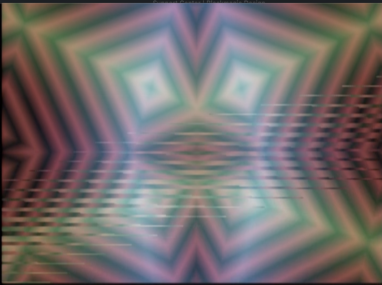


This is a known issue with V19 that will be corrected in V20 (coming soon!). Sorry for the trouble.
Good to hear! Thanks for the fast response!
I’ve never able to get anything going through the alpha or aux inputs on my MP. Does anyone have any tips? Generally working in Warp mode, and nothing I patch into those inputs seems to do anything. :-/
How these inputs work is conditional on the settings you have in the main menu page.
When the key mode is set to alpha it allows you to use an external key instead of luma or chroma keys.
The rest is in the Aux Mode, which controls alpha opacity, vertex mesh, or vertex spatial resolution. Patch some oscillators or ramps into aux and alpha and play around with those latter two modes, you’ll have a blast! Make sure to use the Aux slider.
when using the mesh stuff do yourself a favor and put some kind attenuation before the alpha input
I find it is so nice to use the AUX input and have control over the amount of the signal going to the effect
I use the bored brain splix so as to not tie up anything extra in the rack
koma cable these work too but I find the bored brain generally works better over more of the range of the slider
I’d be really interested in a firmware setting or hardware modification that would allow this. I can live with it but it would be nice to not have turbine sounds. 
I’m probably just not very good at searching - but where does it say what features are new in V19? Can’t seem to find that info anywhere.
The Memory Palace User Guide has a description of the current (V19) features.
When doing mesh stuff do yourself a favor and put a Doorway before the alpha input
Cool, thanks! Do you have any more MP tutorial videos in the pipeline, by any chance?
Yes, there will be a full module walk-through when V20 is released.
Woho, awesome! Thanks again.
I noticed the option for 5V scaling on the VC inputs seems to be gone on the latest firmware (I only see 0 to 1 and -1 to 1). Or am I missing it somewhere?
Also thank you @Genlok and @wednesdayayay for the alpha input tips! Finally wrapping my head around that action. Appreciate the help
any idea when v20 will descend from the heavens?
Soon! Have you tried the beta release?
Is the newest update “memory palace v2.0.1 beta”?
i have not, super tempting, how risky is it?
Zero risk if connecting via USB, slightly riskier if removing the MicroSD (but still low risk).
^yes that would be me damaging my MP by removing the MicroSD card! It was stuck and wouldn’t dislodge when I tried pushing/removing so I thought it was a ‘pull’ instead of locking. That damaged the locking mechanism. yeah so now my MP is sitting at LZX awaiting repair!! So might want to just try the USB route
i have a question about stills and the memory palace firmware.
will it ever be possible to use a parameter (e.g., aux or delay) to scroll through stills while in warp mode?
I think you’ll be pleasantly surprised with the upcoming firmware.
What’s the estimated eta on that?
can’t wait! beta working great btw!
I’m not sure if this has been brought up anywhere else before, but the X mirror is never centered on a 4:3 screen, even when using MP in 4:3 mode. Being able to offset this manually in the options would be handy.
Centering is definitely in the discussions.
My update experience:
I went for the SD card right away and wasn’t ware that the sdcard holder needs a push in of the card in order that it comes out again. I applied some force (not much) until I realized how it works.
The boot afterwards failed stuck on line “media ok” until I set the sync to internal and then on “frame 1 ok”. Pushing the red and yellow button lead to an SD card error. Pushing the boot SD button on the back lead to a black screen.
I pushed the sd card on the back in several times and appied some force in the direction of insertion on the little clip that holds it. Since then the Mempal boots normal again.
Please add some red cap note in the update manual about the sd card slot if others can confirm this issue!!! It might happen to others as well.
^You’ll notice my posting earlier where I damaged!! Still in the LZX shop awaiting repair. Just go the USB route honestly. I think it’s safer and don’t have to bother removing the module from your rig to access the microSD card.
Hey there, I noticed in my DJ stream this weekend, that y Symmtery is inverting not just the image but also the field dominance order too in some cases. So as seen here the lower y mirror still image has stair stepping the the upper does not.

Anyone else encounter this? Something that could be improved in future firmware I wonder?
https://www.twitch.tv/videos/705590424
In relation to symmetry, several others have already mentioned the Y being lower than middle of frame with Memory Palace. I also noticed X being off center, and generally have to fix it with a slight scale and reposition of 20-23 pixels. But the X off center seems to happen with all my various brands of synths and video mixers, so better not to change the X, but looking forward to the Y position update. =)
How’s the beta v2.0.1 coming along? I haven’t tried it yet waiting for official consumption.
The beta works great. You should try it out. Updating is very easy. Simply put the BIN file into either the SD or internal drive and select UPDATE FIRMWARE in the System menu.
Oh really? You don’t have to do the usual firmware update process involving a PC?
You will have to connect via USB or remove the MicroSD card to add the new BIN file to either the card or internal drive.
Updated to v2.0.1! USB route is the easiest and preferred here!
Is there an overview anywhere over what’s new in the beta firmware? I just loaded it up, but can’t immediately see anything different.
The Beta just fixes bugs present in V19. The upcoming firmware will have lots of new features.
Ah, ok, thanks! I still have a bit of a “jittery” image that I had on the last firmware as well when using the media loader as source - it’s like there’s an ever so slight movement going on with the aspect ratio or something. But I’ll try it out some more tonight, see if maybe there’s some setting I have on that’s causing it.
The beta definitely doesn’t solve all of the bugs in V19. Lars is investing a ton of time into V20 official to make sure there aren’t any future issues.
Sounds great - thanks for the info! Looking forward to it.
Hey folks. Just wondering something about the V19 firmware. In V18 when in the WARP mode, I was able to have the original keyed image stationary in the foreground with the feedback in the background that could be zoomed, moved, rotated, stretched as needed. I believe this was just a matter of selecting the routing of the keyer(?). Am I missing something, or has that option been removed from V19? If so, would be nice to have that feature back in a future update.
Also, incase it hasn’t been mentioned yet. In lieu of notched sliders to indicate the dead zone, it would be nice if the display noted when the slider was at the 0 position. Either with a value, or a colour, or other indicator.
Oh, and this was a suggestion that I made previously for the V19 firmware, but it doesn’t look it made the cut. It would be great to have option for what the rotation is relative to. The way I prefer the rotation orientation is so that when adjusting vertical or horizontal movement, the rotating object moves relative to the display, not relative to the rotated frame’s orientation. Does that make sense? In other words, if the object is rotating, adjusting the Y slider up will always move the object up no matter where the frame is in its rotation.
Thanks!
[Edit: I wrote all of that not realizing that a Beta v20 firmware was released eons ago. Apologies if any of the above was addressed in V20]
just another little possibly bug report
when in paint mode you can use the softness slider as a decay so that your paintings fade out.
this is awesome!
I’d love to see a bit more decay time possible. It seems like there is a tiny jump between not fading out and fading out pretty fast.
(using latest firmware)
however if reflect or tile are on then softness seems to stop working altogether.
Are there future plans to add in a snapshot feature from the ARGB inputs? I wouldn’t imagine it could do full frame rate sampling but I’d be very interested to see an extension of the animation looping where individual frames could be directly pulled into the Media Loader in Memory Palace.
You can already loop the most recent 64 frames of incoming RGB (using Freeze and A/B in any mode but Warp). To put that into the Media Loader, you’d have to capture your video output, split into frames, and load back into Memory Palace via the usual route (which is fun to do over and over again).
Yup, that’s roughly my current process for playing back animations with content generated within the LZX system. Just trying to save a few steps.
When you’re playing through frames on the media loader, it would be cool to have an option to add a fade transition between frames rather than being a hard cut.
Any hints on when we’ll see some updates to memory palace?
Any hints on when we’ll see some updates to memory palace?
Release of a bugfix update to clear some existing issues is in a WIP state right now (but being actively worked on.) We should see that in 2021.
I’m reserving Q1 2022 next year just to bring all the firmware to the same place, so that’s when we’d see Memory Palace integrate some of TBC2’s new code. From that point, we should have our development pipeline stabilized and be much more responsive across all products. This is the current plan.
Read from this post down for info on that:
To elaborate a bit:
I don’t have all of those answers for you right now. We haven’t reached any firm decisions on what will change about the Mk2 hardware, or when that change will happen. We have not done extensive testing of Memory Palace to determine it’s capability to run natively in any of the new Gen3 sync modes. Only that we need to make the revision before it goes back into production. Since Memory Palace is one of our main products, getting it back into production is a priority. So we’re planning for Q1 2022, which is probably the first we’d be able to tell you more.
Our main mission will be to ensure that firmware development will continue on Mk1 and Mk2 hardware platforms in parallel.
Whatever the case with hardware sync/processing modes capability – remember, your Gen3 system can always run in NTSC & PAL modes and be 100% compatible with anything before Gen3. So at a minimum, there is full backwards compatibility already planned.
this also makes me wonder how the Escher sketch will do with the new non ntsc/pal sync possibilities
this also makes me wonder how the Escher sketch will do with the new non ntsc/pal sync possibilities
Escher Sketch is much simpler, since there is no video rate outputs or inputs, it can run without sync.
What about using a passage or doorway with the gen 3 modules? Will those expedition modules be able to process Automata signals (oscillators, ramps) that are synced to HD rates?
If they don’t have a sync connection on the back, they’ll just work. Maybe some slight softening of the image but I’d imagine no where close to when using audio rate commands. HD is faster than SD but it’s much smaller jump than from audio rate to video rate signals.
Thank you very much for clarifying that. I had a feeling that might be the case. Hopefully the softness is minor and useable.
I really doubt you’ll get the extreme blur you might be envisioning but we’ll all see for certain when we get our hands on these new modules and start patching 'em up!
Yes, this update to Gen3 isn’t a huge bandwidth boost on the analog side or anything. We expect the Gen3 modules to perform a little better on the bandwidth side of things, but most of the update on the circuitry has to do with noise floor and signal integrity in general.
The sync timings are not hugely different from each other. The big resolution increase comes at the point of sampling or digital conversion. An HD signal is sampled with a 74.25MHz pixel clock instead of a 13.5MHz clock typically used for SD signals. So it’s the same analog signal either way. It just gets sampled more times, in HD mode.
So how soft some images get in the HD timings, I don’t know. It’s not the analogue path that’s fundamentally changing – it’s the way that path is being encoded and sampled.
As this topic is supposed to be about Memory Palace V19, I’m going to shut it down. Could y’all post further suggestions/requests for future firmware in this thread?
Questions about Gen3 Modules can go here:
LZX Gen3 Primer & FAQ: The Future With Chromagnon & LZX Modular
As we transition into a focus on our third generation of EuroRack video instrument products with Chromagnon, TBC2, ESG3, FKG3, SMX3, DSG3 and DWO3, we agreed it would be good to publish a primer about differences between what we are doing now and what we have done in the past. That’s the purpose of this post, to serve as a living reference and FAQ about anything related to compatibility, new options, or changes in approach.
Supported Video Formats
- Composite and S-Video inputs/outputs support these 2 timings: NTSC and PAL.
- Component (YPbPr/RGsB) and Sync inputs/outputs support these 15 timings: NTSC, PAL, 486p5994, 576p50, 720p50, 720p5994, 720p60, 1080i50, 1080i5994, 1080i60, 1080p2398, 1080p24, 1080p25, 1080p2997, 1080p30.
- In NTSC and PAL modes, full backwards compatibility is maintained with previous LZX modules and instruments.
- Most previous LZX modules and instruments will be able to integrate into a system running in HD timings.
- If the earlier module does not have a sync input or output, you can expect the module will function without additional consideration for video standards.
- If the earlier module has a sync input or output, it likely will not support the new standards, but will still work with the newer modules in their NTSC and PAL modes.
- There will be some exceptions to the two above statements, we’ll create and maintain a list of those modules along with additional notes.
Power Supply & Form Factor
- EuroRack form factor with maximum adaptability. Modules follow a consistent set of design constraints related to ergonomics, legibility of function, and mounting tolerances. All modules adhere to a maximum mounting depth of 45mm. You won’t be surprised by a future release that requires a case with more mounting depth, or find many off the shelf enclosure options that are unsuitable for LZX commands.
- EuroRack power supplies are optional, but not excluded. All modules may be powered directly from a 12V DC input barrel, just like industry standard video equipment from the Broadcast and CCTV industries. However, backwards compatibility is maintained with EuroRack power connectors.
- Low noise no matter the environment. Each module integrates a noise filtering internal power supply that keeps your signal path’s noise floor low whether the power input comes from a noisy 12V wall wart or a precision EuroRack power rail.
- Power budget expectations. DC 12V @ 25mA per HP. 3 Amps per 104HP is a good rule of thumb that leaves 15% headroom over this budget.
- The main things you need to know about power are:
- If you’re adding a few Gen3 modules to your combined EuroRack system or earlier LZX system, and your EuroRack supply can support the current, you don’t need any kind of special cable or adapter. Just install the Gen3 module as you have Orion, Expedition and Visionary commands.
- If you’re starting fresh with a Gen3 system, we recommend you skip EuroRack power entirely and power your system with a 12VDC distribution module, bus, or cabling. Combining a passive EuroRack enclosure with our DC Distro module is a good place to start.
The Story So Far
- In 2019 we reached the decision that we needed to make an architectural shift in the design of our products. We needed to solve for some performance issues introduced by the variable nature of EuroRack power, and create a better power ecosystem for video processing in EuroRack format. We also wanted to make sure we were fully implementing the capabilities of the hardware and format, by introducing a range of new supported video standard timings. Furthermore, we wanted to standardize all of our circuitry to a common library of hierarchical schematic blocks, make some tweaks to our ergonomic standards, and really create a canonical set of core modules we could commit ourselves to in the long term. In other words: we had stuff to change – and it was better if we could do a complete redesign.
- Throughout the end of that year, we discontinued most of our catalog of modules and began work on Chromagnon, which is meant to be an ark project that allows us to restandardize all the main components of our core circuitry in a single project. Chromagnon is a master design reference for anything to follow (we solve video input, output, tbc, ramp generators, and core analogue circuitry in a single project.) We also swept TBC2, an existing Orion project, into this initiative so that we could ensure we weren’t releasing two TBC type modules back to back with different feature sets.
- We opened preorders for Chromagnon in early 2020, expecting we could be shipping the complete instrument in full by that Summer. The pandemic forced us to close for a few months right as we were, as a whole team, highly focused on getting that job done. The months of uncertainty that year and isolation from each other pushed our entire schedule into chaos.
- In 2021, we were finally able to begin production on Chromagnon. During this year, we built over 700 control board assemblies – while these assemblies represent the bulk of the assembly hours required to build a Chromagnon and most of it’s material costs, they are all still waiting on completion of the rear assembly before we can turn them into complete instruments. TBC2 & The Chromagnon rear assemblies are closely linked to each other and firmware development has been slow going. But as we near the end of Summer 2021 we have solved most of our issues with both projects, and have all essential features working, but were about to get distracted.
- In late 2021 our production team ran out of work, and had taken the Chromagnon assemblies as far as they could go up to that point. Since we had discontinued our previous catalog of products this left us without a product to build, since Chromagnon presales were dwindling and we had no other primary product available for sale. Chromagnon rear board finalization was going well, but we were experiencing setbacks, and new problems – supply chains for our most expensive subcomponent, the Zynq SoC, were becoming more expensive and uncertain. We needed to revise the boards again to take this into consideration – that way we’d have multiple strategies on the path to fulfillment.
- Running out of revenue in late 2021, we decided that we needed to release the first few modules of our new core modular system, and that we needed to engineer their internal sub-assemblies to also be reusable in the final Chromagnon host assembly, this way we are taking two steps forward at once: One toward Chromagnon fulfillment and one toward having a modular video synthesizer system in stock again. It would mean another overall slowdown in the schedule, but at least we would be moving forward on firm ground.
- Coming into early 2022, this plan has worked out well, and is allowing us to continue our work through your support of the new module releases. We’re focused right now on delivering on the long term projects most (TBC2 and Chromagnon), as well as introducing our new 5-module modular system into production to support us while we do that. After meeting these deliverables with TBC2 and Chromagnon, we plan to spend a while patching these new instruments, promoting them, and catching up on educational assets and documentation related to them.
Circuit Designer Notes
- The Gen3 circuitry is built on the Patchable Video Standard.
- All analogue functions are on 6-layer PCBs with dedicated internal planes for power and ground connections. We found this was one of the most effective methods we have for improving overall performance of the system.
- Texas Instruments LMH1980 is used exclusively to extract timing from sync inputs, using the recommended application circuit in TI’s datasheet.
- All video and sync output jacks are buffered by video opamps and intended to drive a standard 75 ohm video transmission line. There are no 75R termination / loop through options to ensure the transmission line is not hindered by electromechanical contacts in switches. All outputs must be buffered.
- To minimize stackup of propagation delay along a series of rebuffered sync outputs, place modules with lower timing requirements towards the end of your sync chain, or use a video distribution amplifier to distribute sync from your source generator in parallel to all commands. We don’t expect this to be a practical concern for most users.
- Our local analog power supply for most modules uses +/-5V power rails, generated from internal switching DC converters and ultra-low noise low dropout regulators (such as Texas Instruments TPS7A4701 and TPS7A3301). Power supplies for digital parts such as systems-on-module and FPGA subsystems are typically derived directly from the 12V power entry with separate power supplies designed for their needs.
[UNDER CONSTRUCTION: Additional sections will be added to this document over time, as relevant – please feel free to discuss or add questions below]
Thread Replies
Does this mean we need to use a 75R terminator for the end of a sync chain?
Not quite, it just means every sync input is already terminated, and all sync outputs are buffered transmission lines. No 75R switches or loop thru option. This allows for a much more consistent expectation in terms of sync distribution and performance, and is most reflective of how modern broadcast gear works when dealing with sync references.
There is a 10ns propagation delay per buffer, so at worst, that means that if you have your TBC2 downstream from your ESG3 through a few buffers, you’ll have to adjust the pixel delay on TBC2 to get pixel-perfect alignment relative to output sync. So this is what I mean by “not a practical concern for most users.”
Ah, got it. Thanks. I figured I was misinterpreting it.
3A per 104HP? Wow, no wonder y’all moved to 12VDC and onboard power. That’s fully bonkers. The step up to HD bandwidth requires that much more overhead?
How does the onboard power compare to say a linear supply?
Here I was expecting to power my system over euro for ultra low noise but sounds like even a 25A supply might be getting close to the power budget 
Looking at the total load, it’s not too far from our previous recommendation of 20mA per HP (10mA per HP on +12V and 10mA per HP on -12V.) It’s just all on one bulk rail. It sounds like a lot until you realize you can get 3Amps of 12VDC on a wall wart for much cheaper than any EuroRack options available. Just look for power supplies designed for CCTV equipment and LED lighting.
There’s also a lot more circuitry behind the panels of these new modules compared to anything we’ve done before. These are new, all-discrete circuit design topologies, which run a little bit hotter than some of the ASIC parts we’ve used in the past like LT1256.
None of this really relates to HD vs SD bandwidths specifically – it’s more about improving the performance of the environment all these signals live inside across the board.
How does the onboard power compare to say a linear supply?
Typical ripple in a linear supply is 3-4mV. Our power board’s noise floor is < 1 mV ripple. It’s analogue, so I’m sure there will always be some noise beyond that to contend with, especially if you’ve got lots of gain stages in your patch. But this is far and beyond cleaner than what we’ve done before.
Here I was expecting to power my system over euro for ultra low noise but sounds like even a 25A supply might be getting close to the power budget
Yeah no need for that – that’s part of the point – you don’t need to speed hundreds of bucks on low noise EuroRack power supplies or busboards – because on these modules you’ve already paid for that (they’re integrated into the power entry, and part of the module’s price tag.)
If you’ve got existing power solutions for your earlier modules that are working out great for ya then just stick to those! No need to change anything. You can squeeze a couple Gen3 modules in if you want. But if you’re planning a whole Gen3 row, just skip the Euro power supply and power it from the bulk DC12V instead.
By my rough calculations, that’s around 2A per 84hp row. A 12U rack cabinet gives me 4 rows, and require maybe 8A of power.
So my plan is to a pair of DC Distros to power a 12U cabinet for my Gen3 commands. Anything standalone, like Chromagnon, can sit outside the cab. I have an existing 12U cabinet using a pair of Malekko PSUs for older commands.
I love Gen3. It solves all the power issues that have been bugging me since 2015. Thanks!
Hadn’t considered that it’s all on the bulk rail - that’s more promising for a DIY clean power scheme - was thinking 3A± per 104.
I’m in the camp of having gone through the massive pain & expense of building/designing a clean power solution for my setup so was just trying to wrap my head around if/how that fits into Gen3 going forward.
Thats really impressive that they’re sub-1mv, brilliant move by you cats for building an onboard power solution - too long has power been the bane of video modular. Hell, eurorack in general, but video especially.
RE the dc distro
is the preferred use case that each output gets its own module or will it be ok to daisy chain multiple modules together?
iirc from the original spec for it, you should be able to daisy chain multiple modules together
hopefully this will also work with just putting a hole in the case and daisy chaining a 3A (or more) 12V power supply…
We won’t officially be supporting any daisy chain cables just because it’s a potential liability. You do not want to have loose/disconnected hanging DC barrels crammed behind the modules in your rack after installation – that could short against parts or connectors on the rear circuit boards and cause issues. So if you have unused connectors on your daisy chain cable, be sure you cap them with an insulated barrier or insulate them with electrical tape, etc before power up.
Also, with daisy chaining it would be possible to connect more modules than your power barrel/brick can support. So it puts you in the position of adding up your current ratings. On the LZX DC Distro the connector itself is rated for 5A maximum. So even if you had a 15A brick for example, you wouldn’t want to push 15A of current through the connector.
Also, if you are going to daisy chain you need to ensure you are using a wire gauge thick enough to carry the current. So you’d want to do it in segments, not in one long row. For example a 1 in, 5 out chain cable per row, with each cable going to a DC distro outlet, would be better than several daisy chain cables in series with each other.
TLDR; Daisy chain is okay, but you need to know what you’re doing. If you stick with DC distro or a limited scheme, you don’t have to think about it as much.
I prefer parallel distribution like DC Distro or these kind of supplies, where you have parallel output adapter from the power brick directly:
this looks to be the same thing but for uk!
Yes, you shouldn’t have trouble finding a wide variety of DC12V solutions! There are CCTV supplies designed to be used with pigtail leads as well, and rackmounted options. Also any generic 12V switcher closed frame supplies like from Meanwell, etc – or DIN rail mount bulk 12V supplies, are all options if you want a dedicated install without wall warts.
I’m sure some of these 12VDC parts are better than others (connector/cable quality, power output stability, expected lifetime of use, etc) but the great thing about any of them is that they are all easy to replace or maintain if something burns out – and most importantly, the Gen3 modules should perform consistently regardless.
Anything we stock at LZX will have to be marked up over what you’d get on the open market, but I view that more as the cost of a verifiable supply chain – if we’re offering something like DC Distro, DC jumpers, power bricks, etc it will be after we’ve put in the work to test them with the system and ensure that a user with no desire to learn the ins and outs of DIY power options can just plug it all in and it works.
For the DC Distro, that’s the “this will work, I don’t have to add anything up” approach. If you start daisy chaining, just make sure to add up all your module currents and make sure it does not exceed either 5A (the connector rating) or the DC brick rating. (And insulate any unused output connectors!)
There will be some revised DC distro options coming as well as barebones rack ear + rail kits. The current plan is to have those ready at the time DWO3 is put up for sale (the last of the 5 module basic modular set we’ve been working on.)
That’s why I plan to use a selection of 2-waym/3-way splitter cables with my DC Distro, with the splitters “upgrading” as I add more modules, up to a max of 14 modules on one brick (using up to four 3-way splitters and a single 2-way splitter).
That sounds like a good plan. Little velcro straps to keep things tidy as you go is probably a good investment. Due to the L shape of the gen3 modules, there’s a kind of cavity created just below the DC barrel connectors on the rear, the intention is that even if you have a shallow case, this pocket area is enough room to keep any rear cables neatly wrapped rather than potentially smashed against the back of the case.
If you are adapting an existing case and want a no-soldering easy install (and don’t want a DC power entry module up front) you could use a DC feed thru bulkhead, like this:
Well, I’m using 19" racks with an 8" depth. I think that should be deep enough for Gen3!
I like the cable-tie tip. I have some simple “wire” cable-ties that came with various cables, so I coudl make use of them in my Gen3 case. However, I shall now also consider using velcro. Thanks.
I’ve just got this one. The output jack from the PSU isn’t 2.1mm. The adapter has 2.1mm outputs but isn’t suitable for bulkhead mounting. Just something to keep an eye out for.
Edit: the other thing that I’m seeing is a lot of adapters with a 2.5mm internal that are being advertised as 2.1mm. They only show the dimensions on a small diagram and claim that they are compatible.
Thanks for this update. When reading the explanation of how things went with Chromagnon and TBC2 it definetely makes sense
And it’s good to know that my earlier investment in a huge power supply wasn’t for nothing…
Have to read this more later, but wanted to say I am super excited about 1080p, and 720p 60fps in particular. Progressive and High frame rates are gonna be awesome for sensory translator work. 
Oh, yes. For me it would be 1080p and 50fps PAL. I have a lovely set of PAL CCTV cameras that I use for feedback. I also have some HD-SDI dome cameras. So I’m real interesting in how all these might work in a hybrid SD/HD feedback setup. I also have a pair of Sensory Translators begging to be used in this context. Nevermind processing HD video and stereo audio.
Ah man - I hate to be the one to bring it up - but the mention of TBC2 being interrelated/co-dependent on Chromagnon. Should we still expect to see TBC2 right after the rebuild is done on this first batch (I believe there was a post in December saying around something like around 2 months for rebuild?) - or is it going to continue to be held back as Chromagnon testing & finalization continues? Theres nothing I need more than to inject some external video into my system. I just ordered my third Composite to component converter for Visual Cortex - both had scaling options but nothing locked, gave me any image. Fingers crossed for #3 I guess, it was the expensive one
TBC2 rebuild is in progress. No setbacks from Gen3. The team continues to push hard to meet goals.
Hey, in case you haven’t come across this yet, the Ambrey composite to component converter is most people’s go-to for this as it definitely works with Visual Cortex. I know how maddening it is to try to solve this issue, so here’s a link:
Firmware is looking great on all of these projects, it’s the hardware being finalized that’s holding us back at the moment. We can’t release any firmware until the hardware is 100%, so that’s where we’re focused.
Remember that TBC2, Chromagnon, and anything with sync or ramps infrastructure in Gen3 (ESG3, DSG3, etc) all share a common codebase. It’s going to be to everyone’s advantage that we did it this way (it’s important that we are testing all of them together – TBC2/Chromagnon/ESG3/DSG3) before releasing any of them, but it’s been a long haul to say the least.
To put it another way – ESG3 or DSG3 being done also means a huge chunk of Chromagnon/TBC2 is done as well. Everything’s moving forward together. The modules have actually been helping immensely with finally conquering the big projects.
Ah man - I hate to be the one to bring it up - but the mention of TBC2 being interrelated/co-dependent on Chromagnon. Should we still expect to see TBC2 right after the rebuild is done on this first batch (I believe there was a post in December saying around something like around 2 months for rebuild?)
It’s a perfectly valid question. Yes, we will ship TBC2 as soon as the rebuild is done (meaning within 2-3 weeks of the last of the rebuilt units being completed and fully past testing). The rebuild takes priority over all the Gen3 modular projects. The past month we’ve been pushing through the modular projects hard so that we have some coasting momentum in order to power thru TBC2 fulfillment.
We’ve had some detours, as I’ve tried to explain – at the intent of every decision we’ve made has been “what gets TBC2 and Chromagnon done?” ahead of all else. Unfortunately that’s involved “we have to release these modules so the company doesn’t die” over the past several months. If the company dies, that just leaves me alone to try to fulfill on TBC2 and Chromagnon, possibly on top of a dayjob, and that is just not realistic. So it’s a 2 steps forward, 1 step back scenario.
Every day we get closer, and right now the team is optimistic and working at our best.
Here’s a shot of the whole family under test from last week.

Thanks - Good to know, that is the one I just ordered! Saved the best for last haha Unfortunately 3-4 weeks in between each order for international shipping to test so its been quite a long saga
Great, you’ll love it! That little Ambrey box is surprisingly valuable; for some reason VC won’t sync to my V40HD when fed component signal, but putting an Ambrey converter between the composite out and VC works like a charm, which has been necessary to get mixed HD video sources into my rack. Hopefully TBC2 will solve all this, but still the Ambrey box just works, and that’s what we all want 
Thanks for sharing the link! I bought one for this price years ago when I first snatched up a VC, but I’ve noticed the price is a little high from the one guy I see selling it on eBay. Definitely worth it.
Hey Everyone!
Just curious if I missed a wave of shipments. I ordered a Chromagnon some time ago. Did I miss anything or are we all still waiting? I asking because my mailing address has changed three times over the years…
Thanks
Ofield
We’re all waiting, it has not shipped. Project timeline is on LZX’s website: https://lzxindustries.net/products/standalone_devices/chromagnon
You can email LZX to update your address.
Which other modules functionality overlaps with Chromagnon’s? Are there any modules that Chromagnon makes redundant entirely? I preordered a Chromagnon as my starter module, and am looking at modules to see what might go well with it.
Each additional module adds to the potential of additional complexity and control. I can’t really think of a module that would be redundant alongside Chromagnon. Maybe there are modules you wouldn’t find as useful, but that depends on what you are trying to achieve.
If you are interested in shape generation, then adding DWO3, DSG3, and modules to treat and combine their outputs would be best. From a pattern-making chain of modules you can then use Chromagnon to further complexify and animate the results for final output.
If you are interested in processing external video, you will want good modulation sources. DWO3 is also handy in this iteration, as well as Proc, SMX3, and modulators like LFOs and envelope followers.
Most LZX modules do double duty in external image and shape processing. There isn’t necessarily a wrong choice.
What about the video I/O modules TBC2 and ESG3?
TBC2 adds extra video inputs (plus other features) and ESG3 adds an output with brightness and contrast knobs (and invert/mute switches). Both would be useful expansions (or alternatives) to Chromagnon’s i/o. Not redundant, but it depends on your process and whether you need or could use expanded i/o.
Welcome to the forum @parallaxCloud
Basically Chromagnon replaces 5 (maybe even 6) Expedition modules, the range before Gen3. I’d say the list is: ShapeChanger, Navigator, Staircase, Mapper, Cyclops. (update: I forgot about Polar Fringe)
The only obvious one-to-one module in the Gen3 range to the list above is Stairs & Staircase but as @Z0NK0UT pointed out, there’s nothing wrong with duplicating some functions and Stairs/Staircase are really powerful, instant satisfaction commands.
Stairs doubles the number of outputs of Staircase, from 3 to 6, and triples it’s inputs although the 3 are summed and then processed together but hey, it’s a 3 input summing mixer thrown in which doesn’t only have to be for an RGB signal from a TBC for instance.
Someone fed back one of the outputs of Stairs back into one of it’s inputs and hey presto, Stairs owners suddenly had an instant snow-crash noise module in their racks
Although there’s currently 15 Gen3 modules currently available, many of those coming soon & next year will be function blocks of Chromagnon’s functions regarding movement/rotation, I’m sure many others won’t and yet all will be good additions to a Chromagnon centered system, imho.
Without knowing the signal routing in detail (ie, understanding if each section be patched individually) I wouldn’t so much say the Chromagnon “replaces” specific modules as much as “performs similar functionality”…
did youall do the knobacon thing yet? and if so do you have any video footage of the event we can watch.?
Knobcon Number Eleven, runs September 8-10, 2023
You’re right @Rik_bS but I was sure I basing what I wrote on something I read on here. I guess it’s an interpretation of this:
Discontinued:
Polar Fringe (replaced by Chromagnon)
Visual Cortex (replaced by Chromagnon, and other future Automata instruments)
Navigator (replaced by Chromagnon)
Shapechanger (replaced by Chromagnon, and other future Automata instruments)
Cyclops (replaced by Chromagnon)
It’s part of an older but important post. It’s towards the bottom, under “Discontinued”.
Here’s the link:
Any update on gen3 LFO & envelope follower modules? Pendulum I use all the time, been wondering what will replace it.
I suspect a new envelope follower is low on LZX’s list considering VH.S just dropped this bad boy: Aural Scan Video Synth — videoheadroom.systems
DWO3 is pretty impressive for LFO duties, so we have been leaning on that. And the Video Headroom Systems Baja feels indispensable. VH.S also has an envelope follower coming out, as @Vdot mentioned. There are LZX designs for these functions on deck, but we don’t have a timeline laid out.
DWO3 is a great LFO.
Syntonie Animate + Expander also looks amazeballs.
+1 on the Syntonie Animate & Expander combo although the Animate will go a long way too.
A Square output can be sent to a clockdivider to get fractions of the tempo/LFO speed too.
We have new voltage source modules in development. Lfo has been talked a lot. And gone through some very different at times panel concepts. Something more video rate will be happening first. Things that have been mentioned include easing curves. Phase relations. Timeline™️ vibes.
As far as lfo. Yea. It’s kinda like this.
Dwo. Benefits from static cv offset input for very slow stuff. Gives you all that video rate rizz. (Also hard to sacrifice a video rate to do lfo mode)
Syntonie. Gets you lfo only at price reduction from dwo. Ample waves and more with expander. Listed range is 100 seconds. Not sure if you can cv a higher voltage than 1v (normalled to cv input) for extra low low. 4 phases
Baja. Goes slowest with or without patching. Smallest footprint. Single waveform. 6 phases. Ribbon pwr only
I keep putting off Bajas because early simple translations to 5v weren’t instant success
Ease curves, phase, great things to consider. We do have good options in the audio realm, it’s just the voltage conversions that get in the way. Ornament and Crime Plus meets most of my needs, if I can just get the tuning right. If I can get a really precise 1-5V sawtooth into OCP > Hemispheres > VectorMorph, I can map that onto any function curve and phase. I imagine the newer, sexier versions of Disting would also go quite a ways down that path as well.
Anyway, it would be epic if some app-based digital CV magic made its way to the native LZX voltage standard. Custom function curves would effectively enable simple timeline operations, i.e. random access value mappings. (OCP Hemispheres does this) Add a CV digital delay line or two, and Bob’s your uncle. (Disting does this)
DWO is great, I don’t see it as sacrificing video rate to do LFO. I see it as a versatile option that saves rack space. Driving the FM input into negativland gives me all the slow LFO range I need.
any digital module with open source firmware - all mutable instrument except beads, and a lot of others, o&c - should be reasonably easy be update to use 0-1v instead of 5v…
mutable ones that I can think of that would be useful for video - ie mostly modulation would be tides (both versions), frames, peaks and stages
doesn’t really need huge amounts of coding skill either… just work out where the output values are being sent to the pins and adjust… and build and reflash… probably a bit hit and miss, at least to start with though…
… for someone with considerable relevant skill and experience
Changing the scale should be a trivial programming task. Greater changes have been made to the firmware for Mutable Instruments commands. As for updating, see the update instructions for the Parasites firmware.
However, I sold all my digital MI modules and I no longer have any space in the one cabinet in which I could cleanly power them.
I now use a pair of Sensory Translators as my “programmable” modulation sources. I feed them with sine waves with varying amplitudes, generated using CSound, tuned to the frequences of the Sensory Translator bands.
So much easier for me to program and update. I’m sure the technique could be adapted for Aural Scan and other sine wave sources.
indeed - the relevant skills: reading, maths, following instructions and a willingness to spend some time and effort…
no experience necessary…
it’s not like you need to become a fully fledged C++ programmer to do this… and once you’ve done one the others are more than likely exactly the same…
What’s the advantage of this vs. simply generating control voltages and outputting via a DC coupled audio interface?
I have no modules that can produce such complex signals. I usually want slowly flucturating CVs. While Marbles can generate 4 of them, it’s 18hp wide. That’s a lot of panel space for only 4 useful CVs! So I use a pair of Sensory Translators to get 10 fluctuating values. I can also generate any other complex signals, and they can change at any time. Even better, I can sync them with a video signal to get 3 video-rate CVs. I generate the video signals using FFmpeg, of course.
I’m now starting to experiment with more complex audio/visual generative techniques, This is done by writing code that generates filtergraph and/or command files (via the sendcmd filter) for FFmpeg, and score files for Csound. I’m also writing code to generatively edit the video in post-production. I may someday write more code to generate audio synched with the video.
Various examples of these techniques may be found via my Vimeo account.
I’m just saying, if you are good with Csound or whatever, something like Expert Sleepers ES-9 is a much more direct approach. Your use of fine-tuned sine waves through dual 5-band envelope followers is a clever approach. But you can easily just generate the control voltages directly. ES-9 is not cheap, and it “only” has eight outputs, but it is cheaper than 2x Sensory Translators, and I think it’s overall a better solution. I’m planning to go down that road eventually.
I have several problems with Expert Systems commands.
The first is that they’re not class-compliaqnt. Even using Windows 10, the driver didn’t work.
The second problem is that I don’t have space for a computer in or near my video rig. I might be able to set up a Rasperry Pi running Debian and Csound, but that would require a class-compliant soundcard.
So I use a pair of LZX modules instead. You can probably guess which video player I use to provide the audio and video.
Sorry this is drifting super far off topic. I’ve not had an issue with the driver for my ES-9 on Windows 10.
If you’re not using a computer, I don’t understand how you’re using Csound.
I use a computer running Ubuntu in another room. I use to create or prepare videos I can play into my video synth. The last time I used a computer and the synth in the same room was 2015.
You’re right, this is drifting off-topic. I was simply responding to Agawell’s post about custom MI firmware by describing how I avoided that. I’ve done that and said more than enough now.
#O&C
Ornnament & Crime at 1V

Your settings may vary.
It depends a bit on each unit and their calibration.
That said, setting o&c to 1v is fantastic, I used it a lot before having the syntonie lfos.
Having weird waveforms in audio range oscillators and feeding them to diver is a simple and nice patch.
Interesting to read about Ornament and Crime’s 1v capabilities. I’ve got Zadar, and while it has some wild waveforms which can be skewed in interesting ways, it doesn’t sync to video rates from what I’ve tried so far.
What can take sync (my system is Visual Cortex-based) is Vermona’s uniCYCLE, and it’s already a lower peak-to-peak waveform at 5v instead of 10v like most audio euro oscillators. I can get it to do multiple horizontal lines, but only one vertical line will sync, effectively becoming a ramp. Fun to modulate its even waveform’s pulse width when it’s moonlighting as a horizontal ramp! (I asked and Vermona did not intend them for video use, thus hasn’t mentioned it in their materials, but they’re more versatile in practice if you’ve got an interest in both A & V.
Regardless, it’ll be some time before I’ve caught up with the Gen3 commands. I’m excited to see what will come next, and hope to see more “3 Patches” videos if they’re still making them.
I am curious to know what the downresing/upresing experience is with Chromagnon. Synthonie video delay/enhancer modules have caught my eye. Can Chromagnon output to these modules via composite video, then upres the resulting composite video back to 1080 60?
Seems like I would need another output module to export to the synthonie modules, then pass the result to Chromagnon for upresing.
I use the Hemispheres firmware for O&C, it’s like having two complete modules in one. And the Plum Audio version, O&C Plus, adds some indispensible options such as attenuverters, and the all-important +/-5V global switch.
I’ve done the 0-1V dance with OCP plenty of times; one of the apps is Attenuate / Offset. But that uses up one of the hemispheres. I’d rather use both Hemispheres for creative apps. Best to send the 0-5V outputs through a Cadet V scaler or a BSO 5:1… except, as I have lamented many times, the former requires DIY abilities and free time, and the latter is no longer in production.
Chromagnon can upscale or downscale, but only exactly once. It’s a single channel device. You can’t send CVBS out of Chromagnon, through some other boxes, back to Chromagnon, upscale, and output again.
So you probably need a TBC2 if you want to integrate those Syntonie glitch modules in an HD workflow. Or you could do everything in SD and upscale at the end of the chain, either with an HD upscaling device or in software.
Scopic Modular has a 2hp down-scaler available as well
Very cool. Any recommendations for lightweight upresing? Are there light weight modules for going to/from CompositeVideo and Component Video?
Oh yeah! I forgot about that. Thanks! A five to one voltage converter that’s actually in production! And only 2HP.
Not that I know of… it’s pretty involved from a technical standpoint. Either a full digital frame store, or an intricate analog scan conversion. Many HD mixers will automatically upscale to their chosen output format. There are also numerous legacy standalone scaler boxes from Extron and other manufacturers. And if you’re just recording, not doing live performance, you can always upscale in post using Premiere or whatever.
Hi! I have a vessel case with 2x capsule power. If I want to put some gen3 modules in this case can I power them via a daisy chain from the dc socket on the back of capsule power module(s).
I powered the system on and plugged a dc power cable into the capsule on the right side of the case and measured 11.95V on that connector with a multimeter so it seems good to go. I am using the 8.34A supply that came with the case.
If I put about 10 x gen3 modules in 2 chains of 5x modules daisy chained from each capsule on 1-5 fx pedal daisy chains, the load would be about 1A +12V on each chain . and for the remaining modules load will be approx. 575 mA +12V | 340 mA -12V on each capsule . thanks!
The combination of Capsule and barrel power in that case will make it very flexible for building a system. You can definitely plug a splitter into the DC outlet inside the case and power some Gen3 commands.
oh great, thanks chad !
Hello friends,
Have I missed any important updates in terms of Chromagnon shipments?
Thanks in advance. I suppose I can hunt down the most current schedule.
b4_H
We have been preparing an update, but have not yet sent out the newsletter. Soon!
Is there a list somewhere of the expedition modules with sync connections that will work at HD rate?
See also:
I have a question about the distant future, long after the Chromagnon saga.
I vaguely remember something about Automata instruments, specifically a texture voice. That and a line of new DIY commands. Are there any vague plans in those areas still?
I don’t know about Automata instruments for future release, but I recall that being talked about in the past too.
As for DIY, this module is currently available in built and kit form and seems to be a solid step into the future of DIY modules:
Oops, I hadn’t read the latest blog post. So the P Series [like the PGO] is the foretold DIY successor to the Cadet series. That’s awesome news!
Good Day,
For the record- Chromagnon has NOT shipped right? I’ve moved twice since I Bought it however many years now. 4-5 I take it. It’s hard to keep up. Thanks
LZX Status Update 6/25/2022
It has been a busy Summer for us here at LZX, with both R&D and our in house workshop! Here’s the state of all current projects at the end of this past week.
-
During the last half of Q2, ESG3, DSG3, and TBC2 hardware units have been assembled, but waiting for a production firmware release before shipping begins. We finished those releases this past week, and all three modules are now being beta tested in house with release candidate firmware. If everything continues to look good, we’ll start shipping in July. This is a final testing phase for the firmware/hardware (after many before it), so we expect it will go smoothly.
-
DWO3 needed another PCB revision after the one we thought was production ready. We have revised some performance critical components of the design that will have been well worth it in the end. We will be entering production on this module in July if our first articles of this next revision look OK.
-
With these projects out of the way in R&D, we can finish finalizing the Chromagnon hardware/firmware. We have built our way to this point carefully, redesigning a large portion of the device around the use of a subassembly that will help us navigate the current electronics supply chain with less risk – it’s been more time up front, but makes the final part of the job, and the transition into operations/production/fulfillment go much more smoothly. So expect to see some news about the Chromagnon hardware next from the R&D team, in August.
-
There are 5 new utility modules ready for Gen3 that the workshop got moving during their wait for ESG3/DSG3/TBC2 firmware releases, and we will have initial quantities of these modules available for sale this week. The modules are Sum/Dist, Proc, Matte, Keychain & Stairs. We won’t be accepting preorders or backorders on these new modules, so when you seem them up for sale, it will be after the listed inventory count is boxed and ready to ship. So there may be some availability gaps due to our need to prioritize preordered products, but that should only be temporary while preorders are being fulfilled.
We’re nearing the end of a very long journey with R&D since 2018. On a personal level I’m excited to focus on wrapping up some loose end firmware projects, writing more user docs, and getting back in touch with the community.
Please let me know if you have any questions, and thank you for continuing to support us no matter the weather.
Best,
Lars & Team
Workshop photos from the past few weeks:


Thread Replies
hell yea. are there going to be any demo videos of the upcoming smaller modules?
We’ll be sending those along with ESG3, DSG3, TBC2 to Johnny Woods very soon, to do more 3 patches videos. It’s going to be hard to allocate a lot of time for demo production in house until the Chromagnon release, but we could do some live Q&A/patch streams that get archived. I will try to at least post some patch diagrams.
This is such great news @creatorlars, thanks for posting it 
& someone’s already posted it to Discord where its creating an active conversation too.
Nick’s stream today was great yet I only caught the last 75 minutes or so. He did a quick Stairs & Staircase A/B (upon request which was damn nice of him considering he’d probably already done it earlier in the stream) & jez, what a difference! Gen3 is the bomb!!! Congrats 
Thanks for the update! I’m happy to see you all completing your multi-year vision and am looking forward to… well, all of this!
Where does the big firmware update (Mem Palace, Diver, etc.) lie on the timeline?
I’m so interested in purchasing these first 3 commands. However, I have not done any pre order yet. So does that I’m out of luck on preorders being all filled and essentially I cannot order any units till q4? Or is the July run of shipments going to have a reserve of units that can still be purchased today???
Thanks so much!
-d
It might be worthwhile finding an LZX dealer near you, and enquiring if they have anything on pre-order that you could purchase.
Or maybe just wait until product is made and distributed then hunt down what is available in the market… less ambiguity with that approach.
TBC2 might not reach ready-to-ship inventory until Q4, but ESG3 and DSG3 should be in stock sometime this summer. I fully expect all three modules to be available somewhere online shortly after they begin shipping–either from private parties or dealers.
Definitely excited about a Staicase type module in Gen 3 
Out of curiosity what is the price point going to be for these 5 new utility modules that you’re hoping to put up for sale this week?
Prices will be announced when the modules go up for sale this week.

That was a nice surprise to pop up

What is the Keychain module?

KeyChain is 3 hard Keyers. Nick gave a cool demo of its style of output on the LZX Twitch account about a month ago but its not up there anymore. He used the Visionary TFKG module on a camera feed & it looked great!
Hey Pascal @meudiademorte, was it you who posted a link in the Discord recently to a Google Drive backup of some or all of the previous Twitch streams that Nick has done?
Here’s the said link:
https://drive.google.com/drive/folders/16qsDG_v0OFGjhVoBNDxUiAmLb_q20qhf
Yws, i did a back up. Have to upload the last 2.
Thank you for this. I missed several due to a fluctuating work schedule and was bummed to think they were gone forever!
Happy to say that I’ve released a production version of the ESG3 firmware today, after spending the past week tuning the genlock input timings.
I should be able to say the same on DSG3 within the next few days.
I gave a video synth workshop here in Berlin this evening, Sunday 10th July, & it was nice to tell a couple of the participants, who pointed out that the Visual Cortex isn’t even on the Schneidersladen page anymore, with full confidence that ESG3 is imminent and the wait for an encoder is soon over.
It’s been a bit of a long week for us here – initial batch testing of 9 units of ESG3 on Monday uncovered a new clock crystal tolerance related issue. A couple units were outside the other unit’s lock ranges at their resting frequencies. We’ve got this resolved now it appears – but we are going to be testing for another day or two to be sure, before we can say we are done. Some of us are also out of office or sick right now, so I don’t think there will be any ESG3 going out this or next week.
Right now, it’s still looking likely we’ll be at a spot where we can start shipping them before the end of the month.
This week, we also added a test pattern generator mode to TBC2, so that we can have a native reference for 1V color bars. This is making the RGB calibration on ESG3 units very pleasant, as you can see from the below photo. We pulled out a Tek WFM90 vectorscope we’ve had lying around for ages, and are putting it to work.

TBC2 firmware has been performing great, but I’m trying to get ESG3 out the door first (so that I have an output to evaluate TBC2 with other than Visual Cortex.) It was nice to see how quickly I could add the extra generator mode to the software engine, which bodes well for the speed at which we’ll be able to release new firmware extensions post-release.
dang, never seen a portable vectorscope like that before. cool stuff!
color bars end up being such a fun input to the video synth
glad to see it built in! otherwise it would have just ended up a still on our TBC2
hopefully some more people will take the time to really get to know chroma key on the memory palace with these bars
Yes, test patterns are great. I have a Kramer VGA downscaler that generates a test pattern when there’s no VGA input. As I usually have no VGA sources, I use it mainly as a pattern generator. It’s great when I need a complex pattern and I’ve run out of modules to patch something up - or I’m just feeling lazy.
Yes, especially if we are just rendering a still frame, it’s easy to have all kinds of software generators in TBC2. Here is the basic RGB ramps generator. All of this will get ported back to Memory Palace at some point.

I think a development diary approach tends to work well for that! So I am going to try to keep this thread updated weekly and at any eventful milestones.
Forget if this has been shared before, but if anyone needs some down-and-dirty color bars (for fun stuff), a ramp + Castle ADC works great.


Output:

Just a technical note: That technique works well for 100% color bars, but most vector scopes will expect 75% levels (0.75V) for their calibration squares. In this case, since it’s TBC2’s DAC generating the RGB source, we can set a very specific RGB value for each bar – this helps in the calibration use case. Either method works, for a creative use case of course!!

(Is this funny? it seemed funny when I thought of it but by the time I completed it, it seems kinda dumb. I was originally thinking of Billy Idol but this had the text on it)
You’re not alone. I too have heard Sting singing “I want my TBCeee!” for quite some time. 
Ha ha, I played live visuals at a gig last week & an older gentleman walked in during the soundcheck. When he saw my visuals, for some reason he mentioned this exact song
But it took us a while to think of the band name, funnily enough the album title came quickly to mind. I absolutely loved this song & video as a kid, as well as their other hit with some wacky video editing, “Walk of Life”
We had a quiet week this week, with steady ESG3 progress. Jonah tackled some pre-flight QA checks on the first batches of hardware modules while I iterated through firmware builds with lots of small tweaks – mostly related to the composite output’s subcarrier, and improving horizontal phase lock under all cases. That’s all looking great and it looks like we’ll be shipping some units soon.
This is a first time for us, doing a CVBS output with a locked subcarrier (previous encoder designs have used a free running crystal.) We’re using some of the PLL and DSP blocks in the Lattice iCE40LP5 FPGA to generate subcarrier clocks for NTSC and PAL. Since the PLL is based on the same 27MHz pixel clock used to generate the other sync signals: hsync, vsync, avid, etc, we can conform to broadcast standards for a locked synchronous subcarrier.
So in addition to the new HD modes, there is a substantial quality upgrade to this encoder in respect to the CVBS output, too!
When working on the VHDL code that compiles into the FPGA’s firmware, it can be a bit of a head shift compared to the C++ application code I’ve been writing for TBC2. It all gets compiled into real time logic, instead of processor instructions! I like VHDL a lot because you are describing a circuit, and so it feels natural to me. Here’s a process block that detects whether or not a sync signal is connected into the sync input jack, and also determines if the video source is interlaced:
process(i_clk)
  begin
    if rising_edge(i_clk) then
      s_clk_cnt <= s_clk_cnt + 1;
      s_csync_ff <= i_csync;
      s_csync_ff2 <= s_csync_ff;
      s_interlaced <= s_interlaced or not i_oddeven;
      if (s_csync_ff = '0' and s_csync_ff2 = '1') or (s_csync_ff = '1' and s_csync_ff2 = '0') then
        s_csync_cnt <= s_csync_cnt + 1;
      end if;
      if s_clk_cnt = 0 then
        s_o_interlaced <= s_interlaced;
        if s_csync_cnt > 0 then
          s_o_detected <= '1';
          s_csync_cnt <= 0;
        else
          s_o_detected <= '0';
        end if;
      end if;
    end if;
  end process;

triggering the scope off the video sync pulse, quadrature phases can be observed in the locked colorburst
jesus, that scope shot is perfect
I had some phase and DAC scale corrections to make to DSG3 this morning, and our 10-bit ramp generators are now looking great.
Here you can see some timing discontinuities I needed to fix – vertical reset line is in the wrong spot, and the vramp resets at the wrong phase:

Waveforms on the scope:

Enjoying a DSG3+ESG3 mini synth/pattern generator!


A couple quick shots in 1080p30 (excuse the moire):


We’re now at a point where I’m personally satisfied with where we are on both of these modules, and would be happy if firmware shipped in this state – but I need to meet with the team on Monday to assess where we are before I start promising shipment dates. This is a very big milestone though, as it puts both projects back into the workshop/production team’s priority queue.
great to see such progress Lars - keep up the good work!
I took a break from ESG3/DSG3 testing to play with a couple new prototypes today (Keychain, triple hard key generator and Contour, triple differentiator). Here’s DSG3 → Keychain → Contour → ESG3 in 1080p30.

thank you for all the recent communications! I’m super interested in seeing the panel layout for contour.
how has that seetec monitor been working out?
It is really nice to see this kind of progress happening
@creatorlars , thank you for sharing your progress.
I’m looking forward to using ESG3! 
And I’m curious about the Expedition modules that works in HD workflow…
Can you tell us about the Expedition module(s) that obviously doesn’t work in HD workflow at this time?
In Expedition series only, I would be very surprised if you get these specific three modules to work outside of NTSC/PAL timings:
-
Liquid TV
-
Visual Cortex
-
Navigator (X/Y positioning is likely fine but operating rotation without matched sync probably will give you at least a glitched line)
Everything else in Expedition that requires RCA sync should be able to sync to HD timings without a problem. If it doesn’t require sync, it just works in any of the timing formats.
LMH198x is what drives the Gen3 multi-format sync extraction but LM1881 sync extraction used throughout Expedition is surprisingly robust with HD timings. Different story for Visionary, Orion and Cadet commands.
Thank you for information. 
I was also worried that the Expedition modules would be damaged by the HD workflow.
But the components and the circuits of the Expedition module seems to be strong.
Yes, this raises questions. So I’m also curious.
I love the Seetec monitor! It has CVBS & YPbPr inputs with loopthru (very handy if going to a recording/capture device afterwards) and supports all 15 of the Gen3 timing modes natively. There are a few versions, this is the rack mount one.
Contour is another 8HP utility module, following the same triple function layout as Keychain & Proc. The VC differentiator is the same architecture as Curtain’s, but uses only the high frequency range. Perfect for pulling edge gradients out of Keychain’s flat outputs. Or reversing that relationship, Contour into Keychain becomes an outline extractor with adjustable stroke width.
Keychain uses the very fast AD8564 quad comparator and looks very sharp in the HD modes.
We’ll be doing a multimode/2D VCF based on the DWO3 architecture and some sort of edge proc/luma enhancer later on. Contour and Keychain are meant to up the system’s ratio of base key/filter functions at a very high function-to-HP ratio (1 Filter/Key Gen per 2.67HP).
Oh, yes! I love all these filters and keyers. Thanks for the info.
Love to hear about some texture and filtering Gen3 options. I’m sort of curious if there is any preference for a Gen3 noise source being single dual or triple?
For a typical analog noise source, I think that one is probably enough. The idea of a noise source is to provide randomness across all frequencies at once – so you typically use filters to further shape the noise’s tone. So, I guess that’s my opinion: noise with different filtered outputs or noise with extra mult outs is probably more useful than a triple noise generator.
That’s kind of what I pictured for a noise source. the only reason to want more noise sources would be for chromatic noise, though you’d still want filtering for each channel.
Keychain is now available on the LZX site!
https://community.lzxindustries.net/t/all-about-keychain/4021
It was a busy week – the workshop built batches of the Keychain and Stairs modules as Jonah and I tackled a few ESG3/DSG3 issues that popped up with the progressive formats, and then focused on ESG3 QA/calibration. Today ended with around 40x ESG3 units calibrated and ready to go, and some of those are already in the mail.
I did manage to squeeze an easter egg mode into ESG3, because we had one position left on the 4-bit format select switch, it is 240p60 (262 lines/field NTSC progressive) – it should be a fun one to play with on some older CRTs. Currently my display will recognize it as NTSC on composite, but not on it’s YPbPr inputs.
Next week, we’ll get to review the latest DWO3 prototype, which was finished yesterday, and see if that module is ready for production as well. And I’ll be getting back to TBC2, which we’re hoping to get out the door shortly as well.


Super stoked for my esg3 

Yes, DSG3 and ESG3 firmwares were released earlier in this month, and both modules are in the shipping state.
Ed and I are in the middle of the TBC2 release sprint at the moment (this means the final list of tasks / bugfixes that need to be resolved before releasing version 1.) Compared to where we started 3 weeks ago, we’re over halfway through the list. I do not think it will take another 3 weeks to finish, though. DSG3/ESG3 QA & fulfillment tasks have been dominating my schedule, and this is the first week since my last update that I have been able to contribute most of my time to TBC2. I expect a couple more days of code, a couple more days of QA/testing, and then we’ll start sending them out.
So next week, I’ll check in again – I’ll either let you know that we are shipping, or that QA/testing is dragging out, and what’s up with that.
Having fun with some live upscaling of NTSC camera to 1080p30 in a feedback loop.


this looks super fun! what kind of camera are you using here?
I’m so excited to see TBC2s coming our way!
Thanks to the LZX team for their hard work making this possible.
Thanks for the update!
Just checking in before I transition over to focusing on the holiday weekend (Happy Labor Day!)
I plugged the USB JTAG debugger tool I use for TBC2 development in backwards this Monday, and fried it. So I was without my debugger until Friday (when replacements arrived from Digilent.) So I wasn’t able to race to the launch day like I wanted – but I used the time to implement some more thorough input detection functionality for sync and video inputs.
Now TBC2 will auto detect the presence of the sync input and locks onto the detected format – additionally the inputs will auto detect the connector in use, so it’s no longer necessary to define any of that in the menu.
Additionally, I moved media loading to a coroutine that allows better monitoring of the loading state, and allows the video outputs to remain running while media loading is in progress.
Now that I have my debugger back in place, I can get back to wrapping up the project.
A shame you fried the JTAG tool but it’s great to read these upgrades you’ve been able to implement into TBC2, especially the sync detect & taking out that selection process from the menu
Having the same “no freeze when loading a new folder” coroutine on Memory Palace would be awesome. Surely this hasn’t been included on the recent 2.0.2 (perhaps mislabeled) upgrade, right?
Correct. The most recent Memory Palace firmware update took place at the end of 2021.
This is probably the 3rd or 4th time I’ve done it in the past few years! I usually have a backup. Not this time. I can develop without the debugger tool, but it involves building the firmware binary, transferring it over on SD card, and booting from SD every time I want to test a build. So it’s harder to do the more tedious bits that involve small tweaks you want to verify rapidly.
The current development path for Memory Palace is to develop the Mk2 firmware with a build that is cross-compatible with the Mk1 hardware (but SD modes only.) So I’m sure we will add this feature to Memory Palace Mk1, but that will come in parallel with Mk2’s development.
What camera is this, Lars? I’ve seen them around but never known what they are
Does this mean the eventual mk2 memory palace will do the HD timings?
That’s Nick’s camera. They’re called “Lipstick Cameras.”
Does this mean the eventual mk2 memory palace will do the HD timings?
Yes, part of the whole hassle of this generational upgrade going on is that all future development will support all 15 analog SD/HD timing formats. This is our “forever list” of video formats to support. So Mempal Mk2 will support all the same timings.
ffs… this means I’m going to end up having separate SD and HD racks. While MP’s functions are only accessible in SD, I’m happy to stay in SD. I won’t be able to resist an HD Mempal, but I’m too much of a horder to let go of the SD Mempal.
I’ve got a Vessel in the back of a wardrobe. A MP2 might finally push me to transfer all my SD syncing units into the Vessel, find a Vesa arm for it and mount it somewhere alongside a HD + everything else version of my existing set up. The quest for a good load-bearing and easily adjustable Vesa arm commences…
So whats up with the chromagnon? Whats the actual Status and are there any news?
After the TBC2 firmware is released, I’ll be able to resume work on Chromagnon. We are a very small team, and have to serialize our efforts. The reason we’re releasing new modules right now is so that we can survive as a business to finish the Chromagnon project, which has suffered long delays for more than a few reasons! We discontinued most of our product line when Chromagnon was announced, so it left us without a product catalog to survive on when the delays hit us. I’m looking forward to celebrating the TBC2 launch and being back on the Chromagnon track.
I got this to work on a Tektronix 650HR-C in RGB mode! My rescan setup won’t do it justice it at the moment but the scanlines look great in shape synthesis.
Can the manual be amended to show this timing is possible?
It’s 1111xxx1 for 240p60 in RGB colorspace.
EDIT: Here’s a halfway decent rescan and a rougher closeup so you can see both the aperture grill and blanked scanlines more or less more clearly. Those edges, though.


Reminds me of when Apple killed FCP 7… glad we have modules available again now and LZX is still here.
This might have been asked already…but with TBC2, VC, Memory Palace, etc. is there a preferred Sync Master? I typically use the VC as master. Just wondering if TBC2 should be master in a setup with those modules or doesn’t matter keeping VC as master and TBC2 slaved too.
Not sure but one thing to bear in mind is that the component in on VC is not a TBC/FS so if bringing in multiple external sources is part of your workflow not having VC as LZX house Sync (master/parent) might make using that input more challenging.
All the Gen3 modules (including TBC2, Chromagnon, ESG3) with sync generator functions are crystal clocked sync generators with external sync capability. (So technically they are all time base correctors, but not all frame synchronizers!)
So there’s no advantage or disadvantage to which one you use as sync master. It’s just whichever module doesn’t have anything patched to the sync input jack.
There’s also no problems with continuing to use Visual Cortex as your sync generator either – it’s a very stable sync gen, with a similar architecture as Gen3 (a dedicated FPGA/CPLD generator running off a base 27MHz VCXO).
I would avoid using Memory Palace as sync generator – the earlier units had some issues, that were then corrected. But it doesn’t have as ideal of a sync transmission line as the Gen3 modules do.
Oh, you tease!
Nice, is my unit due for a tune up yet? I keep reminding you all, but keep getting ghosted by your work timelines. lol
Suggestion for memory palace firmware
Hi guys, first of all thanks for creating the memory palace, I have two and they are not enough.
I created this tread for possible suggestions for future implementations on the module sw.
I’ll start with this:
is it possible to implement a menu selection for the folder because it takes a long time to load them all one by one if you want to switch to another specific one?
Thread Replies
Yes, the upcoming Memory Palace firmware will include a menu for image folder browsing. One of many improvements coming from the epic TBC2 firmware push.
Thank you!
Another question, it’s normal that with painting mode and directory with less than 64 frame and size<8mb sometime freeze and have some strange glitch? It’s because i use png?
Which firmware are you using? The upcoming firmware should be glitch-free.
I have fresh new memory with 2.0.1
I can’t wait for the new firmware
there is a max tot folders size? If i charge to much file it dosen’t start, raming blocking on charge screen
80 MB 32 folder
will this also be a push for diver?
From the Memory Palace User Guide:
Diver will receive new firmware at some point in the future.
This is the problem, i have 24 folder and no one is up to 64 images or with 2mb filesize

and on power-on it stuck here

i can provide the folders if ithey serve to replicate the bug
I don’t believe it has anything to do with the files. What is your sync source and routing?
visual cortex —> memory palace (in photo) ----> second memory palace
I tried even with no external sync but same error
I delete one folder and then it work…
Aha. If it works when you delete one folder, then you should proceed with that method until the next firmware is available. Do both Memory Palaces behave identically if you load them with the same media?
Yes they acting identical, thanx i ll wait the next firmware!
I suggest that mp should have a less noisy cooling fan.
Awesome about folders. Swapping folders during a live set is a real slow down, especially if you miss the one you want and have to go through them all again. Excited for a better system.
Yea me to!! I can’t wait to see the other upgrade to the system
Ok, why my memory can’t start with this set…
https://drive.google.com/drive/folders/1qReT_0Y7tWXVu9q8iYUVyF7Kc4TNelR3?usp=sharing
I can’t figure out

Maybe it’s a sync issue. My MP usually gets stuck on that screen when there is an issue in the sync chain. If your MP is at the end of the sync chain, then maybe check to see if the termination button is engaged.
Found the problem!
In V2.0.1 there is a limit to 1024 files.
Another suggestion it’s an effect for the loop of painting animation from the start
Hi, I’ve just got a Memory Palace from the rogue batch that popped up the other week. Yeah!!!. It’s on 2.0.1 and I have noticed that a lot of the text is black on a rich Sahara yellow background.
I’ve been finding that difficult to read because it is relatively low contrast. I find the white on black to be easier to read.
I appreciate that you might have made the choice because lower contrast is less jarring in dark performance environments. I also appreciate that any choice will not work for all eyes.
This isn’t a stopper for me. It just means that I need to grab a pair of specs, first, but that type of change would make my personal experience a bit easier (or maybe switch to a lighter shade of yellow).
Also, would you consider putting some subtitles on to the Johnny Woods MemPal videos to say what the equivalent V2.0.1 mode settings are? That would make it a bit easier to follow.
These are good suggestions.
I believe that V20 will have menu color scheme options (possibly customizable).
Also, there will be a V20 firmware walkthrough video (hopefully hosted by the popular J. Woods).
The next MemPal firmware will have to wait for TBC2 and Chromagnon completion, hopefully this fall.
i’m playing around in paint mode today on v2.0.1 and have run into a bit of confusion with the clear function which can hopefully be addressed in the coming update. according to the v19 thread here, as of v19 the clear button no longer clears the buffer. in v2.0.1, the clear button does indeed clear the buffer. which is cool! presumably re-implemented after complaints about the disappearance of such a useful function.
and now for the confusing bit: when i map the trigger input to clear and send it a trigger, nothing happens. or rather, something happens, but not the thing that happens when i press the clear button. using a trigger to activate clear only deactivates freeze if it is active, but if freeze is off the trigger does nothing. not sure if this is intended behavior or what, but it is quite confusing as there does not seem to be a voltage-controlled way of clearing the buffer completely. the only way to completely clear the buffer is with a manual press of the clear button when freeze is not active, or a double-press of clear when freeze is active (once to turn off freeze, once to clear the buffer).
even though this seems counterintuitive in my current patch i can see how this “clear freeze only” feature would come in handy. perhaps in a future firmware there could be an additional menu option when trigger is mapped to clear - one which toggles between “clear freeze only” and “clear buffer only” and “clear freeze + buffer” (1st trig clears freeze if active, 2nd trig clears buffer) modes.
Thank you for identifying that trigger mapping issue. Clearing the buffer by triggering Clear makes more sense than deactivating Freeze.
I would love to be able to select different output options for the Y output, such as
- the key’s alpha mask, or its inverse
- the luma of the input RGB
- alpha input passthrough
- animation-rate CV based on a selectable front-panel parameter. Seems especially useful for the X and Y position or parameters that can self-animate, such as Rotation/Hue/Center when Spin/Colorize/Scan are engaged.
sometimes when in warp mode and alpha keying with an external input the memory palace output flickers/stutters briefly and then the horizontal offset of my key is leftward shifted by approximately a quarter inch or more on my 24" display. power cycling once usually fixes it, but sometimes it requires multiple power cycles before the key displays properly. i am decoding an external source into visual cortex which is the sync daddy, and memory palace is the first sync baby.
I’d like to be able to save screenshots into a specific media folder.
This would be really handy for storing ramps that took a lot of crafting, or just for sharing the Memory Place output.
I’d like to see a -1v option on the CV ins (invert). I assume this would be trivial to make reality.
What is the current output resolution for the Memory Palace? Is it likely to be bumped up to HD or is that not possible due to hardware limitations? Will there be a run of Memory Palace again? I’d love to get one but they’re just impossible to find, new or used. I feel its exactly what I’m looking for and could replace a whole bunch of my outboard gear.
Memory Palace outputs the standard NTSC/PAL resolutions via both its CVBS and DVI-D outputs. HD resolution via the latter is being investigated. Memory Palace is will receive a design revision this year to allow it to share parts with TBC2 and Chromagnon, thus making production more efficient.
It’d be cool to have the gate/trigger input be assignable any button
This is the way it currently works. You can assign the gate/trigger input in the menu.
WHAT, no way! Well that’s perfect.
Where in the menu do you assign it?
System → Trigger
It’s so fun to be able to rhythmically trigger certain features.
Seems to be broken for “Freeze” - just turns freeze on and a second trigger doesn’t turn it back off. All the others work as expected, rad!
Least in my current patch (ghost mode, RGB, alpha, alpha)
Correct, that’s how Freeze works. Every time it is triggered it freezes the last two seconds in buffer memory. The Clear button releases the frozen frames.
Is there a technical reason that it needs to utilize a second “clear” button as opposed to just pressing it again to release? If not I have a feature request 
Maybe I’m not understanding how freeze is used in a performance setting - I’d want to beable to trigger it on & off.
Edit: Oh wait I think I get it
Exactly! You want to freeze something and be able to scrub through the frozen frames until the next thing you want to freeze comes up. That way you can remain in the frozen zone. So your trigger input can let you grab sets of frames rhythmically.
Triggering the Clear button externally allows you to clear the buffer rhythmically.
Perhaps a future firmware could allow you to rearrange how Freeze and Clear interact, so you could freeze/unfreeze with a single trigger pulse.
here is our MP paint walkthrough the freeze/clear combo is fully explained here.
it makes painting patches so much better to have them broken apart in this way.
although I bet if long presses or double presses were implemented in software…it would be easy enough to operate it with just one button.
this is the kind of thing I’m super excited about doing when/if the software opens up for MP.
Ty 4 link - makes perfect sense, I see why they’re broken apart. Still be nice if could utilize that trigger for freeze- oh well, just have to use a CV - MIDI which I happen to have 
Thanks for taking the time to explain Chad & Wednesdayday, much appreciated
I’d like a configuration option to be able to offset outputs by variable numbers of pixels towards the left.
When you do further analog processing on your outputs, they move to the right due to the time taken to get the signal through the circuit. If you are compositing based off luma or alpha, this can leave you with a drop shadow to the right. I regularly key off luma or alpha.
I see this with the Visual Cortex keyer and the Cadet Keyer. I haven’t tried the FKG3.
Due to the higher frequencies of HD, I’m guessing that this will be more apparent.
Maybe this could also be a worthwhile option for the TBC2 luma output.
Memory Palace could be adjusted to pre-compensate for downstream analog processing.
(at least, I think this is what is going on)


Remembered during my set last weekend that the Scan mode I would really like to have more control over, or at least be able to set it much slower than now, and maybe set a range somehow. For now my workaround is just using an LFO CV input, but would be great if the internal scan mode was more usable.
Have you looked into the menu for that slider? You can set three ranges for the speed. If the slowest isn’t slow enough, maybe we can adjust those ranges in the next firmware.
I’m I right in thinking that a HD output on the MemPal would require a hardware revision for future releases and not available in a firmware update for current owners. Please forgive my ignorance if this an obvious question to everyone else.
Yes, I think you are correct. ESG3 or Chromagnon would be required for HD output from Memory Palace.
or maybe HD via the HDMI port?
I’m confused by this. If MP is potentially unable to sync to different sync timings other than NTSC/PAL, then the way you’d get it into HD LZX land would be through an upscaler, which appears to be either TBC2 or Chromagnon’s built-in TBC/upscaler.
How would ESG3 which is basically just a sync generator/encoder allow you to put Memory Palace into HD timing unless MP would be able to natively support those HD timings anyway?
Following the line of conversation, isn’t that what they were referring to?
That a hardware revision for MP to process HD signal would also need to be accompanied by HD sync gen
Thank you, I have a Chromagnon on order, so I can try it out when that arrives. I’ve come to video from eurorack, so a lot of concepts in the video signal chain/format etc are very foreign to me.
If I run Chromagnon into the MemPal via the 1v io, then it would be scaled down, right? If I run the MemPal into the Chromagnon then the Chromagnon will upscale? I couldn’t mix these signals together in a mixer, because they would be different standards right?
At the moment I’m only manipulating still images in the MemPal, via the sensory translator and a Hermod, so I still only really have a theoretical concept of processing video.
Check out what inputs and outputs are on Chromagnon. There are composite/component I/O and then 3.5mm LZX 1V I/O. The RCA jacks for the composite/component IO have the sync signal embedded within them. The LZX 1V signals do not–they are just wideband 1V signals with none of the additional video signals required for display on a device.
So with that in mind, there is no upscaling/downscaling involved if you are taking Chromagnon’s 3.5mm RGB outputs into Memory Palace’s 3.5mm RGB inputs. However, they must both be synchronous to each other on the same video format or your images will scroll. Chromagnon generates and syncs to 15 different video formats, ranging from SD to HD. What we don’t know yet from LZX is if Memory Palace will natively support syncing to video formats other than NTSC/PAL.
As an example of theory, let’s say that Memory Palace is ‘stuck’ at NTSC/PAL timings. It generates NTSC/PAL and can sync to external NTSC/PAL signals but no other formats. That doesn’t mean you can’t use Chromagnon and Memory Palace together. You would just set Chromagnon to NTSC/PAL and sync Memory Palace to it (or vice versa) and the RGB I/O between the two would work perfectly.
What could potentially be an issue in this theoretical scenario is if you want to have Chromagnon in 1080i30 video timing as your primary sync generator and then sync Memory Palace to it. Memory Palace, assuming NTSC/PAL only compatibility until it’s otherwise confirmed, would not be able to sync directly to a 1080i30 video format and the RGB outputs from Chromagnon into Memory Palace would scroll on the output.
To illustrate more, you could take Memory Palace’s composite output (or any NTSC/PAL signal) and feed it into Chromagnon’s TBC. Memory Palace would then be upscaled/downscaled to whatever Chromagnon’s video format timing is set to (assuming not NTSC/PAL). You would not be able to patch the RGB outputs from Chromagnon into Memory Palace or vice versa because they’re still not talking the same video timing format. If you’re monitoring from the encoder on Memory Palace here, Chromagnon’s RGB outputs into Memory Palace would scroll or just look like total nonsense.
The opposite in this scenario, i.e. plugging Chromagnon’s composite/component outputs into Memory Palace directly, isn’t possible because Memory Palace does not have an input amp / TBC / scaler. You’d want to use TBC2 in that case.
For the mixer bit, it entirely depends on whether you have scalers on its inputs. For instance, a V-4 absolutely will not take a 1080i30 signal but a V-40HD will up/downscale most common video formats in SD/HD handily. Does that answer your questions?
I’m sure we’ll hear more about whether Memory Palace can support other timings than NTSC/PAL at the time it’s confirmed. Other than that, we’re all just speculating.
Thank you so much for taking the time to write this. It makes a lot more sense now. I wasn’t aware that the 1v signal didn’t have the clock embedded. I’ve always seen sync gen as the clock sync in audio gear, akin to a ‘pulse per quarter note’ etc, but you wouldn’t hear that signal in the audio. This is what I struggle with, but that’s probably me trying to force a concept in my head.
Thanks again anyway. Food for thought.
This has not been confirmed, yet. It will certainly be explored.
Thanks, I have been using the lowest speed “walk” setting for everything since I got my two. Double checked again yesterday. I think everything that has speed settings could using two more slower options, crawl and snail. Very slow movement is great with MP and for now I can only use external modulation for finely controlled slow speeds.
Still think being able to set a range on the internal scan function would be great too. Using external cv and the cv input control works well for doing ranges for now though.
Would love it if Reflect and Mirror mode would do proper order of interlacing. It adds nasty stair steps to anything that is reflected or mirrored upside down at the moment due to flipping the interlacing improperly. See it in this video, you can see the image smooth on the normal, and stair steppy on the reflections.

NEW UPDATE 2.0.2 [ products/eurorack_modules/orion_series/memorypalace/firmware_v2.0.2.zip at master · lzxindustries/firmware · GitHub ]
@creatorlars “This one includes some fixes for progressive processing modes, and hopefully resolves” the above issue.
Is there a change log anywhere?
It’s not a major release – a couple fixes, some resolution enhancements, and a new progressive mode (which should help with the interlacing artifacts)
v2.0.2 Change Log
- Increased resolution on vertex calculations
- Added progressive warp mode
- NTSC underscan fix
- Max file and directory count fix
So no more limit 1024 file?
20 characters of thank you for this.
So no more limit 1024 file?
This fixes a crash caused by having too many files on the card. It does not add extra frames to the amount of available memory.
Can you explain what the progressive mode does?
It relates to whether we are processing the NTSC/PAL frame (720x486) in the recursive loop or the NTSC/PAL field (720x243, with odd lines processed before even numbered lines.) If you have a naturally interlaced source like a camera, or an LZX system, you want to be processing the fields, otherwise interlacing artifacts end up in the feedback loop. But if your source is progressive (like the image loader), interlacing artifacts are introduced by field rate processing. So it’s nice to have both options.
Image loader is my main workflow, so this is amazing, thank you! Also curious to test if the seams are missing from input now due to the under scan fix, today is the day!
Unfortunately all the interlacing issues remained after installing v2.0.2RC1 found on the above GitHub link @creatorlars
Tests confirmed that the same stairstepping error seen above appears when using Y mirror, and Reflect modes. Both on image loader only source, and from a Vidiot input only source. I have captures from the DVI-D/HDMI output and can upload if needed.
Seams on Vidiot NTSC input also remain, but uncertain if that was an issue covered by under scan fix.
I noticed the boot.bin file was timestamped December 2021, maybe a newer one needs to be uploaded?
Is this issue DVI-D specific, or are you seeing it out of the main outputs as well?
I noticed the boot.bin file was timestamped December 2021, maybe a newer one needs to be uploaded?
No, that’s when the version was released. We needed to test before posting, which we did – but everything’s been so busy we forgot to post it until now!
Yes @creatorlars I just tested this as well. I see the interlacing error in the cvbs 1 and 2, and s-video out as well with image loader and input. Though it’s a little less pronounced in s-video. Darn better luck next version
I’m trying to update to v2.0.2
But when I try to extract/unzip the files, i get the error
unable to expand “BOOT.bin”. It is in an unsupported format
Any ideas? Have I missed something?
Are you trying to unzip the file, BOOT.bin?
You shouldn’t need to unzip a .bin file. You only need to unzip a .zip file.
ah, I was being thick.
Looking at the .pdf guide I expected multiple files - I can see now they’re stills & json folders and the boot.bin!
Cheers!
I’d like an Aux mode that is a post process brightness boost and attenuator.
Sometimes you don’t want a lot of feedback repeats, so you control that by pulling down the contrast. The problem is, that leaves you with a dim image out of the MemPal.
You could bring this back up to desired levels with this Aux boost.
Maybe it would be possible to also use settings below 50% to attenuate the image, so that you could see detail in some of the blown out areas at the expense of some of the areas that are typically visible (they would tend towards black).
@creatorlars Would it be possible to get options for 5v (and -5v/+5v), and maybe even 10v scaling for the VC inputs? I know that was included in earlier firmware versions, but not the recent ones. Since these inputs don’t run at video rate (or audio rate, far as I can tell), I typically find them happiest with relatively slow mod sources (i.e. 5v audio modules).
I think 10 V scaling is impossible due to the limitations of all LZX power.
But 0-5 V and +/- 5 V should be an option for any digital computer like Memory Palace.
I love getting feature requests for features already present! You can find the +/-5V, 5V, +/-1V and 1V settings in each slider’s detail page. They used to be on a global settings page, but moved to the individual parameter options.
I think it would change the feedback behavior to do this. You could use a gamma or curve processor in your patch to bring up some areas of low contrast. Gamma control in the feedback loop or as post-process in module is something we’ll consider in the future.
just moving from v18 to v202. everything is ok and menu navigation is more intuitive in my feeling and new features & bug fix are great <3 .
but, on v18 I was working with the alternate keying control : keyWhite/keyBlack instead of width/center,
on v202 I can’t find this feature. Did I miss something, did it disappear or am I confuse…?
It is the same, but selected differently in the menu. Choose LUMA as the key mode in the PARAMS menu.
not sure i am fully understood, luma key is ok then width & center sliders act as named, but I preferred the old alternative assignment when “width” become +key (white ‘top window’) and “center” become -key (black ‘bottom window’). Now I’m doubting on my memory, did I dream this feature?
Actual version = 2.0.2RC1
The function is the same, using width (the width between the top and bottom key on one slider) and then setting where that width falls on the grayscale spectrum using the center control. The result is identical, but achieved in a slightly different way, using the sliders. I can see how setting the top & bottom (and thus the range and center) like you were used to makes more sense visually, looking at the sliders on the panel.
ok, thank you. so it was a fantasy in my mind or an alternative early firmware (v18 from an early batch MP : 2018 ; s/n 0071).
I oftenly work on analog feedbacks (camera and signal) and I feel it’s more comfortable to work with key+ / key- controls for live ‘sculpting’. I don’t wanna risk to turn back to v18 to see if I dreamed that, last update was tricky and v202 is really great…
Cheer’s
Been looking around the forum spaces. Is there a timeline for the firmware updates? I know the roadmap is always changing.
There’s definitely not any specific timeline to any firmware updates. They’re released as time permits/projects prioritized. Right now we’re hoping for some TBC2 updates then MP.
Having the option to switch from width/center to top/bottom would be awesome (as I would find the latter more intuitive too).
We need to get Memory Palace back into production with mk2, so new development (including updates for mk1) will be attached to that project. Chromagnon / TBC2 projects need to be wrapped up before we go there.
I’ve got MP for a little over 2 years now and still use it in almost all of my patches.
A suggestion for a new firmware release from me would be a new mode: vector.
It would be amazing to use the software to create a vector-synth like RGB infused moving image processor with composite out.
For the rest it’s already surpassed all my dreams 
Would love it if the interlacing error in Y mirror, and Reflect modes was fixed asap, shows up in all my / our MP works… love those modes.
Would love it if the interlacing error in Y mirror, and Reflect modes was fixed asap, shows up in all my / our MP works… love those modes.
Answer from @creatorlars
That’s just a byproduct of interlaced video running thru a texture mapper. So a change would be a new feature rather than a bug fix.
It’s an error in the way the system mirrors interlacing, not a bug. Looking forward to the fix in 2035 

Memory Palace V2.0.2 is now available. The update adds a screen saver to help prevent screen burn. GitHub - lzxindustries/firmware: LZX Industries Firmware Downloads
Thanks for releasing the update! Just installed and no issues !! I noticed the best way to remain on the current page after the screen saver goes black screen is to just use the arrow keys.
I’m having some trouble updating to the newest firmware.
Loading direct through the usb port made everything unreadable and the device could no longer boot.
I then removed and wiped the sd card and copied the new files. It’s running the old firmware (2.0.1) and selecting Update Firmware from the menu does not work and restarts the device.
Thanks for the help!
There is only one file required, named BOOT.bin. Whether you are using the SD card or the USB connection, be sure to remove the old BOOT file before copying over the new one. Select “update firmware” in the menu and choose the location of the new BOOT file. Once that process is complete, restart the module (from the System menu).
Got it to work; thanks!
How to spin (or rotate) a shape
Another cross post from Facebook. This was a question i had been looking for a answer to recently.
Zach Michels - If I had a Navigator, could I spin shapes I am making in Cortex from Cortex ramps? Most of the videos I see with Navigator are doing exciting things, but I don’t feel like I’ve seen examples of this. I understand that with the release of Shapechanger this will be possible, right? Any one who has a Navigator wanna make an example video?
Cheers all.
Lars Larsen - The missing ingredient for what you’re describing is an H/V mirroring (saw-to-triangle) circuit. If you want to rotate a 2D shape, you need to rotate the ramp waveforms, THEN perform H/V mirroring/saw-to-triangle conversion on both ramps, and then you would be ready to mix or combine them in some way to create a 2D shape key.
Navigator includes the facility for mirroring, but its mirrors are placed BEFORE rotation, in the signal path – this is great for quadrilateral/bilateral mirroring when feeding Shapechanger, but does little if you want to create a rotated shape without the Navigator+Shapechanger combo.
Lars Larsen - To make myself doubly clear, (1) The Navigator+Shapechanger combo gives full 2D shape generation/rotation (in the spinning the shape clockwise/ccw sense.) (2) If you want to do this with Navigator alone, you need a way to (a) mirror your HV ramps post-Navigator, (b) mix/combine them in some way, (c) generate a key of that mix, such as with Doorway or Cortex. FYI, Staircase is five mirror circuits in series! So a pair of them could mirror H/V and then keep going…
Lars Larsen - In fact, Navigator+2xStaircase makes for a pretty interesting pattern/geometry voice in its own right. These kind of relationships are what the XY series modules are all about!
Lars Larsen - When imagining patches, it may also be helpful to think of Navigator as positioning/rotating a camera, rather than the shape itself.
Zach Michels - Ok… more like rotating the reference frame than the object kind of?
Lars Larsen - Yes! Because everything derived from the ramps which have been rotated will have their own geometries rotated identically. Say you have a Navigator with HV outs multed to 2x Shapechangers. One creates an ellipse, another a squiggle. When the Navigator rotates the ramps, both shapes will rotate, as if a camera pointed at them is spinning.
Lars Larsen - For me, a video synthesizer “voice” consists of 2 components: one for spatial parameters (position and rotation) and one for geometry (width/height, curve). Think of it like the VCF-to-VCA relationship in a monosynth. Usually the VCF is before the VCA, but you can also do it the other way around create different and interesting results. Navigator+Shapechanger present to you a holistic approach to the spatial+goemetry processor concept, but there are other ways to patch up the essential pieces of ramp processing based shape generation.
Thread Replies
Would the H/V mirroring now be possible with Arch?
Yes it would! But you’d need two mirror functions (for H and V separately, before combining them.)
So my main reason for wanting Shapechanger is to spin a shape. What would be the signal path to use Arch and achieve this.
Something like this
H Ramps >Arch > Bridge Mixer > Navigator
V Ramps > Arch >
You’ve almost got it! Like that, but with Navigator between Ramps and arches. The patch above would give you double mirroring on the input to Navigator.
You can also use Staircase to do mirror function, but may have to tweak it a little to dial it in.
3 of the 4 functions in Arch are patched out utility block versions of some of the Shapechanger circuitry!
I tried by using Staircase for the second H mirror and was able to spin things!!! Still need to tweak some more but will share some notes over the weekend. I may need to head out and grab a second Arch.
I’m using doorway to try and scale but looks like I’m missing the ability to skew the ramps from what I’ve learned from watching videos of how Shapechnager behaves.
What I’m looking to do at its simplest is have a white diamond shape spinning 360” set against a black background.
Would this be possible without the scale and skew functions of Shapechanger?
what is the analog function of the mirror? just wondering what it does to the signals… if its just rectifiers or something else?
It is an absolute rectifier (very fast, with video opamps and high speed schottky diodes) but in a frequency doubling configuration. So the input signal as 0-1V is scaled to +/-1V so that it will slice right in the center. The rectifier then slices positive/negative portions and inverts the negative portion to give 0-1V on output, but at double frequency.
Yes you can get a white diamond rotating that way! You will want to run H/V ramps into Navigator, then essentially you are doing a sawtooth to triangle (frequency doubler) conversion on the outputs. You can use Arch to do that or Staircase (at low frequency settings, you want 2X). Basically you are converting the sawtooth ramps into triangle ramps AFTER the rotation. Then you mix them (a crossfader works well for this, and gives you something similar to the skew control) and then you key them (using Doorway or Cortex) to get the flat shape results.
Hello,
so if navigator doesn t spin a shape, wath exactly does it do ?.
thx
Navigator does spin the shape but from my understanding the mirrroring needs to take place after which is why I’m using Arch as a replacement for Shapechanger.
Navigator rotates the XY dimensions of the “scene” that the shape is created within.
Some spinning things.
Patch notes.

More spinning shapes.
Patch notes.

Even more
I’ve been waiting a long time to get this technique down so please bear with me sharing lots of experiments.
Patch notes to follow.
Patch notes.

This is the patch for the videos above but if you were to remove Navigator you would still achieve the same look. Also im using one Staircase and one Arch. A cheaper route would be to use 2 x Arch. If you were to use 2 x Staircase that would up open up a world of variation but would be a bit more expensive.
The videos basically show the same patch but with different levels of mirroring switched on. Spinning shapes 1 shows the patch with all mirroring switched off. The only mirroring is whats taking place via arch and staircase to draw the shape. The rest of the videos show different combinations of the mirroring options on VC ramps and Navigator switched on.
More variations. Similar kind of as patch as before.
I didn’t get round the grabbing a second Arch but its on my wish list. I had filled my current case and only just started setting up a second case for new stuff so now can start planning to expand.
Would Arch bring a lot to a setup that already has Shapechanger in terms of bending and shaping things?
Yes for sure. Arch is my favourite module by far. Can get a world of shape variations of out when using ramps. Also processing control signals can get some amazing results.
Cool! I’m having a bit trouble understanding logic stuff in video synthesis. I just got the multi gate and love it but I guess arch is doing something entirely different to the signal.
I got Photoshop 3.0 at 8 years old and it’s been a continual source of inspiration! A lot of the work on Expedition series is from looking at the way computer graphics evolved from analog computing, and then figuring out ways to do the next level of analog by emulating a lot of the computer graphics workflows. For example, Shapechanger + Navigator perform a lot of the same math you’ll find in any 2D graphics engine, only they do it with analog computing circuitry. Marble Index (and Cortex Compositor) perform a lot of the same blending modes math you’ll find behind Photoshop or more robust digital compositing suites, only they likewise do it with analog circuitry. Most of the design challenge has been on how to take these functions and present them in a patchable hardware way, UI wise, and design analog circuits that do the math.
Arch is my favorite too, You should see what you can do with four
Speaking from experience, the best way to augment MP is with a solid analog synthesis setup behind it. It is a ground breaking module, but to truly exploit it’s power feed it the best material. It will do really cool things with live video input and still frames, but IMO where it really shines is as an integral part of diverse system. That said, you can do some awfully cool stuff with just a Vidot and an MP
And now I’m completely off topic
Even though I have a Shapechanger, these patches are very educational. Thanks!
Yes, thanks! Every little trick helps. I’m at the stage now where I’m looking for new layers to add to a patch, and I’ll look to any modules that are as-yet-unused-in-this-patch to do this.
Big bump!
I’m playing about trying to rotate some shapes with mostly 4HP Cadet and other DIY modules, does anyone have a nice block diagram for simple shape rotation?
I’ll draw up a diagram in a minute.
I don’t know who did these or recall where I got them (probably here), but I have some useful images. I’ll see if I can upload them.
[EDIT]
Sorry, every upload attempt fails.
Ahh, yes. From another forum, years earlier, a diagram of basic Rutt Etra. Now I need to find the source for the other image, a diagram illustrating the rotations using phase quadrature.
Note that there are some exceptions – for example, the “CROSS” switch on Navigator inverts one of the Sin/Cos outputs, so that one output rotates the opposite direction from the other (creating a kind of perspective morph rather than a rotation.) In other words, there are lots of fun ways to patch it up, which are similar to but not the exact same as the textbook rotation formula.

https://www.instagram.com/p/CIAkBDlhfxZ/?igshid=YmMyMTA2M2Y=

That is just one third of the patching required to do it!
Cheers @sprthhfk for posting the 2nd picture in particular. I was aware of the first & I found that it helped or worked but was a lot of modules just to perform a rotation, especesially how the Prismatic Ray was used.
The 2nd image makes so much sense but if someone doesn’t have an Arch, the top right corner (2x recitifier) can be done with a Syntonie VU-002 or Staircase just dialled a fraction. But how about the top left of Arch? It’s the min output function under the two inputs.
The prismatic ray is not necessary for the basic action of spinning a shape. The patch notes i posted were showing how to recreate the effect in the videos i had posted along with them.
You can remove the final part of the patch after arch and bridge for a basic spinning shape patch. The Prismatic Ray was just used for the spinning lines that were overlaid over the main spinning shape part of the patch.
Cheers for clarifying that @destroythings 
I was just gotten a bunch of Expedition modules at the time I tried it so I most likely messed up a part of the patch before it hit the Prismatic Ray.
I’m glad to see you’re still on here & that this thread you created is still relevant & of interest to people on here 
I’m still minus a Shapechanger so it’s most definitely relevant to me 
Video capture (to standalone or not)
so with the forthcoming TBC2 and all the recent talk of upscaling I’m thinking more about video capture
I know people have used the intensity shuttles for input into the computer and thus recording. I expect once the TBC2 comes out we may even see a decent amount of the shuttles showing up for sale.
However I’m also considering an all in one solution as they seem to be getting to a nice point of price/size/performance
any thoughts on how you will be recording in the TBC2 future?
I have a matrox mini that I never figured out very well if I record a couple seconds of video it ends up being a crazy large file and it doesn’t want to playback. I hope I’ve just got something messed up in the settings but didn’t ever get any further with it. If anyone is willing to help me through that process or even just general settings that would be wonderful.
Thread Replies
I’m very happy with my UltraStudio Mini HD for capture, but it needs additional converters to get analog outputs. It has two output channels for RGBA graphics (RGB + A.) I’m planning to experiment with sending full alpha channel motion graphics from the PC to Memory Palace (which has alpha channel input.) This should be lots of fun.
If you want to capture via Memory Palace’s DVI-D output, you will get the native quality of the A/D converters used in that module – in other words, 24-bit RGB in LZX native format! And you can use a much cheaper capture/recorder, like this:
@DesertMuseum Well if the Memory Palace output is what you want to capture, yes. The DVI-D will be the output in its native buffer format. If you want to capture your analog patch use a capture device with 10-bit YPbPr capture like Blackmagic Intensity Shuttle.
I’m brand new to all this but enjoying the research. Does the USB port on the TBC2 mean that TBC2 can act as a capture device / output device similar to what I expected from the Blackmagic shuttle?
I caught the bug from a copy of Lumen. Have been considering the jump into either a Vidiot or small system based around Visual Cortex. If the TBC2 is a capture device, the that might make more sense for me than the Shuttle.
I’m sorry, TBC2 is not a capture device. We recommend Intensity Shuttle for capture/recording, but I prefer the UltraStudio Mini HD personally, it’s a bit more stable in my experience (but requires Thunderbolt 3 interface.)
Glad to have you and thanks for the question.
I am a big fan of capturing output on a dedicated device versus using a computer (w/Intensity Shuttle) for capture. I do use the Intensity Shuttle to output video into the LZX system.
If you look for slightly older standalone recorders you can usually find them with Component Video I/O so you don’t need to buy any conversion boxes in line.
http://www.ambery.com/dihddvivgaco.html I was just looking at this one it seems like it is pretty decent
there is some room for growth from component output to having a scaler
ambery seems to be a pretty trusted place as far as video stuff goes
Related to this: what’s a good standalone composite->HDMI converter?
A lot of the broadcast converters use SDI as the basic standard, so there are a ton of options if you look for Composite/Analog to SDI and then SDI to HDMI. If you want upscaling that sometimes requires another box. For example in my studio I have Analog to SDI -> UpDownCross -> SDI to HDMI for this (all Blackmagic Mini Converters.) I believe Atomos sells one that does Analog to HDMI with scaling. A dedicated rig is very useful and highly recommended.
The use case is playing out at live shows: the house projectors at places around here usually have just a HDMI cable and no easy way to run anything else to the ceiling-mounted projector.
I am a big fan of the Blackmagic UltraStudio Mini HD for capture to a computer, but don’t always have it set up (read: did not plan ahead :P) when the video gods are smiling. For quick jams and avoiding “I wish I had recorded that” syndrome, I love having a dedicated recorder. My workflow is largely SDI, and I use a Blackmagic Hyperdeck Shuttle SSD recorder for “standalone” capture. It also doubles as an HDMI capture device/cross converter. It has a built in battery (ALWAYS ready to record, even if you run out of outlets/forget the AC adaptor!) and is built so solidly you could use it for self-defense. Dedicated recorders have the advantage of also being dedicated PLAYBACK devices. It opens up a lot of additional flexibility for live performances.
Even if you don’t have a lot of SDI gear, I’d still recommend one. The Blackmagic “whatever”->SDI mini converters are VERY reasonably priced.
I can second all CountFunkula’s comments on the Hyperdeck Shuttle. Totally solid and always ready to record. Mine sits under my monitor. The mini converter sits under the synth. I edit on a computer in another room. The internal battery means it won’t lose anything if the power suddenly goes off. It’ll always have time to save the last frame.
Are all of the $30 usb -> component “digitize your old VHS tapes” dongles on Amazon total garbage? Are there any that are reliable?
You definitely won’t get professional results with them. It’s like being in a band when you’re a kid… you can use the cheap amps and cheap guitar and still write awesome songs, though.
Makes total sense. Are there any that are at least so so? I’m not ready to buy a black magic product but I did recently get a sweet vcr from goodwill.
UPDATE: I picked up a webcam. Pointing the webcam at the television is easier for me at this stage, plus it ends up looking kind of cool.
Lately, I’ve been live streaming my video explorations and performances. Live streaming would not be possible with a stand alone device. Using OBS (open broadcaster software) one can stream and/or capture to disk, even multiple sources. Works great for tutorial type videos. So typically I use a Canopus and Intensity Pro card at the same time to stream- PiP or switching sources. But, I’m pretty settled in and don’t play out much.
Aja Helo will stream and/or record without a computer.
Of course that exists! Thanks for the correction
AJA HELO is a great addition to the mid level encoder world. Super stable. Front panel controls vs all browser controls.
Best in category!
Hi hi,
I hope I’m asking this question in a way that isn’t too redundant, or has been already answered. In anticipation of the memory palace’s arrival:
Are there any drawbacks to using a run of the mill dvi-d to HDMI adapter (link to example below) before going I to a recording device (like hyperdeck shuttle ssd) - and out to a monitor?
I 'm all about the high quality conversation from analog to sdi, but my wallet can’t take that big of a hit right now. At the same time, I’m trying to get a recording of a higher quality than can be achieved by USB dongles.
Interested to hear your thoughts on wheather something like this would play nice with memory palace:
DVI-D and HDMI carry the same information. They are just a different connector. HDMI is a more expensive connector. So, the adaptor should be fine. According to the MP page LZX will supply the MP with one.
“DVI-D/HDMI video output supporting 480p/576p SD progressive output. DVI-D to HDMI connector adapter included. [ Designer Note: We plan to enable other output video format options on the DVI-D connector.]”
About the Hyperdeck: At this point the MP looks to only output 480 progressive. So it is de-interlacing the incoming interlaced signal that you are feeding into the MP. It is not scaling to 1920 x 1080. So just confirm the Hyperdeck will accept that format.
If you want to upscale to 1080 you need the Hyperdeck to do that in your proposed signal-flow. You would need to confirm that it can do that as I am not too familiar with that particular product.
so I’ve just received a hyperdeck shuttle!
at first I tried simply sending it a feed from my switch via an ambery vga/component => HDMI transcoder (I don’t believe it is being sold anymore can’t find any info)
no luck  well some luck as you can see the whole image is green

at this point some of you probably already know what the issue was
so I tried the component out from the LZX rig through the ambery transcoder again just a green version of the lament configuration

I did some research and found that the hyperdeck is expecting the HDMI source to be YUV video not RGB so I had to start looking at all the manuals of my devices to see what would allow for going from RGB component to HDMI YUV
my first thought was to use the BMD intensity shuttle
while it isn’t a practical setup unless I was wanting redundant video recording (one to computer and one to SSD) I still wanted to see if it would work
and it did good news! (the source this time from a VHS player into a V440 mixer out via the s-video program output)

ultimately I’d like to be able to record to send video out from computer (intensity shuttle) and record straight onto a SSD (hyperdeck shuttle)
so I have a couple extron scaling boxes I bought for around $20 each off ebay and while looking back through the manual one stood out as it would happily change the colorspace from RGB to YUV via its on screen menu system
the one I ended up using first worked so I didn’t end up trying the others yet extron RGB-HDMI 300 A (i think “a” allows for 1/8 stereo audio input alongside the component/VGA input and even has some audio delay built in for proper lip syncing!)
so I went out with component from the LZX rig => a component to VGA adapter => the extron 300 HDMI box => the hyperdeck shuttle => the viewing monitor
I know this is a big rambly but I’m hoping that somebody will find it useful


If you have an old PC or MacBook, a cheap Video Capture device like the Digitnow (22.99€ from Amazon) seems to work fine.
Initially I was considering Blackmagic and Elgato, but I’ve read mixed reviews about the results using MacBook Pro and USB-C, and didn’t feel like throwing 150€ just to see if one of them works for me.
I doubt this Digitnow would run on my MacBook Pro, but for less than 25€… In any case, I was thinking in using the MacBook Pro for sending video, Lumen, etc., into the Visual Cortex, and the old Mac for recording.
The quality seems pretty good. If interested, I could list the codecs included and the maximum resolution. In any case, way better than my up-to-now attempts at recording from the TV (which included multiple unwanted reflections, knocking the camera off a few times, and the “textures” one gets from filming from TVs… though they also have their charm). Anyway, for now it’s just for fun, to record some experiments with the Visual Cortex. I have no illusions of becoming a Pro anytime soon.
What about HDCP issues (s-video to SDI:To HDMI) ???
I tried a Ninja Flame without luch due to HDCP problems with upscalers from s-video to HDMI…
Thanks for the recommendation! I picked up an Extron 300A and I’m just waiting for it to arrive now. I’ve a similar setup to what you explain - Macbook > Intensity Shuttle > Visual Cortex > Hyperdeck.
I’m really curious about the audio delay feature. I find that my digital content, when it reacts to audio that I feed it, is fast to react (for example to an input sound triggering the opacity of a shape), but by the time that image is sent out of the shuttle, there’s some delay. So I’ve wondered for a while if there was some device I could get that would delay the audio that is heard, just a little. So that it matches the video.
If this will do that it’s gonna be amazing!
Plus I can record at a higher resolution, which is of course the main objective.
Excited!
so the Hyperdeck will then record video and audio both from HDMI?
I don’t think I’ve tried audio and video recording together much yet I always get too distracted by the video system to get the audio stuff up and running and hooked up
Man. Get some audio triggering things. It’s insane
Sensorary Translator all the way 
Just trying to get the Extron upscaler working. What settings do you use on the input / output?!
Panic over. Sorted. 50Hz seems to be good, and as for resolution, scaling it is a little fiddly, but then I got it nice and saved to user preset. All good
@creatorlars do you capture 1080p (over 1080i or smaller resolutions than 1080) from the Hyperdeck Mini?
I’d imagine you capture progressive here rather than letting software convert to progressive later, but I’m very curious!
I’m mainly thinking about the following workflow: Visual Cortex -> an Analog-to-SDI converter -> Ultrastudio Mini HD or Hyperdeck Mini.
Question about Cortex capture through ATEM Mini Pro:
I have a Blackmagic ATEM Mini Pro which records to a USB drive. It’s great but only takes HDMI inputs. I’ve been doing capture from Cortex S-Video -> V4-EX -> ATEM Mini Pro recently which has been adequate – but I’m realizing is subpar because
- I’m using S-Video not component out of the Cortex
- V4-EX internal processing is SD-based at 480p/576p Progressive.
I’m considering trying out Visual Cortex capture via component output -> BM Analog-to-SDI -> BM SDI-to-HDMI -> ATEM Mini Pro, but I don’t have either of those converters right now and I’m not sure if this would be a recommended route. While this seems like a long train of cables, but this actually seems like exact same train required for the Atomos Ninja-2 (replacing the ATEM) that is recommended in the LZX capture Youtube video. That makes me think this may be a plausible solution for quality capture. I’d rather switch to a standalone capture device in the future, over the ATEM Mini Pro, but perhaps it will hold up better than I expect for capture quality!
Well it seems like the Intensity Shuttle days are over. I’ve upgraded to an M1 Mac and Blackmagic’s Desktop Video Software does not support the TB Intensity Shuttle (the USB Intensity Shuttle was end-of-life’d a while before). It’s a real pity since it was the ideal device for video input and output from my Mac (albeit in fairness, not at the same time ). I’m going to sell my Intel Mac since otherwise the M1 is just so superior, but I’m going to need to figure out another way to get video in and out. I’d prefer component of course.
Any ideas out there?
The EASYCEL component to hdmi converter on Amazon is $35, way less expensive than the other options. That option will not output 1080i though, and has some mixed reviews. I picked up two of their hdmi to component converters in anticipation of TBC2. I’ve been using a thunderbolt intensity shuttle, but was considering an analog to sdi converter to go into the decimator for an hdmi output, and I think that’s the best upscale option. I’ve gone decimator to sdi-analog to get content into the system, but haven’t had the need to pick up the analog-sdi converter yet.
Hi dear LZX geeks
I’m still in the journey of finding a relatively cheap, computerless, but proper way to capture my video synth
I’m trying to avoid the SDI to HDMI converter so here’s what I end up to :
Blackmagic Mini converter Analog to SDI to a (second hand) Atomos Samuraï with SDI IN
Anyone using this combo ?
I’m using an Atomos Ninja to capture and Lars is so right. It captures in a lossy codec resulting in artifacting and dull colors. Here’s an example of capturing on the Ninja MP4: https://www.instagram.com/tv/COL2m0ThPbo/?igshid=160ru27f1dll
I will always love my screen recorder. I downloaded it on Joyoshare. It helps me save streaming movies and virtual meetings in high quality with no watermark, no latency, and no time limit. Amazing and easy to use.
Anybody working with blackmagic media express? It won’t let me capture in 1080i60,only625i60.I’m using the intensity shuttle and a 2014 imac for recording.
Capturing at that res is what I do. The Shuttle doesn’t upscale on capture…if you’re gonna upscale, best to do it in software anyway IMO
Hi everyone! Based on this thread, I bought a Blackmagic Analog to SDI converter and their Hyperdeck Studio HD Mini. It’s nice to be able to get analog video in my computer again for the first time since I went to an M1 Mac (pity I vowed never to buy anything from Blackmagic again after they discontinued support for the Intensity Shuttle almost immediately after I bought it and that didn’t work out).
It works well, but it has problems when I connect my Vidiot to my Visual Cortex. Since I can see the video generated on my LiquidTV, sync should be established, right? But the little screen on the Hyperdeck Studio flashes on and off and it has trouble syncing up.
Any ideas?
Problem solved. It had been a long time since I’d used the Vidiot. I needed to have the sync originate on the Visual Cortex not on the Vidiot. That took care of it.
Memory Palace Dev Blog July/August 2018
I thought I’d take use of this new space to do some journal writing about the day-to-day here in the LZX lab as we enter our sprint towards the release of the Orion Series commands.
Right now amidst a hectic production schedule with restocks and Vidiot, @eyesnoface , Ed and I are working on the first rev of the production boards for Memory Palace. This is the point in which we take what we’ve been doing with various prototypes and development boards, and implement the full vision for the first time. We need to be production ready by September, and we want to make sure there’s time for a couple revisions of the circuit boards if need be, without effecting the schedule.

Photo by Zach Michels, who we were happy to receive a visit from on Monday.
It’s an especially tedious phase of module design and production, as not only do we need to design the circuit boards and frontpanel CAD files, but every part in the assembly needs at least one reliable source/supplier, and all the variables of stocking levels, lead times, and costing can quickly become dizzying. This is one reason we like to do product series – they share a lot of the same parts, and some of the liability and cost is spread across several products rather than one. Without this strategy it would be difficult to make it all work!
The first module in a series, with lots of new parts and circuitry, is always the most work. In this case that’s Memory Palace. The assembly has three PCBs – Jonah is working on the main control PCB while I work on the display and interface PCBs. Here are some quick renders of where I’m at with the first two boards.


We’ve still got some polishing and review to do but I am very happy with how it’s all coming together at this stage. It looks like we’ll be ordering boards to build up this first revision by the end of this week. Hopefully it will be the units we show at KnobCon!
@dave has been polishing the frontpanel silkscreen graphics and also working on pixel art UI graphics for the display. We’ll be able to show you some of that next week.
Feel free to ask questions and be part of this with us!
Over and out,
Lars
Thread Replies
Love seeing the development process. It helps me understand better how to use these wonderful tools as I can see the design goals, the issues, and the solutions that lead to the final product.
I’m paying attention to the people behind the curtain! Thanks for peeling it back a bit for an insiders look. So excited for this next phase of Orion! 
Thank you both! I’ll keep posting these. You know earlier this year we were talking a lot about the type of promotional content we wanted to be part of our company. And it all came back to all the early inspiration we used to get from Behind The Scenes features on old VHS tapes, or educational specials. The Reading Rainbow episode where Levar Burton takes us to the set of Star Trek: The Next Generation being a huge one for me personally. For @eyesnoface I know it was a love for practical effects, mask making, horror fan magazines, etc. We feel like marketing can be a little forced sometimes, but showing what we’re actually doing – nothing could be more honest than that.
Today I’m continuing to refine the interface PCB, optimizing traces and polygon pours.
Here’s a screenshot of something you don’t normally see, one of the internal layers of the PCB! (This PCB has 4 total layers, two internal and then top and bottom facing.)

The colored polygons are different power planes that distribute power to various points on the board. Planes like this have very low impedance and help with controlling noise/crosstalk.
It also looks pretty! 

Prototype frontpanel arrived for silkscreen testing. The final powdercoat will be a dark charcoal as opposed to this flat black.
OH BABY BABY
so nice.
this is a thing of beauty
looking good


First test print of the panel. No closeups because we had to wipe this one! A different ink has been ordered.
Couldn’t choose a better marketing strategy than showing off what goes on in that HQ. Ace work, loving the updates and behind the scenes looksie.
Those 3d modeling type shots are so hot, I remember seeing my first CAD drawing in 3d… So exciting. Useful as all hell too, glad there’s something similar with PCB’s.
Hats off!
Proud to say that after a rigorous review, all 4x Memory Palace boards and all 2x Escher Sketch boards are complete and have been ordered! The countdown to KnobCon has begun.
YESSSSSSSS
congratulations
how deep are you expecting memory palace to be?
Very shallow. Same as Marble Index & Polar Fringe, which are two stacked boards but on very low profile headers. Keeping the power header and any RCA jacks on the lower board means the mounting clearance is the same as a single board module. In addition to the stacked boards, there’s a display board that sits very close to the panel (it has the DVI connector and display+buttons on it) and a tiny adapter PCB for the USB OTG Mini AB connector.
After nearly (or more than?) 50 designs, we’re getting the hang of this EuroRack thing!
pancakes behind the panel and pancakes within
so it has been written
First look at packaging.


An exhausting week over here so far. The pre-production prototype boards arrived and we’ve almost got them built up. At this stage, everything we can verify is an item checked off a long list of things we may need to correct before the production version – so far, we’re looking good!


Assuming those few unpopulated things (U3, S2, R35, R36, etc) are intentional?
Otherwise, I think I figured out why it won’t turn on! 
(In all seriousness, though, I love the dev blogs!)
Yes, we’ve got a couple more components to place! We won’t be turning it on for the first time until tomorrow morning. We have a rule around here that we never fire up a new prototype at the end of a long day! 
or on fridays… thats the rule we use to deploy systems lol
Happy to report that we have our first prototype booting up and most of the peripherals verified at this point. The first unit is on its way to Ed in Sydney, and we’re building up a second one today so we can work on development in parallel.
The keyer in Memory Palace serves as a way to create an alpha channel for sources that do not have them (luma/chroma key), as an alpha channel processor, and as a kind of pre-buffer write conditioner (so, luma key based writing creates luma trails effects when masking the input to the buffer.) It can also composite between the input and feedback path. It’s not a patched out key generator module like Doorway and Polar Fringe, or an alternative to them, since it’s tethered directly as an integral part of Memory Palace’s workflow and signal path, which is complex and designed to be a next generation video feedback instrument. Using it as an alpha processor with ramps or patterns as input sources is just as powerful as the luma/chroma modes, since there is a video rate alpha input. You could think of it as a post-processor for analog keys, or as a way to selectively write things into the buffer, or composite feedback into the signal path.
I’m wondering about that DVI output since I first saw the inicital draws of memory palace. I think one of the main problems working live with analog video today is having to use a projector or LED screen that only allows digital input (or maybe it’s the only one generally used and there for it’s the only cable present on stage).
so my question to you Lars is, are you doing latency tests with that output? having something on the modular itself that allows to convert to digital and has low latency would be a huge plus <3
There will always be some latency through a frame buffer in general, and also at the frontend of a projector, but in terms of the IO on this module there shouldn’t be any latency comparatively between the analog video and DVI outputs.
I have a question regarding CV control of the Delay input on Memory Palace: is this input designed for video rate signals, or would it work best with slower frequencies? If you were to send, for instance, a vertical ramp, would the left side of the screen be moving at a slower pace than the right?
All of the modulation/CV inputs on Memory Palace will be either audio rate (so vertical displacement possible) or animation/LFO rate. By its nature, frame delay time modulation won’t respond to frequencies above the actual time delay (the modulation must happen slower.)
The exception is the alpha channel (and its corresponding modulation input, the opacity control.) If you wanted to crossfade smoothly between delayed and non-delayed versions of the image, that’s what the internal alpha compositor/soft keyer are for. You could input a vertical ramp into the alpha input and use that to fade (using the internal compositor) between what’s inside the buffer and the incoming data stream.
There may also be a slitscan mode, that specifically uses internal wipe patterns and a soft key based mask (controlled by an internal LFO) to do time displacement effects.
I can’t wait to talk more, but if I talk too much I won’t have time to implement half the cool features I’d like to before launch.

yay things to come
Can’t wait to see it at Knobcon! I am dying to ask some more questions, but I can wait… maybe… lol.
I am ready to start answering some questions, especially if they are specific.
are there gonna be Easter eggs on my digital video module? 
Of course!! Maybe even a bunny.
will there be the ability to scale the CV inputs via the menu or will that be relegated to attenuation/cadet scaler etc
how many levels deep is the deepest menu currently?
you mentioned somewhere that there may be variable slew on the sliders that could be set via the menu. If that is correct is there any potential for something like a clocked sample and hold? where the clock speed was static and definable via the menu and the sample input is the slider
and if we are dreaming since you have left some mystery in the menu it seems will there be any way to potentially reference a slider say the delay and scale/sum it with another slider say the opacity?
I wasn’t going to ask questions I promise
haha
will there be the ability to scale the CV inputs via the menu or will that be relegated to attenuation/cadet scaler etc
Through the menus. Whether or not it will be a global CV scale select or per channel is one of the issues on our list for RevB hardware (which we are working on now, and will likely be the production release.)
how many levels deep is the deepest menu currently?
Current wireframe is 16 different settings, most of which select between 2-3 options. Currently not at a point where we need to have different pages. Most of the work on the menu and UI tweaking in general will be done in the next few weeks. We’re trying to keep it elegant and simple – the complexity comes from all the different combinations of the 13 slider based controls, the settings menu just defines the context they operate within.
you mentioned somewhere that there may be variable slew on the sliders that could be set via the menu. If that is correct is there any potential for something like a clocked sample and hold? where the clock speed was static and definable via the menu and the sample input is the slider
We could do that, probably as a stretch or post-release goal. But in general, that’s what the trigger input is for. You can assign the trigger input to toggle or gate a switched function (such as any of the 13 pushbuttons or some other internal parameters).
and if we are dreaming since you have left some mystery in the menu it seems will there be any way to potentially reference a slider say the delay and scale/sum it with another slider say the opacity?
Non-linear relationships between the CV inputs and slider controls are possible since they’re sampled separately – but in general what you’re describing (modulation summing and gain control) is something we feel like is best patched with analog control signals outside the module; part of the nature of the modular synth as an instrument. You could mult a CV source to multiple inputs at once and then use attenuators/offsets to define their control range.
Sooooo … Im starting to think how Ill be using Memory Palace in performance/concert. Im asumming there will be some sort of presets save/load stuff…
so when I use presets during a performance, and then I fiddle the effect so much (let say just before the climax/chorus…) I really like to come back to the initial preset via a reload optio, it will be nice to be able to quickly reload just the current page/effect settings not the whole preset.
Im thinking each part/fader of the MP will probably have settings, and just wanted to understand if there will be a reload option for the current settings of a particular fader, in addition to globally reload/load the preset.
A reset option (also individual and global) would be nice, to reload the original/factory settings for that particular fader or tge whole preset.
This reset option is very usefull when learning a new instrument, because it helps you to creatre a known starting point or baseline that you can always come back to start experimenting again
There won’t be any preset save/recall for any of the performance oriented stuff – we placed all of that on the frontpanel so that you can play it like a synth and don’t feel like you have to do any menu diving to use it as an instrument.
The settings are more like configuration options, like blending mode selection (sets the context for how feedback is composited with the incoming signal), midi channel selection, DVE position in the signal path (pre-keyer, post-keyer, etc), video I/O formats, customizing the response/lag of the sliders, etc. There will be a settings profile save/load, but the intention is that it sets up the context for the whole patch/performance rather than being a live thing. I think it will make more sense in context once I post the settings.
I think for what you want (performance based recall that can switch between totally different looks instantly) you will want to use an external MIDI sequencer and manage your presets on the controller side. For me this is very interesting in the context of USB-MIDI control in concert with editing software or a DAW, so you can do parameter automation in time with the timeline.
Think of the settings menu vs Sliders/Buttons as a DSLR camera. On the DSLR camera menu you have lots of access to settings that you may change before or after you start shooting. While you are shooting, you have the exposure wheel, button, viewfinder, etc to interact with.
Or another analogy is that the settings menu is more like the type of strings you pick for your guitar, and how you tune them before you play.
Gotcha! I was thinking MP as a instrument… similar to an audio synth, thats why I make all those assumptions.
I guess the concept in LZX instruments is more like a Guitar or a Trumpet (in a video orchesta), rather than an Hardware with Digital Synthesizer (like Elektrons, TeenageEnginering, etc…).
Yes, that’s the idea. Part of it is that Memory Palace is a component of a modular instrument, and we want the modulation interface for a modular instrument to be hands on controls, patch cables and voltage control! So the complexities of routing and so on, should come from how you patch.
We will do an Orion series standalone instrument at some point, likely a year or two from now. That will be a different context, and may be more like the video equivalent of an Elektron style synthesizer. For now we feel like modules are the way to go when it comes to the frontier of experimentation, opening up new contexts for use and multiplying possibilities.
Good questions, @DesertMuseum
One more: Will MP’s a-to-d converter be the glorious resolution to all the complications of bringing SD footage into an HD world?
wow that is fantastic news
I’m not sure if it would be something worth exploring but can it be toggled at video rates?
a happy medium that pairs a couple channels together could be nice too
opacity, hue, saturation, brightness
threshold, soften
delay, feedback
X,Y
rotation, zoom, stretch
or something along those lines
but then again there is something nice about the simplicity of global CV scaling
Yes.
Unplanned feature, but possible with the hardware. The analog outs (RGB + CVBS/YC) will always be the same signal, but the DVI out could take its feed from a different part of the signal path and may be capable of additional resolutions. The real question is what you mean by “dry and wet” and why you want it. We’ll let you tell us after you get a chance to play with it.
wow that is fantastic news
I’m not sure if it would be something worth exploring but can it be toggled at video rates?
Probably not, but that’s part of the reason for the internal keyer and alpha channel (video rate key input.) The Opacity CV slider/channel are video rate analog as well (they sum with the alpha input.) So you can create a video rate effects mask with an external key, gate, or gradient, for video rate wet/dry switching.
a happy medium that pairs a couple channels together could be nice too
opacity, hue, saturation, brightness
threshold, soften
delay, feedback
X,Y
rotation, zoom, stretch
or something along those lines
That’s possible! The sections are divided up like this:
Opacity (modulation for the Alpha channel input)
Hue, Saturation & Brightness (related to the CSC: colorspace converter)
Threshold & Softness (related to the Keyer/Alpha compositor)
Delay & Feedback (related to the frame memory storage and its feedback loop to the keyer)
X, Y, Rotation, Zoom, Stretch (related to the DVE, digital video effects)
Most of the pushbutton features are related to the DVE, the others relate to parameter modes (auto-scroll, auto-spin, etc) and some are related to the buffer (clear/freeze)
We’re focusing on 480i/576i resolutions right now, but will add HD formats and an upscaler for the DVI output if we can (the hardware is capable of it.) A lot of that has to do with whether or not we take a processing hit that in any way compromises the effects themselves. We’d of course love to offer multiple upscaler modes that can be tuned. All that said, the 24-bit RGB signal path and uncompressed memory/feedback of this device does things to SD video that are smoother and richer than anything I’ve seen before in the format. It preserves the beauty of the analog signals in a patch incredibly well, and that’s our biggest priority!
Are there Settings/options that MIDI can tickle which aren’t available to modulate via CV inputs?
No, probably not. We’re trying to avoid feature creep in that direction entirely. However given that there’s only a single trigger/gate input (which can be mapped to anything) you could probably have a lot of fun doing more complex sequencing of the pushbutton modes via a multi-channel MIDI trigger sequencer.
With this piece of hardware, we already have the core application running and looking beautifully – what happens for the next few weeks is implementation of all our stretch goal features. The priority for us is to push the hardware to its limits (providing maximum value to all of you, in owning a dedicated digital video platform) but those pushes will likely be in the area of maximizing the fidelity and latency of everything in the core applications rather than adding new features, unless it makes sense to do otherwise.
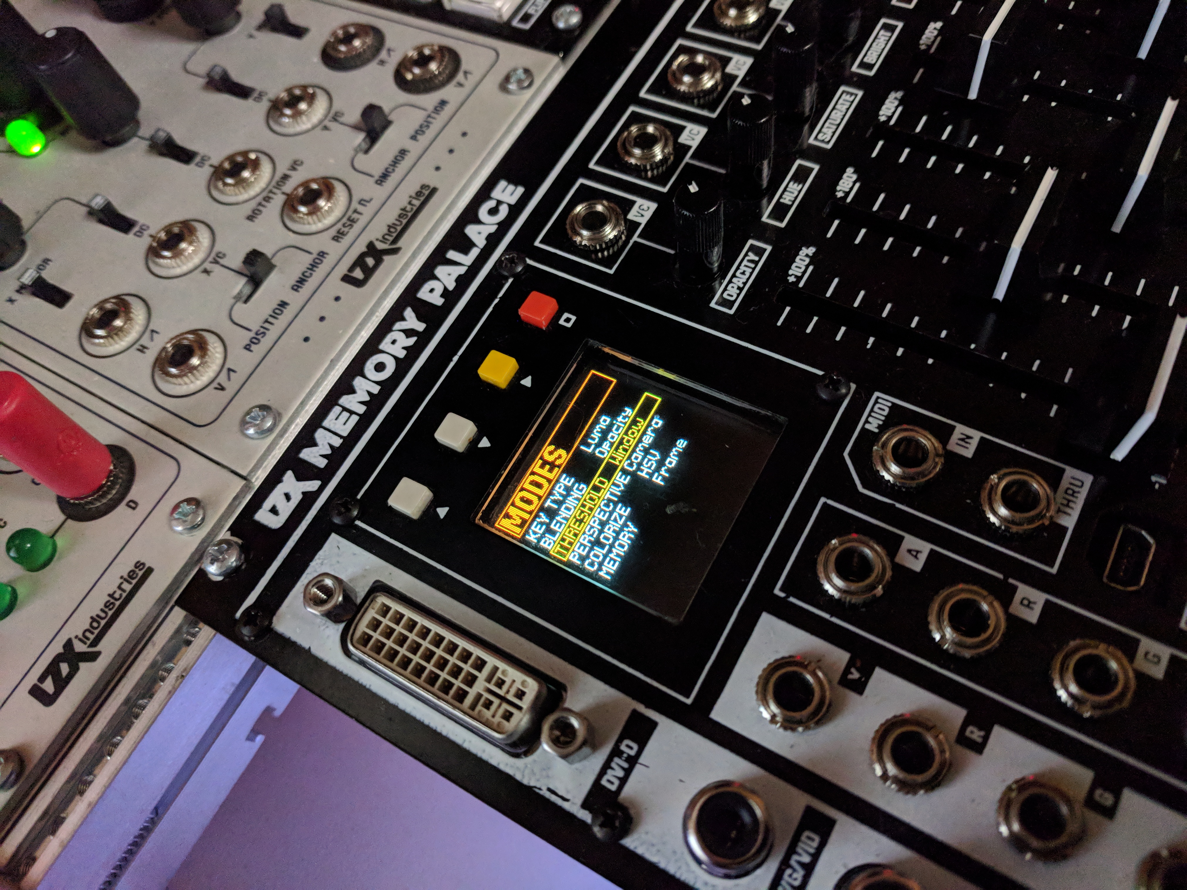
That display looks fantastic! Simple, E-Z to read layout. More and more psyched every time I get another glimpse.
Thanks! We just finished making custom fonts today. This view shows the current version of basic parameter selection screens, but some pages will also have animated elements (that respond to the sliders) and we’re hoping to get full speed video preview going as well. The OLED really looks stunning in person.
looks very nice thanks for sharing
Is the soften circuit similar to edge feathering or even across whole image?
That’s the edge softness of the key.
Memory Palace Specs & Feature List
Basic lists of features and specs, as well as some simplified routing diagrams have been posted here:
Memory Palace will have the same user reference card type of document as recent Expedition modules posted in PDF format before release. Please feel free to comment here with any questions.
Thread Replies
I would like to know if all buttons are toggle or if make sense or ita possible to have some buttons as momentary (effect its only active wjile button its been pressed, when release the video returns to original state) another question I have is effects/mode buttons can be used with some sort of transition or easing or instantaneous the change when the button is pressed? if so th transition speed could be configured?
I would like to know if all buttons are toggle or if make sense or ita possible to have some buttons as momentary (effect its only active wjile button its been pressed, when release the video returns to original state)
By default they are all 2-state toggle based parameters, but I don’t see a problem with putting momentary behavior as a configuration option on our development list.
another question I have is effects/mode buttons can be used with some sort of transition or easing or instantaneous the change when the button is pressed? if so th transition speed could be configured?
No, all of the transition based parameters are on the sliders with CV inputs already. The buttons are only used for parameters that have a binary state. If you want to transition from one of the binary effects to unaffected input, this is what the keyer (and alpha channel input) are designed to do. Or external compositor.
I do like what you’re suggesting – it’s similar to the intention behind the pushbutton control for the animation generator on Visual Cortex (push to transition, use rise/fall to set easing and transition speed.) But in terms of the LZX system architecture, it’s something to put on an animation envelope / sequencing module to be used as a CV source.
With the internal feedback loop, each control cascades to a series of related actions in the buffer repetitions – so there are many very performable transitions just with slow slider movements; especially moving two sliders at once, or moving one slider with LFO modulating another, etc. With analog we are used to creating or altering just a single element at once when a knob is turned, whereas in the buffer feedback context the echoes create a whole sequence of complex movement based on simple input motion.
I’m curious about powering the Memory Palace via 12V DC auxiliary power connector to “reduce drain on your EuroRack”. Does that mean you can power it entirely via auxiliary power, or would you still need to connect it to your main PSU for additional power?
I’d love to know too
with the liquid tv you can power it externally but it still needs to be connected up to the euro power rails
I’m pretty sure I read somewhere that the 12v dc is for the logic board and you still need to power the control board from eurorack rails, but I might be wrong
My understanding, which might not be full, is that the Liquid TV needs to be attached to euro power for sync purposes, even when powered by an external 12V DC connection.
You still need connection to EuroRack rails. Using the external 12V connection is for cases that might otherwise be strained on power load – when used, the EuroRack power draw drops from +450mA/-40mA to +/-40mA. If you have a EuroRack power supply that takes a 12VDC brick (like Malekko Power) you can use the same brick to power the Memory Palace and your Euro supply (Vessel makes this easy, with its internal DC barrel connector, you can just use a 1 ft’ 2.1mm barrel cable, like used on guitar pedalboards.) So essentially it’s the same deal as with Liquid TV; a way to offload the excess current taken up by the displays and digital circuitry.
I have a couple of these and imagine they are up to the task.
You will only need 12V 1A or so, for external 12VDC adapter. Look for the ones sold for CCTV systems. This one for example, looks great:
Those Johnny Woods intro videos are really nice! Always great to see someone step through features one-by-one.
So many interesting possibilities with MP!
Just a heads up, the link in the OP no longer works.
+1 on the intro videos. Those got me drooling. Very easy to follow, I wish he could make videos like this for every LZX module!
Hi @creatorlars! Memory Palace is amazing. Great work.
Feature request: Would it be possible to configure its YRGB outputs to send ramps and sync (2x ramps, 2x sync)? Especially when using MemPal as the last step in the chain, this would be a super handy way of getting these signals w/o needing those extra modules in the case (for me anyway :D).
@giantmecha No I’m sorry, that feature is not possible. The YRGB outputs will always be showing the same color video source as the CVBS/S-Video outputs (it’s the same encoder chip for the YRGB and CVBS/S-Video outs, they’re not individually addressable). Memory Palace is not a standalone module, it is an expansion module for a system that assumes Visual Cortex as the core module.
Ah okay, gotcha. Thanks for the speedy reply! I’ll figure something out.
You could get a Cadet I Sync Gen + Cadet IV Ramp Gen to get those functions in 8HP.
As a standalone unit, the MP’s stills loader could replace the ramp gen in some ways.
Here is another feature suggestion for the ‘stills’ menu.
Currently when selecting the image still, with the arrows you select/toggle between folders and the image sections, and then if you press the yellow square button you change either the folder value or go to the next image on the current folder.
My suggestion is to swap the controls, to use the up and down buttons to move between images or folders, and the square yellow button to toggle between folder selection or image selection. Its a bit (not a lot) annoying to do a lot of clicks on the yellow button when the images you just loaded is the previous one since you need to fully cycle all the images in the current folder… the same will happen when we have too many folders.
will/can the memory palace accept HID messages? I suppose I could wrap something in max or PD to output MIDI instead
Is there a “hard reset” button combo for the MP for when it crashes? Or just best to turn the case power off and on again?
Why or when is it crashing? Make sure your case has enough current and that there is ample airspace around the rear fan. The only crashes unrelated to power we’ve had so far have been related to the SD card interface.
I think it’s happened twice now. Not sure what prompted the first one, but today’s was a patch with lots of feedback, and then (accidentally) hitting the A/B button…it crashed on a very feedback-y frame and I couldn’t get it out of that state. Added up the power and it should be okay, and I think there’s plenty of airspace.
Cool, that does sound like an SD card interface related glitch (when you hit any button, there’s an SD card access and save state.) We should have some of that cleared up in the next release, but admittedly distracted by production and end of year accounting right now. Can’t wait to get back to Memory Palace.
Okay cool, good to know. Will keep you posted on any more crashes as they arise…
MemPal is so dang cool, thanks for your amazing work. Barely scratching the surface.
@wednesdayayay One of the big sprints this year on Memory Palace will be to get some USB host drivers running for USB MIDI, USB HID (I want a trackball!), and potentially USB Video Class. So not yet, but it’s on the agenda. A lot of this stuff will be developed in tandem with TBC2 and future Orion Class III modules, as it’s one of the ways we’re able to fund development, is to treat it like a group project for the whole series.
A trackball would really tie the room together.

Single link. Dual link is used by graphics cards that can use a splitter to send separate video feeds to two different monitors.
DVI doesn’t take audio, that’s just for HDMI. If you need audio, you can use one of those HDMI audio splitter thingies (haven’t tried this one, but there’s lots out there):
@creatorlars what about statut leds in the back panel, could you describe fonctionnality?
In my mind the straigh way to do it is using an arduino, mixing PS/2 and midi librairies… If I’ll get some time I’ll try to make something (I’m working now on a Nunchuck Wii controler to midi hiRes to drive MP)
The status LEDs are for Power, FPGA Config (turns on once FPGA has booted up) and USB activity.
That’s the Deadband value in the slider settings adjust page. Larger value will increase the size of “zero” in the middle of the range. You can adjust s-curve response and slew on that page as well. We’ll have the ability to disable or reposition the colorspace converter in a future firmware update.
Using ESG3, TBC2, or Chromagnon in HD sync modes: Compatibility with earlier LZX modules and instruments
Here are some guidelines for using ESG3, TBC2, and Chromagnon with earlier generations of LZX modules and instruments:
-
ESG3 has 15 different video sync modes. 2 of those modes are NTSC and PAL. ESG3 is fully backwards compatible with all previous LZX modules, because it retains the NTSC and PAL sync modes. So to use it with older modules, run it in NTSC or PAL sync modes.
-
ESG3 does not add 13 new sync modes to older commands. In order to use ESG3 in HD sync modes with older systems you will need a video scaler / format converter (such as TBC2) to upscale your NTSC or PAL system’s output to the HD path.
-
There are tons of exceptions to the guidelines above! These all fall in the category of analog modules which don’t even rely on video formats or sync – or with some that have such simple needs for their sync inputs, that the NTSC/PAL sync separators are able to decode the HD syncs.
Here is a list of HD compatibility rules of thumb, in the absence of a more detailed compatibility chart:
- Anything with a video output or input on it: Memory Palace, Vidiot, Visual Cortex, for example – definitely won’t work in HD modes.
- Something that runs direct off of discrete syncs, like Prismatic Ray, War of the Ants, or Fortress, might be partially compatible with some of the HD sync modes. Try it and see! Post the results here on the forum.
- If there is no sync input or output on the older module, it likely will work fine in the HD sync modes.
General advice for system building:
- Keep your NTSC/PAL video synthesizer the way it is, and start a new video synthesizer for HD workflows. Use a module with upscaling capabilities, like TBC2, to send the NTSC/PAL video synthesizer’s output into the HD signal path.
- Stick to NTSC/PAL if adding Gen3 modules to existing systems.
- Try out HD if starting a new system with the Gen3 commands.
- Upgrade your existing system to Gen3. I’d do that by starting a new Gen3 system, and then transferring the older modules to it that are working well for your Gen3 workflow, integrating them one at a time.
I would love to answer any questions.
Thread Replies
+1 for a compatibility chart! I think it should be kind of like an emulator compatibility chart… not just “works/doesn’t-work”, but something like “perfect/good/poor/doesn’t-work”, with notes for any status other than “perfect” if necessary. Although I guess it gets a little complicated since there’s so many modes in the gen3 gear, maybe? I guess the notes part might need to be dropped.
@creatorlars Is this a good thread for people to comment about their experiences? Or do you want to keep this thread to a Q&A kind of vibe?
Discussion is great! The purpose of this post: make it easy for other community members to gain access to community knowledge on this subject.
Regarding data structure for a compatibility matrix, it is kind of tricky. Given the number of formats you could test in, and the number of modules, and the obvious benefit of logging notes from multiple user reports in any of these cases, the data is like a cube – and that’s not easy to represent in a single table. Maybe there’s a better way.
We could use the forum’s tagging system, and then perhaps provide an index and “ratings chart” in this thread or one like it. For example, all posts tagged “Navigator” and “Gen3” is a good indication of user reports on Navigator’s compatibility with Gen3’s HD modes. This makes the forum’s search functions more powerful.
Although this is a topic about formats, I think power would be a useful dimension especially for the system building topic.
When building a 2x84HP or bigger system, with mostly but not exclusively Gen3, it seems difficult to get around having 2 types of power supplies (a bus board and a DC distro or cheaper alternative). In that case the potential of Gen3 offering a more affordable power solution seems lost. Especially if we don’t want to introduce any noise form cheap power supplies meant to power only a couple of non-Gen3 (/non-LZX) powered commands.
Curious what you recommend or how others are planning to do this.
I’ve just added a DC Distro to the PSU2/PSU3 cases that I’ve been using. I’m committed to a mixed case for a while because I love the vibrance of the DIY scene and the legacy modules are all fairly distinct from their Gen3 replacements.
I would either have 2 separate cases (one DC Distro, one EuroRack), or a rack case with multiple rows (some rows EuroRack, some rows DC Distro), or if a single combined case was a must, I’d install a EuroRack power supply/busboard with enough 12V DC current to supply both EuroRack and Gen3 commands. It’s also a question of proportions. If you’re just putting a couple of Gen3 modules in your existing case, powering them from the EuroRack shouldn’t be a problem in most cases.
Cheaper input power supplies is only one reason for the Gen3 power distribution scheme, that’s only part of the puzzle. Some of the modules are massive analogue circuits, and just require more power in general. Making them possible as low HP modules is quite a task, and so I don’t think there are any off the shelf EuroRack supplies that could handle an all Gen3 system.
will the LZX euro power supply be coming back at any point?
I’ve got one of the LZX power supplies a 5a dc distro for the big modules and a 3a dc distro for a row of regular gen 3 plus a 4ms black row power that I’ve used for a long time but is kind of noisy. So I think I should be set for the moment to get things rolling again.
the skirting and stairs on our new house should be finished by tomorrow so we should be moving in in the next couple weeks! Then once things are moved in I can start setting the dedicated space up again. I’m so pumped to start streaming with a system again. I should be getting a package from LZX today with a bunch of good stuff.
We could do a combined EuroRack and DC distribution busboard at some point, likely when we offer a new version of Vessel or a new case. But it would be a higher priced variant than the base option, which would be DC distribution only. It would be very good to hear everyone’s thoughts, complaints, desires, etc for all of these solutions as you confront integrated setups. What percentage of a system is going to be Gen3 vs earlier generations of modules, for example? If it’s 90% Gen3, a couple old modules, that could be annoying. If it’s 90% old modules, a couple Gen3 modules, then most Euro supplies should be fine. If a new busboard design (Euro + DC) is something that solves a lot of folks issues in the short term, we could prioritize that.
We’ve tried to engineer a low impact solution that solves basic Euro power vs Video modules issues that have been around ever since the introduction of non linear power supplies and shallow skiff cases into the EuroRack landscape (something that happened in early 2010s, between Visionary and Expedition series.) Even with linear supplies, distributed +/-12V always proved a big problem for us, since any modern (past few decades!) video parts run off of +/-5V.
So high power, ultra low noise, miniature-scale form factor – it’s a tall order! There are of course going to be some integration road bumps – our hope is that our solution is a balanced one, that allows the growth of the format and systems, while still allowing integrated systems rather than ditching EuroRack power entirely.
changing from PAL to 1080i60.
esg as master sync to cortex.

That all looks as expected. Visual Cortex does not support 1080i60 modes (it runs in NTSC or PAL only).
More on this point. I don’t think you’ll suffer a decrease to any existing EuroRack power supply performance when using distributed DC 12V in the same case as EuroRack commands. The DC 12V entry never touches the analog signal path – that’s all being powered from the rear power entry board on the LZX commands. On that board is a big EMI filter right at the input, and a power supply topology that produces very low noise +/-5V rails (and those are what power the IO and the rest of the signal path.)
If you are seeing some kind of noise like that with DC distribution, make sure you are using shielded jumper cables and that all modules are secured to the case with mounting screws. If you’re still seeing some kind of noise, give us all the details on your setup so we can try to recreate the issue in the lab.
What I mean is, if next to a couple of Gen3 + DC Distro (or other supply) modules, you also have a non-Gen3 module that is powered by a different very noisy power supply. Maybe I’m misunderstanding but if that noise has entered the patch via one dirty power supply, it will not be filtered by the Gen3 modules anymore, right? Or do all signals you patch go through those EMI filters?
Ah okay, I get you now. And yes, that’s correct. You can’t expect the Gen3 modules to remove any noise from other commands. So it’s best that you always use a lower noise EuroRack power supply, same as it’s always been, to get the best performance out of EuroRack powered commands.
Has anyone used Castle modules in HD workflows? I’m curious how those do.
Used caste adc and dac. They work as expected with some rough edges
susynct - thank you for a needed boost of confidence in the upcoming merger
There’s no inherent reason the Castle modules, apart from Castle Clock VCO, won’t function correctly in HD timings.
Castle Clock VCO expects H/V sync on the CV/Gate power connector which is a deprecated standard in Gen3.
To get H/V sync into the Clock VCO, simply take a H or V ramp from DSG’s SUM output (use a dummy cable to disable the other ramp), sum it with an adjustable bias (Passage, Proc, Fox Access, etc.) and plug it into the front panel’s Sync input. Same principle applies for syncing any oscillator that doesn’t have an RCA connector. Cadet IX may be modified for a front panel sync input.
You can use the same H/V ramp + offset approach for any of the other Castle modules with Clock or Reset inputs that can benefit from being locked to H/V pulses.
https://community.lzxindustries.net/t/tbc2-aka-bell-tower/319/67
I am hoping this is still the case, however.
Yes, HV sync outs are available on TBC2, same as Cortex. (The 2-position DIP switch enables HV sync to the CV/Gate bus on the EuroRack power header.)
Very good. That solves a sync problem that’s been bugging me. Thanks.
By this I guess you mean composite sync is available on the power bus, for compatibility with legacy video commands. TBC2 does not currently provide separate H or V sync outputs either at the front or rear panel, right?
As I mentioned previously, it would be super sweet to have vertical sync available as a patchable signal, for purposes of vertical interval switching, oscillator and envelope triggering, and full frame/field sample and hold. I’ve made this work with Syntonie video sync’d oscillators, and it’s awesome. But it would be even better if I didn’t have to tie up an entire oscillator and comparator just to provide vertical sync to a sample/hold trigger input.
Which also brings up the question, what is the square wave input on the front of TBC2?
Thanks!
“HV sync over power bus” refers to the older sync system used for the Gen1 oscillators and early Prismatic Rays.
Assignable trigger function input, like Memory Palace.
By this I guess you mean composite sync is available on the power bus, for compatibility with legacy video commands. TBC2 does not currently provide separate H or V sync outputs either at the front or rear panel, right?
Correct. There are no 3.5mm patchable syncs on the front or rear of TBC2.
There’s an HV ref / sync generator module coming, which will have discrete sync outputs and HV reference ramps. Unlike previous generations, a module like this isn’t required for every system, since modules like ESG3 can also function as a standalone sync generator.
That’s awesome… but I’m out of rack space.
Any chance you’d be willing to make Vsync available from TBC2 Y output via a firmware update?
Thanks!
The Y output is an analog sum of the RGB outputs, so addressing it individually won’t be possible. It is possible from the RGB outputs, by purposely misaligning the start of active video with the start of the sync interval. So it could be in a list of things to consider in a future firmware version, but beyond the scope of the initial release. You can get creative by syncing things off of the image loader in the meantime though. Just make a still image with the top scanline white and the rest black, and that will create a vertical reset pulse. If you do this with Red line on top, Blue line on left, then you will have some usable HV syncs out of R and B jacks.
Will this module also output the HV sync signals through the power bus? That would be wonderful.
No, not unless we included an extra/secondary Euro power header (maybe there is room.) We took a lot of care for the Euro header to only touch the internal circuit thru its 12V connection, which goes thru the EMI filter. A buffered output coming from the core board (on a separate Euro connector) might be possible. A module that is specifically a legacy sync adapter might be the right answer, for that and 14-pin sync.
ZOMG you just blew my mind. That is so clever. Too bad it ties up a whole TBC channel. With a Chromagnon and a Syntonie decoder I should be fine, though.
But the headline here is actually “RGB channels carry arbitrary information”. In the digital graphics world we use channel packed textures all the time, carrying arbitrary parameters such as roughness and metalness in stacked channels in RGB files e.g. PNG. Now I’m realizing that can be applied here.
In combination with other tools e.g. Color Wheel we can do some really creative stuff with channel mapping, color space conversion, color correction etc.
I’d love to try processing footage in hardware or software to convert to and from YUV and HSV. Maybe there is a way to make the decoder outputs and/or encoder inputs handle YUV.
Exciting stuff!
Is there a limit to how many modules you can sync with one sync generator? Could you build a huge wall of DSG3’s synced to one ESG3?
Is there a limit to how many modules you can sync with one sync generator?
No limit… in Gen3 every sync node is buffered, so the transmission lines between modules should perform identically no matter how many modules are in the chain. No more loop thru weirdness woes.
Could you build a huge wall of DSG3’s synced to one ESG3?
Yep! During testing, I had 5x DSG3s and 5x ESG3s all synchronized at the same time.
Yes! Once it’s a voltage in sync with the video frame, the sky’s the limit. You could encode not just sync pulses for oscillators, but different sync patterns in an image. So “image loader” seems like a mundane feature at first glance, but in our context, it’s wildly powerful.
Yeah, we could for example make a still image that has H and V ramps plus a wipe gradient, each in a separate color channel!
much like what is covered here LZX Video Synth Techniques: Gradients - YouTube 
I was hoping to jump into the HD arena as well but have mostly Cadets and a Vidiot. I know the Vidiot is a beast that will forever roam SD land, but I was looking at the schematics for Cadet IX and Cadet IV to see whether it would be possible to cobble some HD into them or if my system would need a total upgrade.
On Cadet IV, C18 and C29 could probably be swapped out for something smaller to generate the appropriately sized ramps, yes?
I think Cadet IX should be okay (unless the timing cap here is also too large), but perhaps the op-amps on the exponential converter would need to change over to something faster for HD FM inputs? I remember LM6172 not being recommended in place of the TL072s in this case – there was a better suggestion earlier in the forum I can’t recall off the top of my head.
Forgive me if this has been answered already elsewhere or if I’m barking up the wrong tree!
That should work, but you may run into an issue finding perfect cap values to replace them with.
Let me run a simulation real quick… (time passes)
This is directly from the Cadet IV’s schematic (The H-rate section). The trimmer (R1) is for adjusting the ramp’s peak to exactly 1V.

If I change the sync rate from 15.734KHz to … 33.75kHz, then a cap of about 22nF to 24nF results in close to a 1V peak. 24nF is about the highest you should use since the tolerance of any given ceramic cap might be 10- or 20% higher.


Tayda has 18nF and 22nF ceramic caps, so it should be easy to find one that fits. The trimmer, R1, should let you trim it to 1.0V even if you’re use the 18nF cap.
Changing the cap is the easy part. Getting the HD sync pulses on a 14-pin ribbon cable will be more difficult. @joem may be working on this though.
The timing cap will still work. You will just be limited by fewer bars. Changing the cap with the ratio we used above should get you fixed up.
EDIT:
I corrected the H-rate pulse width in my simulation to 525nS as listed in the LMH1980 datasheet. This changed the perfect cap value closer to 27nF. 18nF should still work since the R1 trimmer allows for such a wide range of attenuation.

Indeed I am. I’ll update in that thread sometime soonish hopefully when I have some more progress.
That’s amazing, thank you very much @Fox!
And yes, I was/am indeed watching @joem’s project intently

For the record, I found the LMH1980 datasheet to list tHSOUT for an HD, H-sync pulse width as 525nS, not 4.7uS as I had originally simulated. The best cap value is now 27nF. 18nF will still work since the R1 trimmer allows for such a large range of attenuation.
That 525ns is the propagation delay to expect between input and the logic outputs in the SD input modes of the LMH1980. This equates to exactly 10 clock periods of the 27 MHz pixel clock. (That’s what I have programmed as the correction factor in ESG3 firmware.) The actual HSYNC period for HD is about half of the period for SD.
A good way to do the 14 pin sync adapter would be with an embedded fpga sync generator to generate the pulses and genlock to an external source. So it could be implemented with the plugin syncgen boards from the ESG3 or the VU007B I reckon.
LMH1980 generates both HSYNC and VSYNC, and auto-detects between SD and HD, so it’s a good option if you want to integrate sync separator directly into each module.
Ah-hah. Thanks for pointing that out. 525nS sounded a bit too short, but I am still reading about the finer details of HD sync.
I am still a little confused with the LMH1980 datasheet. tdHSOUT is listed as the 60nS propagation delay and tHSOUT as the 525nS pulse output.
When considering a ramp, should the falling edge of CSOUT trigger the shorting of the cap and the rising edge of the BPOUT begin the charging phase? I was only worried about HSOUT, but tri-level sync is different than SD.


You’re right on the timing details! I was mixed up on the SD vs HD timings in my head. 525nS is right.
For ESG3, we have the HD pulse width set to 44 cycles of the 74.25MHz or 74.176MHz reference clocks, so ~590ns.
That becomes very tricky – the right answer is that you start the ramp on pixel #1 when the AVID region goes high – and that timing is variable per video format. So it’s not something you can get a precise reference for from the LMH1980 alone – you’d need to tune the ramp start phase per format to get it perfect (maybe adjustable monostable delay of HSync with a trimmer?) Easier to base this on a sync generator/FPGA that is responsible for all of the timing. This is ultimately why we didn’t go with an analog PLL based ramp generator for DSG3 – we had an “auto calibrating” ramp circuit working beautifully, but the blanking periods would have had to be manually adjusted.
That said, all you need for a “working” ramp generator is a stable hsync reset – it doesn’t have to start exactly in the right spot to be patchable!
Hello everybody!
I’d like to connect Vidiot mini jack outputs on the panel (i.e. the diamond output) as video source for ESG3. I set the format switch to PAL.
However, the diamond shape image is not synced and it is scrolling left to right.
How to stabilize it?
thanx! : )
I don’t have either - but, you’d need to connect sync out from esg3 to a sync in on the vidiot
As far as I know there’s no sync in in the Vidiot…am I wrong?
I checked the manual - you could try the horizontal sync input - page 7/8 of the manual item 18 - worth a try at least
or see page 13!
I believe you can send the sync from the back of the ESG to the camera input of the Vidiot.
Or you can send the the Vidiot’s video output (or maybe the Eye output?) to the sync input on the back of the ESG.
Or if you have something connected to the Vidiot’s camera input, you can send the camera output to the ESG.
You’ll have to set the ESG to generate or receive sync accordingly.
Thank you it works by VIDIOT camera output to ESG3 sync input!
That’s how I sync my system
If you are using ESG3’s component output for monitoring, you can also send it’s composite output to Vidiot’s composite input for sync. That also gives you an optional feedback output from Vidiot, if you want it.
Would using the ESG3 as an output module for Rutt-Etra type stuff make any difference/sense?
I mean using the HQ mode.
Just ordered one in order to get better quality video out from my setup and haven’t looked into the other possible benefits and use cases yet.
It’s been a while, hello everyone!!
Welcome back! Are you using any older LZX modules in your vector rescanning patches and want to work ESG3 into the mix?
Thanks!!
Yes. I’ve got the usual suspects: VC, Passage, Nav and Shapechanger.
If you are using Visual Cortex as part of your patch, you will be limited to NTSC/PAL when syncing your ESG3. I don’t think you would see any change in your vector rescan workflow by adding ESG3.
That makes sense. Thanks!
Actually I do have the TBC2 so by using that the only thing coming from the VC would be the ramps.
Well the ramps are synced, so anything out of the Cortex is still limited to NTSC/PAL. However…TBC2 makes its own ramps, so you would have an HD ramp source there. TBC2 can replace Cortex in your rescan patches.
I will definitely give this a try.
It would be interesting to hear from someone who has done this with the new modules as of how noticeable the difference is.
TBC2 is good for HD ramps, I have tested this in a vector scan processing workflow.
If you care about the cleanest possible ramps, with no crosstalk, follow this procedure. Crosstalk between ramps will manifest as skewing of the raster, it won’t be perfectly rectangular.
Use one channel of TBC2 for the video image, if any.
Set up the other channel of TBC2 to output ramps. One of them on the Red output, the other on the Blue output. Turn the Green output off entirely… disabled.
But you know what, I got more control by using DWO3 or VU009 sawtooths to generate ramps. If you’re not able to get a single sawtooth cycle out of DWO3, send a static voltage (e.g. Matte) into the CV input and set the attenuverter to negative. This will slow down the oscillator more than you can by just turning the frequency down all the way.
I was wondering about HD vs SD ramps within the context of vector rescanning and lo and behold, it’s actively being discussed here. I’m considering buying a TBC2 for many reasons, one being the ramps.
Right now I use both VC and Diver as ramp generators. Doing a lot of rutt etra type stuff with external video/images, but also stuff without external inputs (shapes, patterns etc generated within the system). I don’t want to change my workflow for the rescanning portion (I’d like to keep what I’m filming off the X-Y displays as SD, so I can process the rescan video with all of the normal SD LZX modules, rest of my projects are in SD as well) but if I could increase the resolution of the ramps in my vector patching (using ramps from TBC2), I’m assuming I’d get a lot more detail within whats displayed on the vector screen itself… am I understanding that correctly? Almost as if the “fabric” that is the ramps is larger, or to put it another way, if the gain wasn’t adjusted on the display the ramps themselves would be much larger.
I use navigator pretty early in the chain in nearly every vector patch, would still work to rotate the TBC2 ramps? It’d need to be synced to TBC2?
Very basic example of what I’m envisioning:
TBC2 (Set to an HD resolution)
Encoder A- R (h ramp) G (v ramp) B (n/a) (as described by dryodryo above)
Encoder B- media loader high def sized image
Both Encoder A H+V Ramps to Navigator (synced to tbc2?)
Navigator outputs to 2 cadet crossfaders
Encoder B image mixed in to taste for displacement effect
Crossfader output to X-Y display
(And run the Luma from encoder b the TBC2 to the Z input)
X-Y display rescaned by SD camera
Colorized, keyed to taste, etc etc then output by VC
So I guess I’m kinda suggesting an HD path to the XY displays then a seperate SD path for rescanning. In my head it makes sense that there’d be a big difference using these ramps instead, HD video is much larger, but I’m not sure if it translates the way that I think it does.
You could also use Angles for ramps. NGL, TBC2 ramp randomize function is pretty fun.
Your display’s Z axis may not be able to cleanly resolve HD luma as I don’t think I’ve seen a vector monitor that can do over 10MHz on Z. The output impedance of your modules also makes a difference in whether the available details are cleanly output or simply low pass filtered.
If you are rescanning in SD prior to encode/capture, I’m not sure you’ll really be able to tell a difference regardless of how sharp HD ramps/footage appears on the monitor. You’re effectively downscaling at your colorizer/encoder stage with VC.
Post some comparisons if you end up going down this route!
I’m not 100% sure I completely understand all of that, but I can offer a few thoughts. Everything @rempesm said is true, I just want to add a couple points.
Vector monitors with a bandwidth higher than 10 MHz don’t exist, but XYZ oscilloscopes do. I have one that has 30 MHz on the Z axis. But it’s a moot point if the dot size is too large relative to the screen size. That’s the limiting factor for the vector display part of the patch.
HD ramps will give more detail than SD ramps. This is a big aesthetic difference, because SD ramps will more clearly “delineate” the lines of the raster. In my experiments with HD ramps, I’m getting much softer, ethereal, gossamer translucency rather than visible scanlines. The raster is rendering much more as a surface than as a bunch of lines. But this is also dependent on your settings. Suffice to say that an HD ramps setup can achieve some of the characteristic “looks” of an SD setup, but not so much the other way around.
In my experience, the performance of TBC2 as an up/down converter leaves something to be desired. I’m seeing it drop frames all over the place. So in any event, I recommend keeping everything in the system in the same format: camera, decoder, and encoder. As @rempesm points out, the Visual Cortex is the limiting factor here. ESG3 or Chromagnon is what you need if you’re trying to get more detail in the final product.
Also, a genlock setup is preferable to wild sync into TBC2. I’m getting frame tearing. A camera genlocked to TBC2, or a whole system genlocked to the camera via a Syntonie decoder, should solve the frame tearing issue. I guess this might also work by sending a copy of the camera’s composite or Y signal into the TBC2 Sync input? More experimentation is needed.
Good Day,
For the record- Chromagnon has NOT shipped right? I’ve moved twice since I Bought it however many years now. 4-5 I take it. It’s hard to keep up. Thanks
Ofield
Memory Palace Firmware Update Guide
A new Memory Palace Firmware Update Guide has been posted below. This should explain the extra steps required to update from V18 to V19 clearly. Please comment below if you have any problems at all with the update process. If you already have V19 and are upgrading to a newer firmware, simply copy over the BIN file to Memory Palace and select “Update Firmware” in the System menu (then choosing the location of the new BIN file).
Thread Replies
Hello ,
I followed the instructions on the pdf and my module still gets stuck in the SYSLOG loop.
No matter how many times I turn off and restart the module holding down the Boot MicroSD button on the back.
I am using a MacBook and read To use a app to clean the Mini SD card.
I have done that and it still does not work.
I noticed that my Memory Palace PCB is marked 2018. I don’t know if that has anything to do with it?
As on the instructions it says Upgrading from 2019 Production Units.
I have done all the procedures of taking the SD card out and loading the software on it. Also loading the firmware from the front USB port. I see it gets written on the card.
Might be best to send your unit back to us so we can see if there’s something else going on! It sounds like you’re doing everything correctly. Please send an e-mail to support@lzxindustries.net to arrange an RMA.
How to tell which firmware version I have?
Does it start up in the PARAMS menu? Do you have Ghost mode? If so, you have V19.
Yes and I have Ghost mode; thanks
Ive downloaded the upgrade onto my mac.
It didnt recognise MP through the USB connection so I was forced to take out the sd card and download it onto that.
I followed the instructions, deleted old files and loaded new files.
While placing the sd card back in the holder the metal flap dislodged. I was able to get it on again and the card is situated where it should be.
I followed instructions to update firmware:(Press the hollow square orange button)
It stalls for about 4minutes and then goes to the main screen, doesnt restart.
I navigate back to Update firmware and the menus contain undecipherable icons. Something is corrupted!?
I have a 2019 unit and I dont see any messages that internal memory must be initialised.
What can I do?
Could you include a photo of the weird icons you are seeing?
Ive reloaded the Sd card from the downloaded file. Is it supposed to look like this?

The funny characters dont appeat anymore but when I upload new firmware in the menu it stalls then shuts down for about 3minutes. The fan and lights on the back are still on though.
I took a video of it but this forim doesnt allow vids. Maybe put that up on fb community?
When it comes back on it doesnt go through the Memory Palace splash screen but goes straight to the menu.

I wish I could do the usb method, opening up the metal door on the sd card gives me anxiety, I fear Ive damaged it already, it doesnt click into place as well as it used to.
Did you run CleanMyDrive2 on the SD card after reformatting?
Did you power on the module while holding down “Boot from SD” and the red and yellow buttons (simultaneously)?
It seems reformatting and cleaning the drive was the guidance I needed. Its working now, thankyou.
Perhaps its obvious to do this but for me it would have helped to have this info in the update guide .pdf so I didnt need to waste your time.
Thankyou
Sorry about that. It isn’t always necessary, but seems to help some Mac users.
The clean my drive solved a bunch of issues for me as well.
i never got this new firmware working/ loaded .i just gave up on trying to update it.
As i am using a Apple and tried the clean my drive app and everything i could think of.
Mailing it to lzx just for a update during covid19 and the postal service being sketchy is a bad idea
You can send it in with FedEx or UPS
Is there a way to tell what firmware version one currently has in memory palace?
Could you share a photo of the System screen? The current V2.0.1 beta firmware will show the version on the system screen, but V19 does not.
I figured out I have V19 and will soon try V20. In any event, I was surprised to see that an earlier version is much easier to read…
Hi friends,
I have a 2018 Memory Palace, an early preorder unit. Attempted to update the firmware today on windows, via the USB port on the front. Followed the .pdf instructions, and am stuck in the SYSLOG loop, pressing and holding the Boot from SD button doesn’t seem to help.
Has anyone resolved this issue? Much appreesh.
Resolved the issue by holding the Boot from SD button, and the yellow and orange buttons, while having my significant other power on the case. Perhaps this could be added to the guide for us crustly old 2018 folks.
So I am still trying to update my old 2018 memory palace to the v.19 firmware. I keep getting stuck on the SYSLOG loop.
I tried you method of holding down - Boot Micro SD button ,Yellow and Orange buttons on startup.
I saw new screen saying updating “firmware will take a few moments” after that the module goes back into the same SYSLOG loop.
I don’t feel like sending my module to LZX due to slow shipping system of Covid.
And I really want to try out this new to me settings on the V.19 firmware.
How did you get past the SYSLOG loop?
please help.
I feel like smashing this module with a bat everytime I see that SYSLOG message
Let’s get you out of the woods. First, do you have the module set to internal sync, with nothing patched to it? Did you use a Mac or PC to update the firmware?
Hello,
I am using a MacBook Pro (13-inch, 2017 - 3.1 GHz Dual-Core Intel Core i5
I have nothing plugged into the back of the module besides the power connecter.
I have set the sync to internal sync - external. Whatever setting I still get same result
I followed the pdf on updating firmware exactly as described . I get same result.
I have tried the sd card method . Same result.
I tried holding down Boot Micro SD on start up. I tried holding down yellow and orange on start up. I tried hold all 3 of them down on start up. Same SYSLOG message.
I have formatted the SD card using the “Clean my drive” app. I trashed every single thing inside the folder.
Still get the dreaded SYSLOG

here is a picture of the switch setting if it would help:


you might try terminating your sync by setting the EXT SYNC switch to terminate (rather than loopthrough)
since you aren’t sending it anywhere in this instance
I don’t think that should be causing this issue though
I am using the sync signal coming from Visual Cortex which is going to Memory Palace and then Navigator.
Would I still have to set the EXT SYNC to loop thru though? or Terminate?
I guess I’m confused how can you have nothing but power but also sync coming in from VC and going to nav?
you can totally using memory palace like this in fact that is how mine is set up (not master and passing sync through)
but if you are troubleshooting I would unplug all of that and just try to MP by itself 100%
when i am using the memory palace as a normal module doing video synth stuff. i have the Visual Cortex as the master sending the sync signal to Memory palace. The sync through rca jack is then connected to Navigator where the sync signal ends.
When doing the firmwarw update i unplug all the rca cablesand set memory palace to internal
The error message makes me think that there is some other issue with your Memory Palace. Could you send an email to support@lzxindustries.net so we can set you up with an RMA?
Is it possible to downgrade firmware? Many of the tutorials are using the v1 and I’d like to match whats being shown.
Recent LZX entrant asking/musing about a couple things
Hi everyone, I’m a very fortunate recent entrant into the LZX ecosystem, in that I acquired a Visual Cortex, and have been enjoying exploring it.  I found Shawna Lee’s VC/Vidiot video, and was taken with quite a few of the patterns, shades, and textures in it. https://www.youtube.com/watch?v=_sZ2DDvdkvk I’m sure the Chromagnon could accomplish this and more with the VC, though I’m interested in expanding my LZX set sooner. If I were to choose some Gen3 modules to do similar things, do you think the DWO3 and maybe the FKG3 would be the first choices? A few time markers that caught my fancy were at 2:00, 3:00, 5:30… I’d like to be able to CV some of those sections that she was adjusting via knobs, especially the 3:00 one. This seems to be adjustment of oscillator frequency–gentle FM of DWO3 might do this?
…
When I first saw what the DSG3 could do, I wanted to smoothly transition between the various settings that the switches select–a smooth morph instead of the hard cut the switch delivers. However, the more I read about analog video synthesis, it seems my desire would require a ridiculous amount of extra circuitry added to the module–is this correct? I thought maybe the FKG3 could be the morphing function, mixing between the two separate DSG3 generators, with their respective settings set to the patterns I want to morph between. If this is correct, it makes me think two FKG3s would be even better, like VCAs in audio modular. And furthermore, with the multiple outs on the DSG3 and ins on a FKG3, various very happy morphing accidents would result. Do I have any of this right?
…
A little of my background is I’ve been doing eurorack audio for around 6 years, and got into it with a specific idea of what I wanted to explore. I’d like to do the same with analog video synthesis, and start by exploring the shifting of patterns and colors. Who knows what the future will bring, but at this time this is what compels me and what I want to focus on.
…
A bit of what I’ve done so far with the VC: I’ve gotten a big kick out of sending all 4 of VC’s ramp outputs into a modulated 4 channel VCA, sometimes with an offset, into various ins in the colorizer & compositor. I’ve tried amplifying a sync out from the VC to get an analog oscillator to sync to it to varying degrees of success, one of which was getting my Synchrodyne+Expand to make (amusingly wiggly) verticle lines. I still don’t grok the animation and key gen section, but I’m giving myself time with it.
…
Thank you if you’ve read this far! If someone’s interested I can share the audio modules I used in another post since this is a book.
Thread Replies
Sorry, don’t have time to look at specific time stamps of the video at the moment, but if you’re looking for pattern synthesis and have a Visual Cortex (which has both basic ramps and mixing/keying — somewhat analogous to DSG and FKG, respectively, though less feature-rich than either), the next module I’d probably recommend is Stairs, since that plus ramps can do a lot of fun stuff. Especially if you already have LFOs.
Then probably a DWO, yeah, to get some video-rate oscillators into the mix. Or a DSG, if that more symmetrical look is your jam.
But to answer your question about DSG, rather than trying to mod it, you could just put some outputs into Channel A of the VC and others into Channel B and voltage control the mix/fade between them there. …And, yeah, you could also do this with an FKG.
Yes, you are spot on. This is exactly in line with how these modules are designed to be used together, and the right thought process to explore sculpting video shapes with them. The functions of the modules are specific as a prompt for understanding their functions – but the patch is entirely freeform. If you look at FKG3 and DSG3 as a pair, you have 8 outputs on DSG3 and 11 inputs on FKG3 – that’s an enormous number of patterns and configurations, that are entirely defined in the patch, with no wrong answers.
Yes, this is correct. It’s often nice to have things like interpolators/faders, multipliers, etc on separate modules – that way they can be patch programmed to make whatever transition you want, rather than fixed to a specific processor/function. It’s exactly the same as “never too many VCAs” and “modulate the modulator that modulates the modulator” principles in audio synthesis.
Welcome @scuto!
Riffing on the great suggestions already presented, another possible way that you could smoothly morph between DSG3 outputs would be by using a crossfader:
https://www.videoheadroom.systems/storefront/p/channel
PROC would be another useful tool for dialing things in and for processing your DSG3 outputs in a more specific way:
Have fun and let us know what you discover along the way.
Stairs looks interesting, then I watched the three patch video on your suggestion. Short-listed! The self-feedback was an unexpected perk, and has led me to consider other modules’ self-patching/feedback.
With your and others’ replies, it seems DSG is more the way forward for me for a foundational shape-maker, though I am intrigued by the potential patterns and shapes it and a DWO interacting could make.
Good suggestion to make more intentional use of the features on VC–I’ll get to know it better while ogling the next module or two.
The LZX twitch streams (though at times a bit, uh, meandering) can also be a useful way to learn what does what.
Thank you for this feedback and clarifications! It feels good to start to understand the rationale behind the structure of the Gen3 framework–seems like a good fit for me to both learn the concepts and functions while having fun exploring them. (The VCA analogy makes a lot of sense.) Plus, that 8>11 situation is appealing, plus the VC (and Stairs!) I could have a lot of fun! I feel I’m better understanding patch programming in video modular so far compared with audio, possibly out of pure ignorance of “proper” signal flow in video. In audio I already had certain notions that I’ve been chipping away at with the help of patching modular.
Thanks for this lead! I’ll check this out. I just found the Discord, which I’ve only “skimmed” so far.
Thank you for the welcome, and the interest!
I’ll have to look into Channel, it seems feature-dense.
Interesting about Proc–the benefit of it over an audio module with the same features is the 0-1v range, and it can handle video frequencies? From the module page with the front panel legend I wasn’t clear on its offset function–if one of the two inputs marked with the same color are unpatched, that one adds an offset to the signal in the other one?
Ramps are the landscape, Oscillators are the weather…
Ramps are the harp, Oscillators are the harpist’s fingers…
Oscillators are the escalator, Ramps are the passengers…
Lots of ways to think about how to define the relationship in a given patch.
Proc is a very handy block for situations when you need to create manual voltages, attenuate a signal, invert a signal, offset a signal, or sum two signals (like a source with a modulator). Having three in one module makes it easy to patch for RGB workflows, or you can use the 3 functions independently. Generally a useful utility function block.
It can also be used as an expander for other commands. For example, 3x Proc + 1x FKG3 could create an extended color processing subsystem system where you have Gain + Offset knobs for all 9 color inputs on the FKG3.
This just made Proc the top module on my wish list!
I think I’ve already stumbled upon a visual related to this! It seems Gen3 modules would give me more control and predictability than I have now for this kind of visual.
I appreciate the Proc description! However I’m still not clear on how it creates an offset–whether the first or second column is dedicated to offsets (and the other atten/invert), or if it comes about via patching in a certain way. 3 Procs plus a FKG3 would be a remarkably detailed system for RBG-fests!
Edit: Just watched the Proc video, and it’s the column of C knobs that provide the offset, if anyone in addition to me was unclear!
The output function is A + B + C.
A is a direct input.
B is an input with it’s level/inversion controlled by the corresponding B knob.
C is a bias voltage generated by the corresponding C knob.
In general if you see knobs with outlined triangles these are controlling the level of a specific input jack that’s on the same panel.
Knobs with solid triangles are a bias control or related to some other function.
Nice–I appreciate that, and the conventions of triangle types is a good call!
I wasn’t sure where else to put this, so I’ll post it here: Is there a Gen3 module that has (or down the road will have) the same functions as the upper left Sync Generator section of Visual Cortex? I’ve been getting more out of it than I initially suspected I would, specifically feeding the H and V sync to things to see what might happen, including audio oscillators that can handle it (shout out to uniCYCLE and Synchrodyne + Expand).
Unfortunately not yet. Been waiting for this functionality myself.
Gotcha. Good to know others have this in mind as well!
In thinking about it, what I’m asking may be easier with SD resolution(s) in that an analog audio oscillator may not respond as well–or at all–to an HD sync signal compared with the SD ones from Visual Cortex. Guesstimating tho’.
People with RCA sync Prismatic Rays have had success syncing them to HD rates. They say the contrast is a little softer, however still very useable.
HD sync vs SD sync is really not that much faster. Frequency and bandwidth are two different things. If you can get an audio oscillator to lock to SD H/V sync, it seems unlikely it won’t be able to lock to other sync pulses in timings that are just a little bit faster.
EDIT:
Yep, I’ve been able to do this with both RCA and CV/Gate sync bus versions of Prismatic Ray. My experience has been that PR’s outputs have a perceptibly softer character in 1080i and especially 720p (an inherent low pass filter is being revealed in those timings) in comparison to SD timings but no obvious issues with sync itself.
Ah, interesting, thanks! Makes sense. If/when I go to an HD encoder it’ll be interesting to see how they fare.
I believe H/V sync is likely to be implemented in a TBC2 firmware update. I’ve certainly been harping on it long enough.
In general, any module that does not require SD sync will work fine in HD timings, with some horizontal blur. That blur is scene-dependent. In other words, with some images you will notice significant blur, with others you may not notice it at all. It all depends on how much detail is present in the horizontal dimension. Fine details are lost, hard edges are softened, but smooth gradients are unaffected. It’s basically a very light slew applied to changes in the brightness of each channel. Try to push a one pixel wide vertical stripe test pattern through, and you’ll get something close to solid gray. But with a normal camera image, it may look perfect.
Technically the chips are not fast enough to do full HD resolutions even though HD timings are not a problem at all.
For reference, pixel clocks:
1080i60 ~62 MHz
720p60 ~55 MHz
480i60 ~9 MHz
If I’m not mistaken, the chips in pretty much all modules top out at 10 MHz.
I wasn’t aware about TBC2 getting that in the future–I thought my wallet was safe from it since I’m not focused on processing external images/video!
Regardless, this is good info to know. I’ve been working with gradients up until very recently, so smooth and slew is in my wheelhouse.
There’s been no promise of H/V sync front panel output for TBC2… I’m just speculating. But presumably it would not be a difficult feature to add.
BTW, in all of my patches I use a sample and hold circuit to prevent horizontal tearing. I use Pulp Logic tiles because they are simple and inexpensive. Send any video synced oscillator or vertical ramp through a comparator to generate a pulse. That’s the S/H trigger source. Modulation source goes into S/H signal input. Result: modulation value is held for the entire duration of the field/frame.
I think this is proof that the CV/Gate sync bus output works
Yup, can confirm you just need to flip the dipswitches on the back of TBC2 to enable H/V sync to be sent to CV/Gate bus.
I confirmed this earlier this year, in another thread.
Also, I noted an interesting sync artifact when syncing vertically in HD. My Prismatic Rays are slow enough to get oscillating, after an HD sync, that there can be a noticable space on the left side of the image before the first bar appears.
For me, this just makes the PRs more fun. When a patch makes me notice this effect, I can look for creative ways to use it. That can only be a good thing.
Great info share that should be stickied!
I’ve still not put a visual to the term “tearing” in my brain, but your explanation makes sense. It’s good to know that other modules made for audio can be useful in a video synth context! I’d not thought of using a S/H in video, though again I’d have to try it out to know what it does visually.
I had a Kinks in my video case briefly, but didn’t fully explore it before it was moved back to audio case duties. I liked its first and second function blocks, though I don’t recall what (if any) limitations it had for video.
Patch a clock or trigger source into your encoder. You will mainly see the whole screen flash on/off but when the pulse does not line up exactly with the vertical sync generated by your sync generator, you will very briefly see the flash ‘start’ in the middle of the frame. This is what we mean by “tearing”.
Video may seem continuous but it’s actually discrete moments in time when you consider we’re seeing n frames per second.
Yeah, “tearing” is any instantaneous change in the picture that does not happen during the vertical interval between frames. It manifests as a sharp horizontal line. Commonly seen in fast-moving computer games, where the render update is not synchronized to the display refresh rate. Graphics cards have a setting called “Vsync” in which the rendered data is held in a memory buffer until the next vertical interval. It’s an option because some people want faster updates to rendered frames, others want smooth video with no tearing.
By the way, if you want horizontal bars in an image, resulting from e.g. cranking a modulating audio oscillator up into supersonic video range, then you can’t use the sample/hold technique. It’s always going to limit the modulation frequency to the current frame rate, so you will never get intraframe transitions, i.e. horizontal bars.
Also by the way, we’re starting to see this sort of thing implemented within commands. VH.S Aural Scan has the vsync S/H circuit built into it.
Thank you both for thse explanations. I’m at work so can’t try the clock into encoder thing, and am having difficulty understanding:
Does this mean that I would use, say, a ramp instad of an oscllator (either audio or video) in order to try the S/H technique? Or is it meant for processing external video?
I find the term “intraframe transitions” a useful way of conceptualizing horizontal bars–thank you!
Aural Scan is a tempting one, for sure. Eventually I’d like to coordinate my audio and video, but feel I have much to learn.
Question for either of you–or anyone, really!: how is the frame sync out on the front of Visual Cortex related to this discussion? I’ve not yet tried plugging it into an audio oscillator to sync it since I was having too much fun with the other outs.
The concept here is to limit the modulation frequency to the frame rate. A free-running oscillator, or any modulation source, can change value within a single frame. If it’s a sudden change, you get a sharp horizontal line. If it’s a gradual change, like a sine wave, you get a gradient.
In the former case, you can put the modulation source through a sample/hold circuit. Whatever value the modulation source has at the beginning of the frame is held until the next frame. No jagged horizontal bar.
In the latter case, e.g. with a high frequency audio oscillator, the horizontal pattern may be desirable. Soft scrolling horizontal bars look cool. If you want that, then you can’t use the S/H method, because that quantizes the modulation so that it can only change between frames, not in the middle of a frame.
Visual Cortex Vsync output should be perfect as the trigger for the S/H. In the absence of a true Vsync, one can generate a pseudo-Vsync from a ramp or video-synced oscillator through a comparator.
None of this is directly processing video images, it’s solely about wrangling the low frequency and audio frequency sources that feed into video processor commands.
Ah, scrolling vs synced audio oscs! That was the distinction I didn’t pick up on, makes much more sense now. Recently I’ve only used audio oscs synced, if you can believe it. Sync up a PDO, get those self-phase-modulations going, (attenuate) and have some squiggly fun (for just one example). And I’ve definitely been on a gradient kick, more sine than tri (though don’t tell my VU009!). Thank you for taking the time with these explanations! I’ve got a few case adjustments to make, which I actually enjoy once I get the time.
Yeah, if you have an audio oscillator that syncs its duty cycle to an external clock, you probably don’t need the S/H. Just feed it Vsync or pseudo-Vsync with sufficient amplitude for the trigger. But for more complex modulations, S/H is a helpful technique.
I’ll definitely be playing with the S/H teachnique now that I’ve understood it a little better.
It has been interesting to see which audio oscillators take the VC’s V-sync well–some of which I didn’t expect, and others I thought would take it well don’t. Some day I will do a proper test of the ones I have, likely using the Vermona Amplinuator to boost the sync if/as needed since the modules of theirs that I have play relatively well with video.
Often you don’t even need to increase the gain of the V sync–you just need to offset/bias it so the rising edge is crossing the voltage threshold the oscillator’s sync input is expecting.
Ah, interesting! I’ll have the offset option on hand when I give this a shot. I like me an offset module–might test them as well for handling of video signals, got a handful that can offset an incoming signal.
Bias/offset becomes much more important in video than audio because we’re primarily dealing with a DC coupled signal instead of AC coupled signals.
If you send offsets into an audio output module, you’re not going to really hear anything exciting. At best, AC coupling will negate any DC offsets you introduce and at worst, you’re going to force the speaker cone to just sit stuck in one position and it will probably not sound great.
Plug offsets into a video encoder module, and you’re directly altering the black level of each color component.
Thanks for that about offsets in video! Makes sense. I already have a Passage, and may have to get a second or a Proc due to its input cascading/“multing”. Crucial utility modules, those.
When it comes to audio modular, though, I’d argue offsets are important as well–primarily for working with control voltages. If an audio oscillator doesn’t have a fine enough tune control, attenuating an offset into an FM or pitch input gives super fine control. The larger the knob’s diameter, the finer the tuning (AFG, Richter Oscillator as two good examples), but those “trim pot” style knobs for fine tune are too prevelant on many euro oscs–not good for accurate fine tuning unless their range is greatly restricted. I’ll be adding an offset module for fine tuning DWO3 when I get a chance to tend to my case. Offsets are also useful if you want to introduce asymmetrical clipping/distortion to an audio signal. Then there’s combining offsets and a sequential switch to make a simple sequencer.
Not all audio output modules are AC-coupled, since some believe they can hear the capacitor’s effect on the sound. Other output modules AC-couple/ground lift through a transformer instead (I like these, personally). But it’s not even necessary to have an output module in audio since many mixers, audio interfaces, and digital handheld recorders can easily attenuate the (Eurorack) modular level to line level without clipping. Some may clip no matter what, but most seem to handle it fine.
Completely valid point about the use of offsets in audio modular. I was more referencing what happens when plugging a DC offset directly into your output stage with nothing in between. Biasing your control voltages is essential for fine tuning whether it’s in audio or video land.
Yup, totally hear you on the AC-coupled point, too. Was just hitting the broad generalization that folks can often have an audio output module and it’s not unusual for them to be AC coupled. Luckily modular lets you pick what works for your approach–I just put all of my outputs into a chunky outboard mixer for years and never had any problems. 
Ah, gotcha! Thanks for clarifying. Yeah, not much interesting in audio putting DC right to the output.
That’s cool–what mixer have you been using? I was using Mackies before going straight into a Zoom H5 and mixing more in the case.
Mackie Onyx 1640i, then Firewire  multitracked to a DAW for recording.
That mixer is no joke! Nice piece of gear. Haha, I get you re firewire–if it ain’t broke… If I may be so snobby, one of the things I like about us electronic creative types is our relative resistance to planned obsolescence. I love it when I see someone keeping a WinXP/OS9/C64/Atari/etc. computer alive because it runs that software we just need to have because it does that one thing so well–or was the last thing to do it at all.
@scuto “Is there a Gen3 module that has (or down the road will have) the same functions as the upper left Sync Generator section of Visual Cortex? I’ve been getting more out of it than I initially suspected I would, specifically feeding the H and V sync to things to see what might happen…”
You could look into the sync trigger stuff using the newly for sale SCROLLS module, which features a PULSE output for these kinds of experiments. (phase adjustable and capable of scrolling motion).
Wanted to add that the VU009 is great for generating pseud0-VSYNC through a comparator because VU009 has an Offset control. Basically it’s a bias, and if I remember correctly, it clips anything above 1 and below 0. @syntonie
I wouldn’t have realized this otherwise–thanks for pointing it out!
I already have one so this is an interesting suggestion. I used Modulargrid to look up video comparators and saw that Seuils has them (I’ve already been ogling Seuils for its phase shifting and blue-ness).
Also on that MG list was Cadet VIII which leads me to ask if any hard key generator can do this. So far my only hard key gen module is Ribbons, but I’m unsure if being a window key gen is too off the mark to do pseudo V-sync.
(NB I’ve not grokked VC’s keying section yet… don’t even know if it’s working correctly!)
You don’t need a video rate comparator for pseudo-VSYNC. It’s only a maximum of 60 Hz. Any audio rate comparator will work. All you need is a voltage downconverter, since audio rate modules will output variously 5V, 10V, or even 12V
Ah, thanks! I think you or someone already informed me of the 60Hz rate. Got me some logic, attenuators, and will give this a whirl soon.
I made a video demonstrating sample and hold patches to correct frame tearing and shape distortion.


Been away for a bit, but this is a treat to return to, as well as your DSG3 video–my weekend will fill my brain now, thank you!
Ok, that was great! Thanks for making this. Learned a bit more about this topic, and it makes more sense. Mutable’s Kinks has been in and out of my video case for a while, so this will bring it back again. And Mystic’s Ana will likely be my comparator. In addition, your shirt rules, and you’re a fellow Firefox user.
And it looks like I can set Mutable’s Ears to spit out a 8v gate at a jumper-selectable level, and 1v is among the choices (2v and 4v being the others). Am I thinking correctly this could be the comparator?
I don’t know about Ears. You certainly don’t want the microphone to be active, you only want the gate to be triggered by the sync signal you supply. The threshold probably needs to be slightly below 1V, unless you preamplify the sync signal to greater than 1V.
Ok, that makes sense. I have some preamp means, so I hope to try it soon!
All About Memory Palace

Invoking the lineage of computer video instruments from the 1980s and 1990s, the Orion Series Memory Palace introduces digital video transformations and frame buffer memory to the LZX video synthesis landscape.
- An HSV proc amp, multi-mode soft key generator, variable frame delay, 2D transformation engine and flexible compositing pathways provide a workflow designed for a wide range of video feedback techniques. The perfect post-processor for your analog textures.
- Not just just a computer hiding behind the control panel. Dedicated FPGA blocks provide hardware acceleration for powerful real time video processing. Flexible video outputs include 1V YRGB, Composite, S-Video, and DVI-D connections.
- 13 voltage controlled parameters with CV input attenuators and high quality faders for accurate positioning and smooth transitions. 13 broadcast-style illuminated pushbutton controls for satisfying button mashing.
- In frame buffer feedback mode, spatial effects are placed in the feedback path between the keyer and frame buffer memory. The video feed is mapped and multiplied across space and time into endless universes of recursive transformation.
- Memory Palace’s painting mode allows you to draw onto the digital memory canvas using external shapes, patterns or even video sources as your paintbrush. Designed for use with the LZX Escher Sketch stylus pad controller or any voltage control source that generates XY voltages.
Spatial Processor Functions
Memory Palace’s spatial processor is modeled after classic broadcast Digital Video Effects (DVE) processors from the 1980’s and 1990’s. The spatial processor uses digital frame memory to reinterpret the input image, adjusting its positioning, size, aspect ratio, and rotation angle in a nonlinear fashion.
- Multiple selectable modes: Feedback mode places the spatial effects in the processing chain after the keyer. Painting mode places the spatial effects on the input before the keyer.
- X & Y Position displace the input image horizontally and vertically.
- Zoom scales the size of the input image larger or smaller than its original size.
- Stretch adjusts the horizontal / vertical aspect ratio of the image.
- Rotation rotates the entire image 360 degrees clockwise or counter-clockwise.
- Tile mode repeats the buffer image multiple times depending on Zoom and Stretch settings. Kaleidoscopic effects are possible when combined with the rotation control.
- Mosaic mode allows extension of the effects beyond the borders of the input frame.
- Mirror X & Mirror Y functions mirror the entire image across the horizontal and vertical axes.
- X & Y Scroll functions enable continuous movement of the image in any direction, with sliders controlling movement speed.
- Spin function enables continuous clockwise or counter-clockwise rotation of the image with the slider controlling spinning speed.
Soft Keyer Functions
Memory Palace’s soft keyer allows smooth linear transitions from the incoming video and the image stored in the internal video frame buffer. It may source its key mask from luma and chroma keying modes, or may also be used as an alpha channel processor for external ramp gradients and keys.
-
Multiple selectable modes: Luma Key , Chroma Key , Alpha Processor , and Window Key .
-
Threshold controls the cutoff of the internal key generator, with behavior determined by the selected keyer mode.
-
Softness controls the softness of the key edge used when compositing the buffer with the incoming image.
Color Processor Functions
Memory Palace’s color processor can function as a video proc-amp or psychedelic colorizer. When used in feedback mode, it serves as a way to modify each repeat of the buffer image incrementally, creating seamless gradients across time.
-
Multiple selectable modes: Proc Amp , Colorize.
-
Hue controls a shift in the angle of the image’s hue, without effecting brightness or saturation.
-
Cycle mode allows hue to shift continuously, with the Hue slider setting the speed of color rotation.
-
Saturation controls an increment or decrement of the image’s saturation level. In a feedback loop, it can gradually saturate or desaturate an image with each successive pass.
Frame Buffer Memory Functions
Memory Palace includes uncompressed video memory which stores a stack of the most recent frames it has processed.
- Delay selects the number of frames to delay the image within its feedback loop, allowing complex echoing. While the image is frozen, delay can be used to scan the output across frames in the recent past using the slider or external voltage control. [ Designer Note: We have not yet determined the maximum length of frame delay, but it will likely be 2-3 seconds. Since the delay reiterates into the buffer, the actual visual effect of the delay is much longer across time.]
- Feedback controls the amplitude of the buffer memory as it is fed back into the background of the Soft Keyer. Above its center point, the image will blow out to white, and below its center point, the image will fade to black.
- Freeze button freezes the entire buffer, disabling any writing into it. The frozen image will be held at the output until the frame is unfrozen. Freeze frames can be strobed with the external trigger input.
- Clear button clears the image to black. Useful in painting mode when you want to erase the current drawing and start a new one.
Platform Specifications
- 667MHz Xilinx XC7Z010 ARM Cortex-A9 Processor with Xilinx 7-series FPGA logic.
- 512MB DDR3 RAM, 4GB eMMC, 16MB QSPI Flash, MicroSD connector.
- Five channel, 40-bit analog-to-digital video interface.
- Six channel, 24-bit digital-to-analog video interface.
- 24-bit digital video transmission interface.
- USB OTG high speed peripheral interface.
Front Interface
- DVI-D/HDMI video output supporting 480p/576p SD progressive output. DVI-D to HDMI connector adapter included. [ Designer Note: We plan to enable other output video format options on the DVI-D connector.]
- USB input for firmware update and future expansion.
- Composite & S-Video (Y/C) video output supporting 480i/576i SD modes.
- Five 1V DC patchable video inputs for Aux, Alpha, Red, Green & Blue channels at 480i/576i SD resolutions. The alpha input is an external soft key input for external masks and shapes, and the aux channel may be used as a modulation source.
- Four 1V DC patchable video outputs for Luma, Red, Green & Blue channels at 480i/576i SD resolutions.
- All video inputs and outputs can be used simultaneously.
- External trigger/gate input with assignable function via settings menu.
- Standard MIDI in and MIDI thru via 3.5mm TRS connectors. Switches on module rear support both Type A and Type B MIDI TRS connections.
- 1.5 inch RGB OLED display for settings menu, with four tact switches for settings adjustment and navigation.
- 13 external voltage control inputs with buffered attenuators for all primary parameters. Switchable from LZX 1V DC to EuroRack 5V DC voltage scales from the settings menu.
- 13 high quality ALPS slide potentiometers, dedicated for each main parameter primary control. Response curve and lag time user adjustable via settings menu.
- 13 high quality NKK illuminated pushbuttons to control performance modes and functions.
Rear Interface
- Video Sync/Genlock input and loop thru on RCA connectors. Loop through/terminate switch located near these connectors.
- Video Sync/Genlock output for on RCA connector for use as system master video sync generator.
- Switches for MIDI in/thru pinout mode, for use with alternate pinout connectors.
- EuroRack power connector for standard +/-12V power supplies.
- 2.1mm barrel 12V DC auxiliary power connector optionally supplies power to Memory Palace’s onboard computer to reduce drain on your EuroRack power supply. This can be used with the LZX Vessel case, or with a 1A 12V DC wall-wart power adapter in cases which will not support Memory Palace’s power load. For example: https://www.bhphotovideo.com/c/product/1238247-REG/marshall_electronics_v_ps12v_2_0a_u_12v_2_0a_power_adapter.html/specs
Specifications
- Width, 52HP
- Mounting Depth, 50mm
- Power +12V @ 550mA
- Power -12V @ 50mA
User Reference

Videos
Downloads
Other Resources
Orion Series New Modules 2018: Memory Palace, TBC2, Escher Sketch and Diver
We’ve been waiting to reach some operations/production/restock milestones before officially opening Orion Series preorders, and we are finally at a comfortable point there. First article units along with exhaustive details on specs/feature sets will debut at KnobCon 2018, September 7th-9th. This is a soft launch – no sales pitch, no special prizes (other than being first in queue) – the promotional push begins at KnobCon. If you have the ability and desire, your preorders will make a huge difference in helping us make the bulk components purchases we need to make in the next few weeks to ensure strong launches in October/November. While the HP sizes, pricing and core layout decisions are locked in at this stage, we still appreciate your questions or discussion about features and workflow on these new video synthesis tools (discussion always helps us understand how you are understanding!) This is an exciting announcement for me personally, as these concepts have been at the end of a development project list I wrote down nearly 10 years ago now and that we have been aiming at ever since. More info at https://www.lzxindustries.net/shop
!


Thread Replies
Yes indeed… the alpha channel input and the internal keyer can both be routed this way.
Can any plastic stylus work with the Escher sketch (I assume a finger could work as well?) additionally curious what range of cv the xy outputs?
on the facebook page I remembered seeing this info for escher sketch
"36HP, 5.7 inch touchpanel
We’ve selected a touchpanel that is very high quality (Fujitsu) and is both pen and touch compatible."
Yes, any plastic stylus (spring loaded tip ideally) will work. The module will ship with one we’ve selected. Sensitivity control will adjust for lighter or heavier pressure ranges depending on how you draw. The threshold sets the minimum amount of pressure required to trigger the gate out
Yes we normalize all CV I/Os regardless of frequency range (video, clocks, audio, etc) to 0-1V DC scale. However in some cases we include switches for normal Euro ranges if the module is likely to be used by audio synth users as well. This is a case where we might include those on the rear, for 0-5V and +/-5V options.
Thank you, my plan was to draw images into a cv recorder and then split the output for audio modulation as well as xy for the Cyclops (drawn laser animations). For the sake of precision +/-5V would be ideal but I can work with what you guys give me!
Escher preordered and Rack designed!
Holy shit, that rig is going to be an amazing time.
Some new renders of the interfaces today as we polish all the little details while waiting for our RevA boards to arrive. We’re still unsure if we’ll be silkscreening icons onto the illuminated buttons or not at this stage – right now we’re just trying to get everything ready for flight.


What kind of sliders/faders are you using in the Orion series? I think you mentioned it somewhere but I cannot find it.
Lars, the ‘thing’ right bellow the wave label is a led strip or a wheel or any sort of touch thingy? wondering I will be able to select the wave if its just a led strip/bar
We’re using high quality sliders from ALPS, the same exact part as used in Visual Cortex. ALPS also makes the gray D-Shaft pots in use throughout Expedition series commands.
The bank select button will switch between preset ramp shapes vs live sampling mode using the LED bar as a selection interface.
Yay! ALPS is all i need to hear.
Quick TBC question – will the DVI input be capable of some sort of downscaling? There’s quite a lot of digital gear that does not output SD (mixers, cameras, etc), and it would be ace to not need external scalers for that sort of thing – but of course, I realise that this might be beyond the scope of the module
Yes, they definitely will be capable of downscaling. As for exact specs on input formats I don’t know yet, but up to 1080i at least. (And remember, this will also receive HDMI via included HDMI -> DVI adapter dongle.)
there was talk of a sync distribution type module that was possibly coming out around the same time as memory palace is this still potentially happening?
it sounds like vidiot production has been pretty intense
Yes we’re still planning a panel, but it may get de-prioritized since we got the overall power consumption for Memory Palace back down within our typical +/-10mA per HP budget (meaning it is coming, but it may come later since everyone should be spec’ing their LZX cases for that power budget anyway.) Everything’s intense right now!
All About Prismatic Ray

Prismatic Ray is a reference to the mid-century fantasy fiction of Jack Vance, and to the tabletop roleplaying games inspired by it. It is a magic spell which blinds ones opponents with searing rays of multi-colored light. Your video synthesis projections likely accomplish the same effect, if you perform live with your video synthesizer.
VCOs are an essential building block of both audio and video synthesis, and a stable, highly usable wide frequency range VCO core was one of the first items on our to-do list as we began developing video synthesis circuitry. Prismatic Ray represents the latest evolution of our video VCO design, also seen in the Video Waveform Generator module and earlier prototypes.
With Video Waveform Generator, we followed a design inspired by audio oscillators: Sine Shape and Pulse Width modulation had dedicated control circuits and independent outputs. In Prismatic Ray, I wanted to make these features more molded around the needs of a visual synthesizer. To that end, rather than having separate PWM and Sine shape modulators, we have an offset (Pedestal) and amplitude modulation (Multiply) section, and a high gain amplifier, in the signal path between the VCO core and ALL of the output wave shapers. Modulation of these parameters now happens to all output wave shapes simultaneously, and the high gain control allows for a smooth interpolation between gradual slopes or hard edged pulses. We’ve also introduced 4 quadrant multiplication as a feature, which allows the inversion of the output wave shape to be a function of voltage control! This allows XOR-style pattern making without the
need for external logic circuitry.
Prismatic Ray is the next generation of the LZX Industries analog widerange Voltage Controlled Oscillator design. With a max frequency range into the megahertz and hard sync input with phase stability, it is uniquely qualified for video synthesis techniques. In many VCO designs, modulation of waveform shape is achieved after the oscillator core, with modulation over output wave shaper circuits. In this design, we place modulation in the core of the oscillator itself, allowing complex summing, linear key generation, multiplication and inversion to affect all the output wave shapes simultaneously. When multiple wave shapes are patched to different color channels, the prismatic nature of this module begins to emerge.
- Coarse & Fine tuning controls for oscillator frequency. Frequency Modulation voltage control input with dedicated level and inversion control.
- Simultaneous Triangle, Square, Sine, Anti-Sine, Exponential and Logarithmic waveshape outputs.
- VCO core multiplier with dedicated level control and voltage control input. High gain amplifier control enables fluid morphs between hard and soft edged waveshapes. In 4 Quadrant mode, the output waveshapes can be inverted under voltage control.
- VCO core bias level control and voltage control input allows control over the relative brightness of all the output waveshapes. With other patterns or video as a modulation source, the bias input allows this module to function as a powerful external slope and key processor for any video signal.
- All signal and control paths perform at high frequency, video rate modulation speeds.
- AC/DC input coupling switches and inverting level attenuators on voltage control inputs.
Specifications
- Width, 16HP
- Mounting Depth, 32mm
- Power +12V @ 120mA
- Power -12V @ 90mA
User Reference

Videos

Patching Tips
- Use mults to send the same modulation source to multiple VC inputs at once. Use mixer modules (like Passage or Bridge) to mix together many modulation sources.
- Feed different output wave shapes to RGB color channels simultaneously, to create subtle gradients.
- Instead of modulating the frequency CV input, explore the visual differences of modulating Pedestal and Multiply instead.
- Play with the gain control for more pulse-width modulation based responsiveness from pedestal modulation.
- Explore 4 quadrant and 2 quadrant modes, with and without modulation. These modes change the functions of Multiply and Pedestal.
- Try using external audio and video images as modulation sources. Play with all the frequency ranges while doing this.
- Try patching a 2D shape or external camera image into the sync input.
- In 2 quadrant mode, with Multiply fully counter-clockwise and Pedestal centered, patch an external signal into the Pedestal VC input. Put the Pedestal VC level control fully clockwise. You are now processing the external signal through all of Prismatic Ray’s output wave shapers and high gain amp, with the internal VCO fully suppressed.
- By patching the Anti-Sine/Sine or Exponential/Parabola outputs into the A/B inputs of a crossfader module, you can control the crossfader to get a wave shape morph. The center position of the crossfader (both inputs at 50%) will give triangle output. Combined with the technique for external processing described above, you can achieve gamma and gray level expansion/compression when your source is a video image.
Downloads
Other Resources
All About Topogram

Topogram is a sequential soft key generator capable of splitting live video and patterns into discrete bands for colorization and control. Edge transitions feature voltage controlled gain for creating hard edges or smooth gradients. Upper and lower thresholds for the keying range may be voltage controlled separately.
- Topogram takes simple inputs and slices them up. Six non overlapping regions can be patched out for 6 band colorizer patterns, along with another 8 outputs which group and span multiple ranges.
- Driven with LFOs and low frequency envelopes, Topogram becomes a frequency independent sub-event generator for animation control of your patch.
- Topogram features elevated technical and performance specifications, and is the result of years of research and testing of discrete analogue video circuitry. The signal path is fully active, and CV attenuverters have a deadband range in the center. The circuit is entirely analogue.
Specifications
- Width, 16HP
- Mounting Depth, 32mm
- Power +12V @ 200mA
- Power -12V @ 200mA
Videos

Other Resources
Thread Replies
Just received my new Topogram! Just checking - this module doesn’t include the quick-start user manual / guide, correct?
Correct. Congrats on finding one!
Another few patching nuggets from FB thread for the archives:
[Lars Larsen]
patch a single luma video source into “input”, then patch as many outputs to as many colors as possible-- going to all 6 inputs on Cortex then setting up an additive blend is a good way to get plenty of variety. set the left knob low, the right knob high. try modulating the gain with a video pattern – very unique function in this case, like modulating 5 doorways in parallel.
[Robin Burke]
Send all 6 outs from the Topogram to two Passages & then bring a Senory Translator & other modulation sources into play
[Luix Bot]
feed it a lfo (like pendulum 0v-1v) and convert it into complex multi output LFO
[Nichole Pichon]
use the thru output as feedback into the gain/upper/lower inputs
polar fringe pos/neg key outs into the upper/lower inputs makes for a crazy colorization patch basis
topogram thru output goes into doorway source in
premixing video with slow strobing CV before going to topogram input
U/V outputs from mapper into upper/lower ins. Y from mapper into source of topogram
we use a reverselandfill matrix mixer to mix 4 outs from the topogram together.
sensory translator + topogram outs going into a passage is great fun for audio reactive patching
If I were theoretically able to get my hands on a Topogram, would it have enough bandwidth to handle 1080i and stay reasonably sharp?
And will there be a Gen3 equivalent? Looking for a multi-zone CV keyer in the vein of the EAB Videolab, with the ability to plug external video and/or voltages into each zone. I know about the proposed posterizer from Reverse Landfill. Hoping for a module that can handle RGB sources, although I know that’s a big ask. Such a beast would not fit into a Gen3 form factor. It’s just that I don’t relish the thought of three separate modules – keeping hard key zone edges aligned while under CV control might be impossible.
For reference, here is the sort of thing I want to achieve
(EAB Videolab II + Fairlight CVI)
Warning: intense strobe / epileptic seizure risk
Yes. Twenty additional characters to make the forum bot happy.
Cool beans. If one becomes available I may snatch it up, unless something better is announced.
this might be interesting to your search!
“Solarium”
Video Colorizer & Sequencer
Inspirations: classic multiband keyer/colorizers, Topogram, Marble Index, Video Blending Matrix, Amplitude Classifier.
so this is not set in stone at all in fact the “road map” has had a bunch of deviations from the looks of it already. However topogram being listed as an inspiration is a good sign. So look forward to some kind of automata “video colorizer” that will at least pull some inspiration from topogram.
Yeah!! That sounds epic. But it won’t be soon.
Fantastic news, I scored a Topogram on Reverb.
Is there more documentation other than what’s on this page?
To turn Topogram into a full-blown colorizer, my plan is to patch the outputs into 2x SMX3, and then sum the outputs of the SMX3s. Is this a viable plan?
This is all of the documentation currently available for Topogram. 2x SMX3 would be a great destination for all of Topogram’s outputs.
Vidiot freezes when I attempt to use external video
Hi there,
new Vidiot user here. I am attempting to use video in through the composite port on the back, but as soon as I connect a cable there, the video coming out from the Vidiot completely freezes, until I remove the cable again.
I am guessing that maybe the incoming video signal (coming from a Raspberry Pi with composite output) is in a format the Vidiot doesn’t like? Is there a limit on what video signals the Vidiot can take in?
Thread Replies
WAG here - NTSC and PAL are accepted. Do you know what the PI is outputting?
Thanks. I did manage to switch my Pi output to PAL and 4:3 and the freezes are gone now, but instead nothing shows up at all when I switch the modifier knobs to video.
It’s like nothing is there. I know video is being output as PAL now, because I can connect to my capture card and get the video straight from the Pi.
How would I go about checking if my video input circuit is broken?
You’ve made it to the limit of my knowledge!
If the PI outputs PAL, and the capture card accepts it, then it seems like the PI should make it through the Vidiot. I don’t have one yet to help. My only further guess would be to consult the manual and check that the knobs on the Vidiot are in a default setting.
Hi,
I believe I learned from a previous question/answer that the Vidiot cannot get full color video from in to out.
Can someone confirm this is actually the case?
Or help me understand what exactly it can do with regard to external video sources that are not cameras? (rather, things like computers)
Thanks!
Correct; Vidiot only takes video in as luma information (black and white version of the image.) This is a traditional approach for video devices that include a Colorizer like this.
once you start digging in and patching/adding feedback the vidiot can get some pretty wild colors going
honestly I can easily pick out (at least in my own work) what includes and doesn’t include the vidiot
it has a special look that I can’t get enough of
hello, i post here as i think my situation belongs here instead of a new tread. i read now in this topic that the vidiot doesn´t accept coloured input. i can´t seem to get anything displayed in the vidiot from external source, but if i input my external source, and then connect a display unit in the loop through, i can see the image i input in full colors, i tried this with 2 different devices and the behaviour is the same. is this normal? i´m converting an hdmi to pal composite, in regard to Vacuum question 2 posts above, with the purpose of manipulating clip inside the vidiot. i´m using a pc for inputing video into the vidiot, how would i go having black and white image? cause turning colors off from the vj program i use for triggering clips doesn´t change the situation…what confuses me is that i can loop through the image i input and see it in full colors, but i can´t display it inside the vidiot. also, there a guy on youtube who is using a dvd player into the vidiot, isn´t that a color output?..thanks for your amazing work
You can use color video signals, but when processed through the Vidiot, only the grayscale image is used for modulation and colorization. Loopthru seems like its functioning normally, but it doesn’t sound like your external input is functioning correctly. Does the output of the unit look normal otherwise? You see shapes, patterns in color from the color output?
yes, everything seems to work correctly except for the video input that, again, is displaying the full coloured image on the loop through.maybe is the device i use to input?i have an hdmi to av converter set to pal 720*576 50hz. i can loop through the image but no way to see it inside the vidiot. i also tried with a gopro hero 5 through the converter and then in the vidiot, same behaviour: i see the full image on the loop through but i can´t see it in any way in the vidiot.the cv input seems to work, if i input anything in the 1/8" jack of the video input on the back panel it displays, and i´m also able to take it´s outpunt on the front panel and input it anywhere and it displays. is there any recommended setting for viewing the image? i thought it would show setting the colorizer modulation to camera, or setting the luma to camera and the colorizer to luma, but i had no luck. any further test i can take to check the input functionality? thanks for your kind help
Do you have just a normal DVD player you can use? Which converter are you using? Some can be trouble. Ultimately this sounds like a warranty repair, but I’d check with a device that has native PAL output first.
i use a super cheap linq hdv620. i can thest with a dvd player in 2 week as i will get home for a couple of show in wich i will use the vidiot. i have one question tho, if i take the luma out and input in the video in and the the colorizer to camera, shouldn´t i see the luma images? i tried this and the screen is vertically divided in 2 colored portion. if i set the gate negative mode to key 2 i can sweep the vertical division across the screen, with the vertical division at left with key threshold at 0, in the middle with treshold at 50% and on the right with treshold al 100%. with the 3 color knobs voltage offset set at -100 and modulation depth at 0 the left is black and the right is white( it colours going up with the knob, with the dark portion always at the left).i also noticed i get a cv change whenever i input something in the ext video in if the colorizer is set to luma. for example if i set luma to horizontal osc and colorizer to luma, the horizontal division transform into a curve starting from upper left and endin in lower right, this also affects the square and round modulation. but maybe that´s normal behaviour? thanks again for your kind help
hello, i tried with a dvd player and there´s no way to display the image in the vidiot. is there any recommended setting for viewing external input?
A double image of the external signal sounds like the device is trying to send a progressive output rather than interlaced. Can you write out what your exact signal path is, when passing video through with the DVD player? Try to eliminate any external converters if possible when testing,.
it was just the dvd straight into the external input of the vidiot. now that you mention it i might want to check on this progressive/interlaced thing
hello, the video input is not working, now it started acting weird when i activate loop through, the whole image flicker with grey color, how do i open a ticket for repair? also how long would it take approximately? thank you
You can now open a repair ticket directly by e-mailing support@lzxindustries.net
We’ll get it sorted out!
thank you, i´ll send some videos to show the problem and see if it´s doable
All About Cyclops

Cyclops is an interface module which converts Eurorack modular signals to the International Laser Display Association (ILDA) specification for laser show projectors. We recommend connecting Cyclops to a Eurorack modular system rich in VCOs (especially quadrature sources), multipliers, and signal mixers in order to synthesize a full range of oscillographic patterns and lissajous geometries.
Specifications
- Width: 16HP
- Max Depth: 31mm
- Power: 60mA@ +12V , 50mA@ -12V , 0mA@ +5V
Videos
Other Resources
Prototype

Thread Replies
@creatorlars, Will the future possibly see a Gen3 equal of Cyclops or is Cromagnon the only option? My Gen3 system is getting nice and healthy so I’m not sure I need Cromagnon, but If it gets me in the laser game then this is the way.
Thanks!
I’d like to do ILDA interface modules in the Gen3 series, but it’s not in active development right now.
For sure the best reply I was crossing my fingers for.
Not to say I won’t grab a Cromagnon at the first chance I get!
Black Burst for Vidiot sync - via Cadet I 14 pin sync?
Hey There.
I have a vidiot and a semisize cadet+Castle system (33 modules so far).
With 3 cadet III, and 3 Cadet II in the system, it already makes the syncronization of ins and out a rather complex task. But i manage using TBCs and referenced sources from my hackingtosh via lots of black magic and a genlocked scanconverter etc…
But in order to get the vidiot to play along in sync with the system without having an active video input showing, I for now use an old Syncronicing pulse generator that i had on a shelf for years, for making a Black Burst ie a synchronized signal that have no image that i can input to the vidiot. (Plan is to setup a small 2 input one output switch with the blackburst on one, and whatever source i want to put into the vidiot on the other.)
But i would rather not have to carry the sync generator along for gigs, and have wondered if there is a Black Burst already generated somewhere int the system that could be used…
Recently i followed the sync busboard design thread, and learned that there indeed is something on pin 7 of the 14 pin sync header bus, mentioned as burst in that schematic thread. But there is also a composite sync, as far as i can see. In the owners manual of the Cadet I the pin 7 output is labeled Burst Gate.
So my question here is, is the burst gate the same signal type as the black burst that my rackmount synchronizing pulse generator sends out, or something different?
And from the same part of the soup in my head: what is then composite sync, if not blackburst?
If long technical precisions is not on the to do list for now, then please just tell me if its possible, and what pins I should connect to generate a black sync signal for my vidiot?
Best Lau!
Thread Replies
Hey Lau!! Vidiot does not output.
To answer your technical question, black burst basically means “black video signal with color burst and sync”. It’s a standard normal video signal that’s just black. The sync output from Vidiot is more like “black + sync”. It is black video and sync but without any colorburst. You can use any video source that is synchronized to your main system as the video input to Vidiot, and it will sync. Vidiot already has the same genlockable sync converter circuit as found in Cadet I.
Does this answer your question in full? Love having technical discussions, so make sure all your questions are answered.
Thanks for the explanation @creatorlars, but its not exactly what im after. I will try to rephrase my question and give a little background.
I know that the sync generators, both the cadet I and the vidiot outputs a black sync signal from the out RCAs when no signal is plugget to the input, but what im after is some output (in the 14 pin sync bus) of a proper sync signal which is black, nomatter if a video signal (with an image) is plugget into the input of the sync generator.
Usually i sync my cadet I sync generator to a signal coming from either a camera, that does not take genlock, or from one of my blackmagic capture cards (that have no genlock,) and then genlock all the other signals i have before inputting them to the cadet video inputs and the vidiot. (i have 3 Cadet Vidio inputs and the vidiot so that means that i often use 4 different sources into the system at once) I then route all the synched signals around in my analog composite system (containing the synth, V8, mx50s etc…)using a matrix router. This is all pretty simple. (for me at least )
But what im after is synching my vidiot to the cadet system, without getting a visible video input into the vidiot. (because the video signal is then always present in the luma section of the vidiot, whichI sometimes want, sometimes dont want).
For now i generate such a black signal outside the lzx system and use this to sync the vidiot to the rest of the system, without inputting an actual visible video stream into the vidiot. I would like to ditch the rackmount sync generator, and use a signal already present in the sync bus to sync the vidiot, if possible.
Is there a black sync signal generated inside the cadet I sync generator, which is sent through the 14 pin sync bus outputs that could be used to sync the vidiot to the cadet I:

I would of course have to DIY some kind of adaptor from the sync header to RCA, that could be input into the RCA input on the vidiot, but this seems pretty doable
In other words will my vidiot slave itself to the sync generator, if i feed the vidiot with Burst Gate, C sync, or any of the other signals present here?
This all relies on the assumption that what the sync generator sends out through this header is only sync signals without any image information. This might be a wrong understanding?
Hope this makes sense? And thanks for the explanations!
you might be able to use c sync out to the vidiot. not sure that it would need color burst or not, since it only gets luma on the input, i wonder if the sync generation is similar to the cadet in that it will generate a colorburst (edit: nevermind that, sync gen doesnt generate colorburst, the output encoder generates the colorburst. everywhere in between is just rgb signals). give it a shot anyway.
For what you want, just build another C2 RGB Encoder for your Cadet system and don’t patch anything to the inputs. This will give you black video output and serve as a black burst generator.
The other option would be to make a DIY circuit that attenuates and buffers the CSYNC on your sync bus and drives it thru a video op amp buffer. @reverselandfill has incorporated this approach into his sync busboard design, with the full thread located here:
Alternately, you can drive the Vidiot from Visual Cortex’s sync out chain on the rear of the module.
The CSYNC on the 14-pin sync bus is TTL level (5V logic). When you attenuate it to 0.6V, buffer with video opamp, and drive thru 75R resistor, it is now “black video.” (Not quite black burst, which also includes subcarrier embedded along with CSYNC, but that’s a different topic.)
Thanks Lars. Seems a little more complex than i had hoped for. Had not grasped it in my first read through of the sync busboard thread.
Making a full C2 module just for a black video signal seems a little over the top for me, and I have no Visual Cortex (module that is! ) so i think i will go for some kind of diy solution as described.
You could also go with something like this:
https://www.markertek.com/product/bmd-convmsync/blackmagic-design-convmsync-sync-generator-mini-converter?cvsfa=3786&cvsfe=2&cvsfhu=424d442d434f4e564d53594e43&ne_ppc_id=1629435546&gclid=CjwKCAiA7vTiBRAqEiwA4NTO65g3w55KZjeLZovH8muY_071orkAzsIRVFx3oqEqenxbXKoDK_-S-BoCPxkQAvD_BwE
Oh, yeah, thanks. That is indeed smaller for the rig, not bad! (but still a bit pricy)
Think im going for Martijns Sync bus board that have an rca sync output though.
The RCA sync busboard is the obvious solution!
Vidiot and Visual Cortex not syncing properly
Hello everyone! Need some help troubleshooting my system. Just got my Vessel and put everything in and powered it up. I followed the sample from LZX on a YouTube about running my Vidiot into my Visual Cortex. When I do it looks like it is having issues syncing with each other. The NTSC light is on the VC and the Vidiot is set to NTSC, but the lock light flashes. This creates a flash on the screen that matches the pulse of the lock light. Not sure if it is a power source issue or something else. I put a 8 sec video link for reference of the light flashing. Thanks for any help! New to all this. https://vimeo.com/347199329
Thread Replies
take a look here specifically at the sync section
there is a vidiot picture that I’ve put up that describes my setup
most of the time the issue with the vidiot has to do with a wrong input / output setup
so the most helpful thing you can do if you aren’t sure would be take a picture of the back of your vidiot with everything plugged in also take a picture of the back of the visual cortex
Thank you for the link! I will try that out. I was running the video out of the Vidiot into the video in of the VC. I thought that was how the LZX YouTube video directed set up.
You will also want to connect the sync output from the Cortex to the sync input jack on the back of the Vidiot.
Thanks for the tip! I should be getting my sync cables in soon!
You will only need a 2.5mm (1/8") cable for the connection.
I found some extra cables and got the Vidiot synced.
Now I noticed a visual issue. Its not the Vidiot, because I see it with it connected and not, it does it with the Visual Cortex. It is a line on the left side of the screen and the bottom of the screen that is alway there. Does anyone know what could cause it? I wanted to try to have a consistent symmetry with the imagery and this trows it off for me. It smudges the pattern a bit. You can see it in this screen shot. 
That is odd. Is it there no matter if you are just using the Cortex on its own, patched internally?
Do you see the same issue on multiple displays/recording devices?
I broke it all down and patched it back up with just the VC and don’t see the lines. I will run it back again through the Vidiot and see. Might have bee my Blackmagic too. That thing is a bit quirky.
Just received my Memory Palace, very excited, but one quick syncing question. Do I run sync out from the Visual Cortex to the in/loop thru of the MP then sync out from MP to sync A or B of Vessel? Also do I set it to external on the MP? What do I set loop thru/ext sync/terminate to? I want to be able to also sync my Vidiot to the Vessel A or B sync out for Vidiot use.
Yes, these are the correct connections to use Visual Cortex as your sync source. You want the MP sync source set to EXTERNAL since it’s coming from VC, and you want the loop switch set to THRU since MP is not terminating the sync signal, you are passing that through to the Vessel bulkhead connector. Note that you want to use the two Loop Sync RCA connectors on the Memory Palace, not the Sync Out, since MP is not generating sync in your configuration. This is the same as my setup, except I’m also going THRU a Prismatic Ray after MP before leaving the Vessel. I also just received my MP today and set it up like this (VC → MP → Prismatic Ray → Vessel sync connector → Vidiot). Also make sure you center the MP sliders, with them all pulled to the bottom it’s likely that the image will be out of frame.
Awesome! Thank you for the help!
How do we only need an 1/8" cable for sync between VC and Vidiot? The Sync on the back of Vidiot is an RCA connection. What am I not understanding? Thanks
Apologies, I mis-posted. You’ll want to use the RCA video input. Vidiot cannot receive sync via the 1/8" luma input on the back.
Hello, I have a few questions I’ve been trying to understand about the syncing the Vidiot’s RCA input and I feel this might be the right thread to ask,
Is the sync signal that goes into the Vidiot’s RCA video usable? In other words, does it feed into the the Vidiot’s Luma processor, or would I need to feed a different signal into the Luma processor from the dedicated 3.5mm input?
Also, I noticed in another thread, the second composite output of the Visual Cortex was used to sync to the Vidiot. Could I do the same with a Memory Palace? Additionally, do the rear panel sync signals contain video, or is it only timing code? Finally, would it make sense to sync up a system where the Visual Cortex is synced to the Memory Palace via the rear panel RCA sync jack, and synced to the Vidiot by way of the Visual Cortex’s second composite out?
I’ve synced both MP and Vidiot to the Cortex composite output without issues, but I am not sure if this is a “supported” configuration. The downside to syncing Vidiot this way is that the input is a video input… so the output of Cortex is now going to be feeding into your luma processor. Which I think kind answers your first question? Any video going into either luma input (RCA or 3.5mm) gets mixed together into the luma processor. If it’s only a sync signal then you can patch into the 3.5mm jack to have video+sync together
Oh but it should be mentioned that everything has to share common sync, so if Cortex is synced separately from a video source, then you won’t be able to use a second video source going into Vidiot unless the two video sources are externally synced together.
You can work around this if you have a video mixer, perhaps. Some have the ability to display opposite buses via the “program” and “preview” outs, so what I do is connect Cortex and Vidiot to these different outs, which will be synced, allowing me to use two different video inputs between Cortex and Vidiot while staying synced together.
Awesome! Thank you very much for answering my question so quickly. I really appreciate it.
Connecting Visual Cortex to Memory Palace
There is a DIY thread about a board to expose the RGB levels before encoding on the Visual Cortex output (see below), but what about other methods for the impatient (me) and DIY averse.
Would a Triple Video Interface (synced to the VC via 14 pin) work to convert component to 1V RGB?
Any other ideas?
Visual Cortex pre-encoder expander:
Thread Replies
Yes, TVI would do it if you have one, or a second Cortex.
But I’m curious why you want to do this. I would say that the best way to use Memory Palace with Cortex is inside the Cortex compositor. You could use it to key your original source (dry) over your modified image (wet, from Memory Palace out.) You can also use it to layer analog gradients and solarization back in with your Memory Palace output (looks wonderful!) Or to introduce a secondary feedback loop around Memory Palace using the analog compositor.
Those are all wonderful ideas, and perhaps better than what I had in mind, though I had envisioned the Memory Palace at the end of the chain. The keyer/animator/compositor on the Cortex is so amazing that I would like to have a second one to run everything through at the end!
One of the secondary benefits of the Memory Palace is the digital output, so I can hook it up to an HDMI display. I could always do that externally, with a component to HDMI converter off the Cortex.
FYI, Analogue Heaven has the TVI in stock. I ordered one earlier, but I don’t know how many Sean has. I think it’s the last Visionary module in stock. I think there was a triple filter until recently, but I missed the boat on that. Curtains for me!
TVI is a cool module. We need to get the TBC2 out, and it really solves lots of issues for the system, but TVI will always be best if you have genlockable external sources, like some older cameras. I used it for a triple monochrome CCTV cam rig for a long while, Pelco MC3710s
Sean says the TVI listing was a mistake so that options out. Looks like the Cortex DIY board is the best option for MP last in chain, short of buying another Cortex or TBC(2). I’ll likely be getting a TBC2, but envision it at the front of the chain
Yeah, TBC2 won’t work for an output module anyway (it’s just an input.)
My recommendation is to play around with it with Cortex as your main output first. You may find it makes most sense that way, and that you use the Memory Palace for preview outputs.
All About Shapechanger

Shapechanger is our most ambitious analog computing module to date. Designed to take two continuous input voltages representing X and Y points on a display, Shapechanger processes the size, width, height, aspect ratio, symmetry, and curve of a resulting quadrilateral figure.
Specifications
- Width, 16HP
- Mounting Depth, 45mm
- Power +12V @ 220mA
- Power -12V @ 220mA
User Reference

Videos
Patching Tips
- Use mults to send the same modulation source to multiple VC inputs at once. Use mixer modules (like Passage or Bridge) to mix together many modulation sources.
- Try feedback of the horizontal and vertical outputs back to the VC inputs.
- Try patching multiple Shapechanger modules in parallel, and use a keyer module like Doorway to composite the two resulting shapes together.
Downloads
Other Resources
Suggestions for using the TBC2 with a PC
Hello,
Wondering if anyone has a good solution for getting a PC into the TBC2. So far, it seems like Startech DVI-VGA converter (p/n: DP2VGA2) I have doesnt produce a compatible resolution (2048x1280, 1920x1200 & 1080p at 60Hz). Probably should have checked that before getting the VGA expander… I tried forcing various resolutions and refresh rates with GPU driver but was not able to get a useable signal to TBC2. Seems like I should have gone with a component based converter instead.
Can’t help but laugh at myself for waiting a few years to then hit a wall so close to finish line because of a $20 converter!
Curious what kind of setups are working for you guys.
Thanks for any help on this one!
Thread Replies
Look for a used AJA IO XT, native YPbPr out from your PC.
EDIT: Oops I forgot it was intended for Mac with the Thunderbolt ports but maybe you can get a converter for that stage.
I don’t have my TBC2 yet, but am going to follow this thread to see if I can learn from it. Sorry I don’t have any wisdom to share. But in general my motto is ‘buy once, cry once’. I am going the component route, have Blackmagic Design UpDownCross converters and HDMI to Component converters. These are working well with a VU003B into the synth. I’m guessing that it will work just as well with a TBC2.
Thanks for the quick responses! Will be taking a look into those
I’ve got two HDMI > component converter I was using before I switched the system over recently.
kramer vp 422 I believe and something generic from amazon ~$50 that worked just as well as the kramer from what I could tell.
With the switch over I’m using a BMD updowncross, a couple bidirectional SDI <> HDMI, and a HDMI > SDI
I forget which two boxes are dedicated to my two computer outputs
I use a m1 mac minis’ HDMI output and an appleTV running another desktop
then with the constellation switcher I have two bmd SDI > analog boxes, one for each channel of TBC2.
I haven’t gotten the TBC2 back in the mail yet to test but I am imagining this will work even more reliably than what I was using before.
I got a VGA expander when I ordered the TBC2 because that is how I was running my system at the time. Now I’m not really using VGA so it will probably just sit in a box for a while.
Just out of curiosity before I try anymore converters, is there anything that needs to be done to TBC2 aside from just plugging in ribbon cables to get the expander to work? I see there are a couple dip switches on the back. There doesn’t seem to be a full manual for Expander or TBC2 yet so I didn’t want to just start messing with stuff.
I tested out my current DP->VGA converter on a couple different monitors and it does seem to output supported resolutions and frequencies after all.
Forcing the resolutions in the Radeon driver does have quite a few technical options for the timing standards. Could the problem be from the wrong standard / settings?


Hi @Z0NK0UT , would you please check this thread out if you get a chance. Thank you!
Was this resolved? I’m trying VGA input and it’s not having any effect.
EDIT: I reset the firmware and VGA input is working now : )
Thats good news. I had given up. Which revision did you get to work? I tried without success on 1.0rc16 and 1.01
It seems to be a known issue that Lars is working on for next firmware release so i’ve been waiting on that.
Hi,
It was 1.01 but when I reset it said 1.01lc3 (I believe, or similar) Now it only says 1.01 again and it’s not working!
It is a bit sketchy, it would accept one straight up VGA signal (from Gieskes vga oscillator) It was fairly stable, though seemed to lose sync from time to time on a slow cycle.
When I tried it with an HDMI > VGA it’s not having it either.
A pity VGA is not working yet, composite out from the RPI is terribly noisy.
Interesting. The TBC2/ Expander doesn’t seem to like VGA converters. I unfortunately don’t have a native VGA source to check with. Hope the update comes soon!
I convert HD1080 HDMI->SDI->Component. No problems. Are you using HD1080 on your VGA?
Yes when I tried again with the same native VGA source it said ypbpr at 420p and blinked on and off.
I was using whatever the pi was set to, 720 I believe. However I don’t have an SDI to component converter.
Only HDMI to VGA, which even when pi is set to 1080 it won’t work.
If I recall correctly, the VGA expander was announced when HDMI features were removed from TBC2. Has the VGA + SCART Expander consistently worked for anyone?
I have another native VGA which does output 1080p I will have a go with this and see if VGA alone is possible again. I accidentally pressed reset firmware when the VGA was connected, and this was the time it worked. After another restart it won’t work with the device which was successful before.
VGA is working via the expander using 1.01rc3.
I reset the firmware again to factory and it works with a native source but not an hdmi to vga converter.
Hopefully converter will be supported in later revisions.
I guess the adapter is waiting for some kind of EDID from a display (TBC2 in this case).
I think it’s worth trying something like this: https://www.amazon.es/EVanlak-passthrough-rearrange-splittersand-1920X1080/dp/B07YN42M1V
It will basically trick the HDMI-Adapter into believing that it is connected to a screen with some set resolution. Though, TBC2 should then be able to accept that resolution.
Thanks for the tip, those digital flags can be tricky in certain cases
I tried again with another native vga device and the tbc2 could not recognise it. I tried some different resolution settings on the vga device but it did not work. Is there an outside range on tbc
This thread was created 83 days ago, on Feb 19, 2023. Has the VGA + SCART Expander consistently worked for anyone? If it is working, a shared video of it’s function or a note from the manufacturer would be helpful.
Please see this thread for a recent update:
This recent update from 38 days ago on Apr 5, 2023 is the only mention of VGA in thread. Does ‘some fixes’ imply that the VGA + SCART Expander is not currently working?
As mentioned up thread, you can get video into VGA/SCART in HD/SD video formats without problem. VESA input support (640x480, 800x600 and 1024x768) is what will be added in firmware version 1.0.2. Does this answer your question? What device are you currently trying to use?
Thanks for linking this, I had missed it. I have had some success with the vga but it is a little inconsistent at the moment.
I had success with the Gieskes VGA oscillator, at I think 600x480 (or whatever classic VGA is)
I tried with a VGA output at 1920x1080 from my video converter feedback device. This was not recognised.
Normally I use a VGA to video converter on the VGA output of the feedback device so I know it is outputting a stable signal, it’s more stable than the composite output : )
I don’t know about any of that VGA stuff, expander stuff, etc.
But the best way to get the full range of possibilities for PC → LZX is:
-
Set PC output to a proper broadcast standard. E.g. 1920x1080 interlaced @ 59.94 Hz.
-
Convert HDMI to YPbPr, plug into decoder RCA inputs. Note that DisplayPort and DVI outputs should be able to connect directly to an HDMI input with passive adapter or cable.
I am using a fairly expensive broadcast switcher to do the D → A conversion, and my decoder is the Syntonie VU003B, but the basic concept is the same.
I use the best buy insignia brand HDMI to NTSC (RCA) composite converter. That’s how i go from PC into visual cortex. I get full color by converting the composite to component. Not the most elegant solution, but I like it.
All About Passage

Passage is a triple channel wideband signal mixer and voltage processor. The signal path is suitable for mixing any type of signal, including video, audio and low frequency sources.
Each channel of Passage applies a fixed bias and gain to the IN signal, where the bias can be added before (PRE) or after (POST) the gain, then sums this processed signal with the THRU input.
Specifications
- Width, 10HP
- Mounting Depth, 32mm
- Power +12V @ 40mA
- Power -12V @ 40mA
Videos
Other Resources
Vidiot Power Supply Question
I am loving my Vidiot first of all, thanks for all of your guys’ hard work! I have several desktop units that I am trying to figure out an integrated power solution for, and I am wondering if there is any leeway in the PSU voltage that the Vidiot is able to safely accept. I searched around and wasn’t able to find any specifics on what kind of internal regulation it might have, any insight would be appreciated!
Thread Replies
Using the Vidiot with any power supply other than the one provided by LZX would pose a risk to the instrument and void the warranty. It wouldn’t be a good idea to send the Vidiot any voltage above 5V.
A nice power strip and lots of cable ties might be the best solution.
You could power it from any 1.2Amp 5V source (like a phone charger) and a cable like this! I’m not sure if that helps. Definitely don’t power it by a voltage above 5V.
Thanks so much Lars! I had not thought to use USB power for some reason, that’s actually perfect.
just an FYI…
i have been upgrading my powerstrips with ones that have USB power ports on them.
like this:
https://smile.amazon.com/gp/product/B07V3JZDW7/ref=ppx_yo_dt_b_asin_title_o09_s00?ie=UTF8&psc=1
and also using one of these:
https://smile.amazon.com/gp/product/B07HK7WWFS/ref=ppx_yo_dt_b_asin_title_o06_s00?ie=UTF8&psc=1
i noticed an issue with my Vidiot creating a ground noise with my main audio output when i was streaming live.
unplugging it from the USB power port and plugging it into a USB PSU on a regular outlet plug killed the ground noise.
i also noticed this same problem with my two norns.
one norns can be plugged into the USB power port but the second norns has to be plugged into a USB PSU.
All About Polar Fringe

Polar Fringe is an analog chroma key generator with a continuously variable soft edge surrounding its location the colorspace. With wide bandwidth voltage control over all four parameters, it’s hard to draw the line hard line between chroma keyer, a complex 2D processor, or even a de-colorizer. Welcome to the fringe.
Specifications
- Width, 16HP
- Mounting Depth, 36mm
- Power +12V @ 125mA
- Power -12V @ 130mA
User Reference

Patching Tips
- THE CHROMA KEY PATCH
Set all controls and switches to the default settings shown on
the frontpanel illustration to the left.
Patch your RGB image source into the source inputs. Patch the
RGB Thru outputs to your compositor module’s RGB inputs
(such as Visual Cortex or Marble Index.)
Next, patch one of the Key outputs to the voltage control input
on your compositor module (Visual Cortex or Marble Index.)
Now you can use the joystick, Diameter, and Fringe controls to
change the color and quality of the resulting key. - Try thinking outside the box with how you include it in a patch – for example, feeding ramp signals or horizontal and vertical waveshapes into the RGB inputs will transform it into a capable shape and pattern generator!
Downloads
Other Resources
All About Pendulum


Behold Pendulum, an undulating maelstrom of analogue motion for your video synthesis patches. More than a dual oscillator, Pendulum delivers maximum utility with her signal crossfader and router. Fantastic as both a control voltage source and modulation effect.
- 2 low frequency oscillators with Sine, Triangle and Square out. Analog circuitry produces continuous waveforms with a frequency range of 45 seconds per cycle up to frame rate. Simple and classic.
- 2-input, 2-output voltage-controlled fading and routing. You can never have enough crossfaders in a video synthesizer. Pendulum’s fader has two channels which cross over each other when voltage control is applied. This enables flexible patching as a signal router/panner, dual fader, VCA, or inverted VCA.
- Perfect patch-through workflow. Pendulum’s LFOs can be mixed with the fader inputs using their dedicated mix controls. This feature allows two video rate signals to be patched through the crossfader with dedicated modulation ready to go!
Specifications
- Format: 3U EuroRack Synth Module
- Width: 10HP
- Mounting Depth: 32mm
- +12V Power Consumption: 80mA
- -12V Power Consumption: 65mA
- Price: $219 USD

User Reference

Videos
Patching Tips
Pendulum’s crossfader can operate in several modes, depending on how it’s patched.
Voltage Controlled Amplifier (VCA)
Patch your source to A In. Take your output from D Out. The Cross control and VC input will now control the gain of your input signal.
2-Input Crossfader
Patch your sources to A In and B In. Take your output from D Out. The Cross control will now control a crossfade between the signals at the A and B inputs.
1-Input, 2-Output Router/Panner
Patch your sources to A In. Take your outputs from C Out and D Out. The Cross control will now move the signal from the C Output to the D Output as it is adjusted
2-Input, 2-Output Double Fader
This one works great when processing H and V ramp signals to perform 90 degree rotation. Patch your sources to A In and B In. Take your outputs from C Out and D Out. The Cross control will now fade between the A and B inputs in opposite directions on each output.
Downloads
Production
- Q4 2018, 200 units, no known issues
Other Resources
Vidiot and Visual Cortex not syncing properly... Continued
Hi! Would be so incredibly thankful if someone could help me out on this.
I know there is another topic on his, but it’s not answering it to me.
I have a Vidiot video signal going into the Visual Cortex. And the Synk flash red, and image are no synk.
All other sources I have tried are fine, and stable into the Visual Cortex.
And I can record video from the Vidiot to my Blackmagic Intensity Shuttle, and then from the Shuttle into the Visual Cortex.
Cheers mates


Thread Replies
It might be better to slave the Vidiot to the Cortex sync (using the front or back panel Cortex sync connections and sending to the Vidiot’s input section). Also nice in this patch would be to run the Vidiot RGB outs on the back panel to the RGB inputs on the Cortex. That way you get the full color Vidiot signal.
Ok. Thank you ever so much for your promt reply. I will try that.
Diid try this. The pattern is looks stable, but not the video…

You have your oscillators synced to the Cortex in this patch, which is how you’ve stabilized the pattern. Could you instead send sync into the 1/8" video input on the back of the Vidiot? Also, you might want to remove the RCA connection between the two and patch RGB to RGB for full color.
Thank you again for helping. Did you mean like this? Some result though. strange, because I can record the composite signal to BM Shuttle and then feed into the Cortex perfectly.

I think the idea is like this:

1V RGB outs from the Vidiot -> Visual Cortex colorizer/compositor channel A. One of the VC composite outputs goes to the Vidiot camera input, providing composite sync for the Vidiot to genlock to. The other composite output from VC (gray RCA cable) goes to my display. This should look exactly the same (assuming default VC settings) as connecting that gray RCA cable directly to the composite color output from the Vidiot.
This sync configuration works for me. Typically I am chaining sync further down, like VC rear sync out -> Vessel RCA connector -> Vidiot -> Cadet I -> Cadet/Castle ramps and VCOs to sync my DIY system to the Vidiot and the Vessel. I have not been successful using the Vidiot as a master sync source, regardless of the position of its loopthru switch – neither my VC or Cadet I will genlock to any of Vidiot’s 3 RCA outputs. Based on this post from Lars I think this is supposed to work, but possibly your Vidiot has the same issue as mine. Since I got a Visual Cortex I just use that as the sync generator and all is groovy.
Dear You, that worked!!! Cheers mate!
Not sure its the same thing, but I’m up and running - thanks again.
It seems my Vidiot has an issue…

No issue that I can see. This is the correct patch.
Thanks for elaborating. A photo always works best!
I think possibly the perceived issue is this:
My impression from other posts and the Vidiot manual and so forth has been that this should sync correctly, you will just get monochrome Vidiot output because the VC composite decoder only extracts luma. It seems neither of us have been successful with such a connection, which presents some confusion in getting a working sync configuration.
When using Vidiot and Visual Cortex together, Visual Cortex should be the master sync generator.
Vidiot s-video output
I was hooking up a video mixer today and had a thought about the vidiot…
it has two outputs
one luma
one color
s-video adapters allow two RCA outputs (luma,chroma) to come together into a resulting s-video signal
so why not try to take both vidiot outputs via an adapter into an s-video input
it seems to work quite well I’ll post up some pictures in a bit
just thought I’d share
Thread Replies
Any luck with this? Good idea 
You could try it, but with Vidiot you really have these elements:
Vidiot Colorizer Out = Luma + Chroma + Sync (color video, CVBS)
Vidiot Luma Processor Out = Luma + Sync (black and white video, VS)
Whereas with S-Video format, you have:
Luma + Sync (black and white video) on one pin
Chroma (the hue/saturation component of color video) on a separate pin
So if you tried to use the Vidiot outs with an S-Video adapter, you’d have luma+sync (from the colorizer) appearing on the chroma pin too. How this ends up being received on the other end just depends on the display or device I’d expect. Some devices may ignore the colorizer’s luma+sync portions and just take the chroma – whereas others may sum the luma and chroma directly, resulting in a mixed version of the colorizer’s luma channel with the luma processor’s luma channel.
Bump - has anyone played with such adapters? What are the results?
@wednesdayayay We’ve found that some T.V.s generally will accept an s-video signal that’s adapted to yellow composite.
Our KORG Entrancer has a composite (yellow) and an s-video output port for the main video output, but no preview output. We send the s-video to the capture card and the composite input to the tv because both KPE video outputs always work. Or in other words, connecting one does not disengage the other. That’s our workaround for the lack of a preview out on the KPE.
On occasion we have added an s-video to composite adapter to the s-video cable to connect the s-video to a composite only t.v., with no problems or corrupted signal.
The adapter is very simple composite to s-video, no power adapter no converter box.
@wednesdayayay Would doing this adapter trick just give you basically a third video output from the Vidiot (but with full output from both luma & chroma channels) ? At the expense of losing the luma Output?
That’s a crazy find on that obscure dual rca to s-video adapter. It’s like a squirrel-monkey skeleton at the circus, certainly it can’t be real, but I wanna buy one and show it’s weirdness to all my friends.
Funny story, I think I remember trying to make a cable (Late in the night at a vj gig, at a fest). I put s-vid to comp adapters on both ends of a rca cable to make a s-vid cable, or maybe I did the opposite, either way, it didn’t work - but it probably wasn’t the cables fault, I was fairly haught that night…lol
Memory palace feature request:MIDI
I’m diving into midi control of memory palace and will catalogue some observations as I run into them.
Currently I am using a cirklon for control, mp v18
midi note numbers trigger buttons with the button status associated with note length.
It would be useful instead or as an option to have a midi note number trigger on and the right adjacent note# trigger off
If this is possible, it would be more natural and lend itself to performance
Thread Replies
I have not dived in yet but just trying to wrap my head around this. Does the button currently toggle via MIDI with note offs? I can see that with this approach it may be difficult to control things accurately in time or toggle multiple buttons on and off at the same moment. With adjacent notes it might be a bit confusing as the number of controls doubles and then it’s necessary to keep track of which notes are related. Keeping on/off on the same note message does simplify things. There is the possibility to use velocity. But why not just use CC values instead of notes I wonder? It’s best if the MIDI device controlling it actually knows the on/off status.
I have a Cirklon too, but I haven’t hooked it up to my video rig yet. So many options with MIDI and the CVIO / dmux breakouts.
yes currently the buttons toggle with note on/off respectively.
This is contrary to the way the buttons work on the unit. i.e. once activated button effects remain in on state until button is depressed again.
In a midi sequencer scenario(especially live) the current set up requires more midi information to be stored and limits the ability of the sequencer to activate the button functions on the mp in a pseudorandom and/or generative manner.
Example: spin: a 6 step bar with a button on signal on step 1 and button off signal on step 4.
In the current way the mp responds to midi notes and the buttons, note length determines the length of the engaged effect. This means that must be programmed into the sequencer which means more time programming and more midi data to store. Also the length the button affect was engaged in a pseudorandom mode would always be the same.
If the mp had midi note c4 trigger spin on and c#4 off, now running the sequencer running in a pseudorandom mode would trigger on and offs at different intervals. e.g. sometimes the spin effect would stay on for 2 steps and others 12 or more possible.
I don’t see remembering the note#s being a problem. They would go in order just like they do now except the right adjacent note# would be off to its respective on. And once you get these values programmed into your sequencer or controller, you are really not going to mess with it. I have midi gear with on/off buttons that are controlled in the manner I described.
cc# would be fine but it would require that a certain cc# value range be on and off which seems more difficult to change but who knows.
My suggestion is just that the mp buttons respond to midi control in the same manner as they react on the mp surface. I have tried to imagine many cases where one may use a midi keyboard or other controller to remotely trigger the mp buttons in the current configuration and it seems cumbersome to use in each case.
cc#'s would be better for my particular case as I could control 4 buttons on one pattern
but the note#'s are fine if they triggered the mp in the way the mp buttons operate stand alone.
I just need to use a new pattern for each button which is not that big of a deal.
The mp gets overwhelmed fairly quickly with moderate amounts of midi information coming into it.
When triggering the slider values via midi, the slider slew is not recognized. I am not sure this can be changed. The edirol v4 is the same with the cross fader being controlled, the cross fader is triggered in a “steppy” way because it is jumping to each of the 128 cc# values with no slew control. One the v4 you can set the cross fader to receive midi control on the pitch control # and get more smooth results but its is always an “effect” and never quite what you will get by manual control.
That is all to say, I expect a certain amount of limitation in midi control but the change I proposed would just be for the midi control to mirror the way the front panel controls on the mp already act.
I’ve implemented this request into V19. Do you want CC# control over boolean parameters as well?
MIDI control is very easy to modify or add if there’s something you want. The trick is just finding an effective way to navigate the settings in the UI. I am planning a global MIDI settings/monitor page and eventually a “subject -> verb -> object” style event list programming interface so that you can generate events in the system from any source. So for example, we could generate an “X Mirror On” event based on the value of X Position crossing a threshold of user defined 66%, etc.
Awesome. I am trying to think of cases where cc# control over the boolean parameters would offer anything. I am not sure if it is possible but if the cc# that controls a slider position could use the slew settings for said slider. The 128 increments makes control “steppy”.
One work around I have used with other devices in the past is to use the cc# for pitch as it has more resolution. I can also simulate a midi slew rate by using “tie” and “length” however if it could just use the mp’s slew settings it would be easier/intuitive to program.
I can add slews for CC values and CV inputs too. They do respond to the 14-bit Ableton spec, by the way. (MSB in CC #n and LSB in CC#n+32). So there’s 14 bits of resolution there if your controller can be set up to send that.
Sounds like this is going in a good direction. Using Ming Micro as an example, I find it very easy to look up the parameter I want to control since they are in a simple sequential CC list, including booleans (0 = off, 1+ = on). For me, I really appreciate simplicity and consistency having it all on CCs. One huge benefit of this is that I can store all these settings externally and send it all out at once like presets.
Ming Micro offers an option to use pitch for parameters that need finer control - that part I have struggled with because it only uses a couple hundred of the 16383 possible pitch values and is more difficult to debug if values are being received outside of that relatively minuscule range. It still gives you the option to use 0-127 CC if you’re ok with the steppy-ness. I usually bite the bullet and use pitch but it’s a pain in the ass IMO.
What I’m concerned about, is Ebbflos comment about MP possibly being overwhelmed with MIDI data. This is exactly what happens with Ming Micro, especially when it is receiving high resolution data. I control it with Teensy so I’ve had to be very careful to program in logic to minimize what I’m sending to it, basically measuring MIDI traffic and tossing the least important things out like recent adjacent values when things get thick, ignoring duplicates, etc. Ming Micro is unusable in many cases without implementing this. Could MP have some of this traffic control built in? 14 bit CC is only going to make the situation worse.
Memory Palace is a dual core ARM processor, it’s not going to be blinking at MIDI data any time soon! All the video processing is done in the FPGA, so the ARM is entirely free for UI/parameter/MIDI management.
I like the idea of putting booleans on CC#. Maybe we start those at CC#64, since CC#0-#63 are reserved for 14-bit transmissions.
Here’s what I can do… I’ll keep MIDI notes active as “event trigger” behavior, and CC# > 0 as on/off can just be a XOR invert with the current state.
That sounds good. Either is fine with me. In my experience the use of note# for boolean parameters is on old midi controlled(or partly controlled) audio mixers.
The cirklon does handle LSB in the same way, I think it is reserved for program changes.
For me though the linear parameter retaining its slew(s-curve,etc) setting when triggered via midi is optimal.
Sounds good to me.
Re traffic. Unless I’m misunderstanding it, which I certainly could be, MIDI overflow is a problem with the MIDI spec itself - there’s only so fast the data can move down the pipe. Eventually the buffer gets full and everything is backed up. Maybe there isn’t any way to remedy that on the receiving end. I’ve only handled it by sending less.
Interesting. Yes, I imagine Memory Palace has no problem receiving and handling MIDI messages as fast as they can be sent. Out of curiosity I just did some timing. A MIDI byte takes about 320uS, so in a message containing 3 bytes like a CC# update, that’s 3 bytes or just under 1ms per message.
The way Memory Palace works is based on a frame rate update. So MIDI messages are collected for 1 frame, and then during parameter update, the messages are processed and routed/summed with various parameter values.
So at NTSC frame rate the period is 33.3ms, meaning you could send up to 33 MIDI CC # updates per frame (the maximum update rate.)
If we want to update all 12 slider parameters at 14-bit depth, that’s 24 updates per frame. So no problem. Beyond that though, it does sound like you’re going to be limited by the MIDI transmission rate.
Now, we’re actively working at USB MIDI Host and USB MIDI Device drivers for Memory Palace, and I imagine lots of expansive possibilities there.
Yes, in my experience every device has limits but its fairly a great amount. Usually when I get a lock up on any device receiving midi it has more to do some major function change while receiving a bunch of midi data. However this is always in experiment mode and for performance you get it locked down. Many devices have a midi panic button for when this happens.
That addition of having the cv inputs hold onto the slew settings is awesome too.
I would use CC values < 64 as off, and >= 64 as on for buttons. That is kind of standard and avoids the problem of many controllers not being able to deliver a full 0 value when old, etc.
yes this would be a good thing for sure <64 off >64 on for buttons
with the
I can imagine it would be quite fun to make preset sliders that would turn on multiple buttons and set settings as it traveled from 0 - 127
I used to have a bunch of fun with using one slider to do multiple things split up across its full throw in Max/msp. Whether it was playing different drum sounds with or changing settings it made them feel very different than your standard slider.
instead of a preset button it would allow you to slowly change into a preset to some degree
if there was the ability to also save your current parameter settings via this event style programming interface you could do a button press to save and a very low threshold to return to current settings of all those parameters being changed that way you could slide in and pop out of your preset back to normal
or set up another slider as your “slide out of preset” back to whatever you had saved with the button press. Then if you had multiple presets setup this way you would just need one master return to previous parameter settings
fun to think about
I would use CC values < 64 as off, and >= 64 as on for buttons.
Yep, that’s what I’m going to do. Starting at CC#64 (first 32+32 reserved for 14-bit MIDI params.)
I’m going to switch MIDI notes to controlling media frame/delay frame offset, so you can do frame sequencing via MIDI.
Vidiot Power Supply?
I lost my Vidiot power supply, and I can’t find any documentation on the power connector size.
I know it takes a 5v DC 1.2A, but what size is the barrel / tip?
Also what is the polarity?
Thread Replies
Lars recommended to just use one of these.
this is how i power mine…
Thanks for the reply Spike.
So… that usb cable looks to be 5.5mm OD /2.1mm ID, center is positive.
Is that same cable you use? I don’t want to damage it with the wrong polarity.
same one i bought and use.
Ok thank you, that is very helpful!
This is the one that shipped with Vidiot:
Thank you, that’s perfect!
installing an Orion Memory Palace
Question…
i am considering acquiring a Memory Palace and i was wondering if anyone could tell me if there are any issues with installing it into a somewhat standard modular case.
i have an old 6U Enclave case that looks like it has more than the required 50mm worth of depth for the Memory Palace requirment.
but of course…i need to consider the space lost by an Intellijel PSU.
any insight regarding any issues anyone has had installing one would be very helpful!
thanks!
Thread Replies
The issues to consider are mounting depth and most importantly, clean power headroom.
Personally, I’ve had no issues installing it into three different cases: Vessel, Doepfer, & a Goike custom. Each of them has properly specified power supplies that are on the LZX approved power supply list which you can refer to here:
An added wrinkle is that the Vessel makes it easy to power the MP from an auxiliary 12v DC power connector on a barrel jack between the Vessel power supply and the MP. This removes the MP power draw from the Eurorack power bus.
A word of warning: Intellijel power supplies have been reported by some users to NOT be ideal for video synthesis with noise issues being a primary concern. Read this thread for more details:
https://community.lzxindustries.net/t/cases-power-portability/284/4
thanks for the thorough response!
ugh…
modular keeps costing me more and more…
so after a few months of trying to be patient…my Memory Palace arrived!
WOO!!!
weird initial question…
(i may have a few more soon as well)
i have a DU-NTSC in the system and when i turn it on the Memory Palace will reboot.
this case has the Malekko Power power in it.
any ideas as to what is going on?
here is a Modular Grid pic of the setup:

a link to the actual rack in modulargrid is 10000 times more useful
I suspect the problem is related to power - maybe you are trying to use too much
doesn’t memory palace have an external power socket? have you tried that?
Hmm. I wonder what the DU-NTSC is doing that the Palace is sensitive to.
i haven’t tried the additional PSU connection.
thanks for the suggestion!
Can Memory Palace Take External Video Source
I’ve been playing with some source material for the memory palace. I tried loading a 720x480 video clip to the SD card. Folder appears with clips but no video file. Will a video plug-in become a feature down the line?
Thread Replies
Welcome, Mike.
Memory Palace can animate a video clip as frames, with a 64 frame limit. You would have to split your video into frames and then put the frames (in numbered order) together in a folder. The A/B button will cycle through the frames in every mode except Warp. The Delay slider controls the animation speed.
You can send external video sources into Memory Palace using TBC2, Visual Cortex, or Vidiot.
Thanks for the info. I looked at the modules and TBC2 looks like the best solution. Just to clarify to use the module I’d use the sync in ports in the back with a video cable correct? And the TBC2 takes any video source?
TBC2 + Memory Palace will be a very powerful combo. TBC2 accepts composite, S-Video, Component YPbPr and Component RGB inputs. Memory Palace will sync to TBC2 via the rear RCA connections.
Hi. I am finally trying to get this video sync to work. I am running sync out from TBC2 to Memory Palace Sync In with a composite RCA cable. The signal is black coming out of Memory Palace. On both module UI menus Sync is not selectable. TBC2 Sync is false. Memory Palace sync is internal. Is the firm ware issue or am I running the cables wrong? From what I see there is no video out for TBC 2 except sync out and the A/B yrgb out ports.
Memory Palace should be set to external sync. Try that first.
also what resolution are you running TBC2 at?
with memory palace in its current state you’ll have to be running NTSC or PAL
I can’t access the option in the UI menu. Is there a mode I am not seeing?
NTSC. Right now I am just trying it with a 480p signal.
It might need to be 480i
On the back side of Memory Palace there are two dip switches; one for external sync to pass though or terminate (if it’s the final module in that sync chain), and another for setting sync to internal or external. If you’re only connecting TBC2 and MemPal, then you should set MemPal to external sync and terminate.
480 is not working as well as NTSC
Flipped the switches and the menu reflects sync external NTSC! But I still can’t see whatever is feeding into TBC2 to appear in the output of Memory Palace.
In PARAMS window not seeing much in the way of source options other than media and RGB. In the key mode there is an option for alpha masking ext source. Route options don’t include an ext source. The only imagery I can access is whatever is loaded from media.
I know this is probably more of an outside chance kind of suggestion, but have you tried moving the faders around? Depending on some settings, faders can have different assumed default positions… a lot to say that if you’re confident TBC2 is properly receiving and passing signal, and MemPal seems to be set correctly now, next time you get a black screen try moving a bunch of the faders around and see of you can see the image you intended. This may not be super scientific, but it has worked for me before when I found myself stuck.
Hey Mike, you have to select the RGB mode in the source menu to see external imagery that’s plugged into the MemPal’s input jacks.

Here is what the menu looks like in the current firmware. The second square down on the left controls the input.

That did the trick! Video signal on A and B busses is streaming into TBC2. Thank you for the final key. I had been fiddling with rgb ports earlier before I learned about the sync switches on the back of the module. The rest is up to me now for implementing MP whatever way.
I’ll remember this one too
What is the Vidiot output resolution?
I’m intending to capture the Vidiot’s output to a Macbook (2012) with the Blackmagic Intensity Shuttle’s composite input (assuming that’s the best method). I was unable to find the Vidiot’s output resolution/fps in the manual though. (Also wondering about best capture format etc.)
Thanks!
Thread Replies
Thanks for the question. Lots of Vidiot + Intensity Shuttle posts on the forum:
Vidiot outputs a standard 480i composite signal.
More capturing tips available in this video:

Good luck and have fun!
Thanks, I’ll look through these. FYI I searched the forum twice for vidiot resolution and nothing came up.
I think that’s because composite video resolution is standard and not specific to Vidiot.
Got it, I was misinformed by blackmagic’s tech support. They told me the Intensity Shuttle’s Video Standard Settings were resolution:framerate when they’re actually analogresolution:fieldrate
How to make patterns move sideways?
Hi,
How do I (with the Vidiot) make patterns, lets say a simple line, move from side to side on the screen? It’s easy to make it move from top to bottom or the other way around by just pushing the Horizontal Sync Switch (LED indicator lit) and turning the Symmetry control all the way to the left.

But doing the other way around, pushing just the Vertical Sync Switch (LED indicator lit) and turning the Symmetry control all the way to the right results in moving DIAGONAL lines…

Also the sweet spot is EXTREMLY hard to find when in the second case. Most of the time it’s just chaos on the screen…
Thanks!
Thread Replies
I’m not sure that what you want to do is possible with only the Vidiot. I intended to explain here but am getting pulled back to work and so I don’t have the time at the moment to go into more detail — perhaps someone else will before I get back to it. The gist is that horizontal vs vertical lines require different frequency ranges and different sync timings.
yes, check in the manual what frequency range you need to move the vertical and horizontal. try with a very wide range lfo, one that can go from sub harmonic to overaudible frequencies
But the suggestion to modulate the frequency will not simply translate/scroll the lines… it will change the number of lines on the screen (and yes thereby shift them when changing frequency), but it won’t simply scroll the existing number of lines.
yeah you´re right i totally misunderstood the question. it is then a matter of the voltage you input in the horizontal and vertical sync right?
scrolling across the horizontal axis is pretty difficult to achieve in analog. you need a very stable oscillator with a very small frequency offset from some multiple of the line rate to scroll horizontally. digital oscillators are really good for this as they are rock solid without any drift. analog oscillators will drift which causes the crazy fluctuations even if you hit a sweet spot.
The Diver module I’m working on now is a different kind of video oscillator that does this. For analog VCO cores like Vidiot you need to reset the sync pulse to move the phase of the waveform. On Vidiot try getting creative with what external image you feed into the horizontal oscillators sync input.
All About Mapper

Mapper is a complex utility module which translates Hue, Saturation and Brightness voltages into component YUV (Luma, R-Y, B-Y) and RGB (Red, Green, Blue) colorspaces.
Specifications
- Width, 10HP
- Mounting Depth, 45mm
- Power +12V @ 100mA
- Power -12V @ 100mA
Videos
Other Resources
Vidiot video input gone haywire?
Hi all,
In the past I had a very easy time getting my video camera working with the Vidiot. It was plug and play and super fun.
Now, I am unable to get a ‘still’ screen, regardless of what I try. Is my video input module fried or am I missing an obvious ‘neutral’ setting? (I used another video module as video source earlier, maybe it can have caused damage?)
The camera has RCA out, and displays fine on my projector if I take the Vidiot out of the chain. I tried still images and video, no difference. The signal is clearly coming through, I can see the image shooting extremely rapidly diagonally across the screen, with all kinds of distortion and craziness. When I unplug the camera, the crazy diagonal movement stops and all is quiet again. I think I tried all possible combinations of settings and patching. I spent many hours trying at least.
I hooked up my PS2 and it looks fine on my projector, but when the signal goes through Vidiot I can clearly see the menu screen of the game flying diagonally. There are many of them, so many smaller screens flying across diagonally. It’s like an extremely aggressive screensaver basically.
Edit: Big black diagonal bars also appear as soon as I connect the video camera, these move in the same diagonal direction at the same quick pace.
I am unable to affect direction or speed of what’s going on except by unhooking the video camera.
The video module I used is the critter & guitari video scope. Could it damage the Vidiot?
The identical setup worked flawlessly before, so now I wonder if I damaged my video input? Hopefully it is user error.
Thanks for any help!
Thomas
Thread Replies
It sounds like you have bumped your PAL/NTSC or SYNC LOOP switch. Try switching either of those and power cycle the Vidiot between each change.
I’ve done that before while fumbling around blind for the power switch. Turned it back on later and signal was totally jacked. Thought i fried it somehow
Thank you for the advice! When I have time I will sit down and power cycle patiently between changes. I was not aware this was important.
I come from the world of analog synths where, when I “lose” the audio I just twist some knobs and flip some switches until I hear sound again. No power cycling:)
Video sync doesn’t really have an equivalent in the audio world. Can you imagine having different amp formats that your line level output had to synchronize with, depending on where you live?
Yes, of course it makes sense there is much more going on inside video electronics than with an analog synth, where it’s mostly just voltages.
The Vidiot is so easy to play, it’s easy to forget there is a complex little guy inside.
It’s an amazing device, I just invested in a standalone hdmi recorder so I can create music and video without any pc involved. Using audio to affect one of the Vidiot parameters makes for great ambient and noise video scapes!
What camera are you using? Can someone please recommend a camcorder or a camera which wouldn’t cost me much? I have the same problem that my video camera input doesn’t sync to the Vidiot, I’m using a very old Panasonic MC6 camera. I feel as if I’m missing out a big part of Vidiot’s capabilities right now.
If you’re using PAL, WV-CP474E or equivalent is gen-lockable, cheap and easily available on ebay.
thanks @transistorcat, will a “Panasonic WV-CP454E” also be as good as the one you highlighted?
I haven’t tried it so i can’t really say, but it seems to have mostly the same features.
The important thing is to get the -E version to get PAL.
Hi @transistorcat , I got my Panasonic camera now, but when I connect it it is still not syncing, do I need to put a cable into the Genlock (is it an input or output?) on the camera - going where?
Thanks very much
The genlock input needs to be connected to any video source you want to sync to (typically your other input or the output of your system)
Ahh , glad to find this post . Was having the same issue at Thomas . Video input having diagonal jagged lines , flipped the ntsc switch and powered off an on Again. Back to normal . Thought something was fried.
Memory Palace: Screen Burn-In, Replacement, and Screen Saver
To not get lost in another thread…The Memory Palace screen has been susceptible to burn-in when left on for hours and no screen saver mode. Is there an option to replace the screen? And not sure replacing the screen will help w/o a FW update that has a screen saver feature?
Thread Replies
I had this issue in 2020 and am getting close to needing to replace it AGAIN!
Lars suggested replacements from BuyDisplay.com. It was about $11. it’s listed under 1.5 inch color OLED.
I asked LZX Jason, who has built and repaired quite a few Memory Palaces. He says, “It’s not too difficult to replace the screen, but it does require disassembling the unit pretty far. We used double stick VHB tape to mount the screen, which can be quite difficult to remove. But it is possible.”
Feel free to contact support@lzxindustries.net to arrange an RMA, if yours needs replacement.
I don’t see the point in replacing the screen if it just get’s burned-in again in a few years? I wouldn’t replace it until the FW catches up with screen saver mode after 10min of inactivity.
We will definitely add screensaver option to the next release of MemPal firmware, and will try to get a bugfix release out with this change in the short term.
No customer should be taking apart a mempal like this.
Agreed. I have no intentions of taking my MP apart for screen replacement. I also have no intent on requesting an RMA until the FW with screen saver is released and then send in for the updates.
Unless it’s me but ANYTHING with ‘VHB’ should give one pause…
Just curious for the sake of issue data collection – do any of you with screen burn have a rough estimate on number of runtime hours on the module before it was noticeable?
I for sure can’t give an exact estimate of hours. I’ve left the MP on for 2-4hrs at a time in a static state 2-3days a week over the course of a few years. Definite screen burn after 1yr, not deal breaker so never raised but hoping for a future fix.
Maybe a stopwatch/timer can be added to the firmware so just how long a unit has been on/used can be recorded & later checked if required.
That’s a perfectly useful estimate! Thank you. I just need a rough range. Sounds like maybe 400-500 hours is when the issue starts to present itself. That’s probably just beyond the maximum time we had any unit powered on during the development period, and explains why we didn’t notice it until post-release. I want to see if that’s expected lifetime of the display, or if there’s something I can change in our SSD1351 driver that might prevent this in the future.
Mine is right about 2 years old - I noticed burn in, maybe, November or December. It was on 3-5 days a week, 2-3 hours a day.
Seen this a bit in broadcast gear, vhs decks, displays, etc… would be nice to see in mempal,tbc2,etc…
Could a brightness setting be possible too?
Just sharing a photo of screen burn-in. Wish screen saver mode was implemented  TBC2 owners should expect the same down the road w/o screen saver mode.

that’s sad.
To be honest, I don’t play with MP as much as I would like, just because f being afraid of this.
I’d be up to port the screensaver from TBC2 into MP if it was available…
I installed a dedicated power module (4ms Row Power 45) for Memory Palace to prevent screen burn-in.
When Memory Palace is not in use, I turn it off…
I hope that the TBC2 screensaver will be implemented in Memory Palace as well.
Vidiot + Diver performance
Using Vidiot together with Diver, the quality of the edges seems to be quite poor. In the images you see Diver’s output patched into Vidiot’s key 2 input. In the Vidiot + Diver tutorial video with this exact patch it doesn’t seem to be so bad, so my main question is if this is normal or what I can consider to improve it.


Also, is it true that Diver is an NTSC device? So it is never possible to use Diver + PAL camera + Vidiot?
Thread Replies
Dirty edges like that usually indicate a noisy power supply. What power solution are you using?
Since there is no video encoding or decoding going on in the module, Diver works with Vidiot no matter if it is set to PAL or NTSC.
For power I am using a Doepfer A-100LC1.
Ok. The Diver input only looks normal when Vidiot is set to NTSC, if set to PAL the diver input looks like my PAL camera looks when setting Vidiot to NTSC…
Are you sending the camera into Vidiot and looping the sync through to Diver?
Yes that is the way I’m doing it. But even without the camera connected, Diver only seems to work when Vidiot is set to NTSC.
Ok I didn’t connect the sync cable properly  . I reattached it to the back of the Diver and now it also works when the Vidiot is set to PAL.
@mauiey Did you ever figure out why you were getting the rough edges with Diver? I’m having this issue as well, and I don’t think it’s the PSU giving the issue…
I upgraded my power supply to a Doepfer PSU3, which helped. I now also have a V4 (for a different issue described here) in the chain. Probably it does nothing for the edges but the Vidiot + Diver performance is much better now.
Ah interesting, thanks for letting me know. Strange that my Diver’s edges seem much rougher than other modules on the same PSU, but maybe it’s more sensitive because of its particular circuitry.
Differences in monitor/screen types for use with Vidiot?
Hey so I recently picked up a Vidiot and was trying to just follow along with the intro video for it on the LZX youtube channel and noticed certain things looked different and I wondered if my TV was the issue. Any time my patterns got too dense, it would tend to look blurry and fuzzy rather than simply a dense pattern.
The TV i’m using is an LED Samsung TV (like 32" or something, just had it in a closet and it’s the only screen I own with input other than HDMI). I never changed any aspect ratio settings in case that makes a difference. I was using composite (I just ordered a set of component cables after reading here that it is higher quality).
I noticed that most people use CRT monitors or LCD screens. The former is more money than I’d like to spend unless I have to (I’d rather spend the money on a camera or DVD/VHS player unless I manage to find a tube screen locally for under $100) so I’m debating trying to find a barebones LCD just to have more excuses to lose a few hours to the Vidiot or figure out if my current TV can work.
Can anyone share some insight on the advantages/disadvantages of screen types and/or ways to mitigate the downfalls of less-than-ideal devices? Sorry if this has been asked. I tried searching for “monitor” and “television” and “led” and wasn’t able to figure out the answer to my question. tia
Thread Replies
Thanks for posting. Where are you located? I see free CRTs on the curb and cheap ones at thrift stores all the time in Texas. Check out the free section of your local Craigslist!

Hey thanks! I tried searching “crt monitor” in my area (Cleveland) and didn’t find what I was looking for nor did I find anything at my local thrift store but it looks like there’s quite a few on the free section!
Is that going to give me a picture more similar to the LZX demo videos of the Vidiot? Is using the composite cable included fine?
Appreciate the suggestion. Looks like I’ll have to snag myself a tube TV and get back to toying around
Most people giving away CRT monitors just think of them as OLD TV’s! Hope you find a good one.
The Vidiot demos on Youtube are captured digitally (Blackmagic Terranex Mini- SDI out to Blackmagic Hyperdeck Shuttle 2), but there are lots of people rescanning CRT screens.
Try looking for terms that were more common to CRT owners and brands/models that were more common on CRT models, these are terms I’ve used successfully:
13" TV - a common size of small CRTs that is rare for HDTVs.
Trinitron, Wega - popular lines of Sony CRTs
JVC - Brand that didn’t make a lot of HDTVs.
PVM - Try your luck! Sony’s professional CRTs are extremely sought-after by retro gamers and video artists alike for their exceptional image quality.
I’ve found the most reliable search term for cheap CRTs is definitely “tube TV.”
That’s what people who don’t realize they might be worth something seem to call them.
Memory palace faders settings problems and more
Hi,
I’m using the Memory palace sync with a Visual Cortex and some others modulars. Sometimes (±1 time on 5), my Memory Palace bug, it still and show no respond for any control And my visuals are motionless too. When this happens, after I restarted my modular, all my faders settings (DB,SC,ect.) return to the original setting which cause me trouble in some live set I did, cause the faders are very hard to use in it’s original setting.
Do you have any Idea on what cause this and how I can get over it?
I’ve tried several version of the program but the problem seem to still there.
Thanks for your help!
Thread Replies
what is your full sync chain including where it starts and is terminated?
is your video synth all within one euro case or spread over multiple?
what kind of power supply/supplies are being used?
what firmware is your memory palace currently on?
is there ventilation in your case?
can you check temperatures in the case reliably if this were to happen again?
I would think it could be an overheating thing but that is just pure speculation
I don’t think I’ve ever had the MP just freeze up in this way sorry to hear that!
In it’s current iteration, the memory palace behaves how ever it wants, when ever it wants.
The only solution rn is to just reboot it and power cycle. Eventually it will work, and cut back out whenever it decides to, even if that means once every 10 to 30 minutes, like at my last gig. thoroughly annoyed, but honestly, it’s whatever. I just use the palace sparingly as possible until the firmware is revised once again.
@cinema.av Sounds like you should send us a support ticket, what you are describing is not anything close to normal behavior. Have you tried augmenting your case’s power with a 12VDC wall wart?
it’s not a power thing. only consuming 2875ma of a 3500ma power supply with the full live system. it occasionally acts like it’s missing a sync connection, even though everything is wired up correctly. palace will become unresponsive and drop it’s output whenever, and where ever it sees fit. happened far more often in the hotfix firmware, than the stock, so i reverted back.
still unpredictable, but from what i understand, far more common with the handful of artists i know who also have a palace in their system.
Are you feeding sync directly from Visual Cortex? Have you tried powering it off of an external 12VDC wall wart in augment to your case’s supply? What’s the power supply? Many Euro supplies perform horribly when under that high of a load, especially switching supplies with no linear regulation. We included the 12VDC input option so you can solve problems with Euro supplies. It sounds like power instability to me, or a module that needs to be tested here in the lab to determine if it has a hardware problem. We’ve seen issues with an occasional latchup that happens after the unit has been on several hours, and also sometimes randomly – that will be fixed in the next update – but we’ve also had it running several days at a time with not a single hiccup. It should definitely not be giving you the trouble you’re describing at all, unless there’s a power issue, a sync issue, or something mechanical about your build that is faulty.
It’s literally the last half of that reply. But yea sync passed through the CVE, to the structure, thru to the palace.I’ll try offloading some power at the gig tomorrow though and see if that solves anything.
Using one of the last 12u monorocket cases though. Most of the time it is fine. Just somehow it just decided to throw a fit at one show. I had it on for several hours days earlier without fuss.
It is 12VDC, I have a Malekko power board.
the Sync line is : Cortex --> Navigator --> MP
could it be the wallwart ?
I can try directly Cortex to Mp to Navigator?
MP V18.
Is all Vidiot functionality replicated in the Chromagnon?
That’s it. Is all Vidiot functionality replicated in the Chromagnon? I know it has a lot more but does it have all the same functionality as well?
Thread Replies
It’s a good question.
Chromagnon doesn’t have Vidiot’s independent H&V oscillators, dedicated luma processor or RGB controls, and its keying interface will be different. You will be able to achieve similar results with either instrument, but in different ways. Owning both won’t be redundant.
Control Voltage in Tachyons+ Gear: Chromagnon, Korg SQ1 Step Sequencer, or MakeNoise Wogglebug?
Hello!
I currently have a Tachyons+ Psycheniser, which has two CV inputs (-5V, +5V) which I would like to make use of.
Logan recommends the MakeNoise Wogglebug ($450AUD) for some wild, crazy signals to animate the gear’s glitch effects.
I saw someone used the Korg S10 step sequencer ($190AUD) with their Psycheniser and achieved what they wanted (I’m assuming a more uniform beat/pulse?).
Now I’m wondering, which of the two should I get? What is a step sequencer and how would it apply to this?
I have a Chromagnon on pre-order also, does that have any CV outputs?
Thanks heaps!
(-:
Thread Replies
The Wogglebug outputs random voltages at a clocked rate, whereas the sequencer outputs user-defined voltages at a clocked rate.
I would recommend starting with the sequencer because it allows you to program voltage patterns that you can send to both audio and video synthesizers.
The Korg SQ1 is nice because it can send out voltage scaled to an LZX-friendly 0-1V. Also, it’s standalone and battery powered. If you get a Wogglebug, you will have to get a Eurorack case to use it.
Chromagnon will have control voltage inputs and outputs to patch with SQ1 and your Tachyons gear.
Thanks for the reply!
On the Korg website, under the CV Out Voltage it says “1V, 2V, 5V (Oct) 8V (Hz/V)”
The T+ gear operates at a -5, +5 V range so I’m assuming this will be fine, but what does Oct mean in this context?
Octave
1v/octave
2v/octave etc
8V(Hz/V) is for buchla synthesizers iirc
normal eurorack audio oscillators track at 1v/oct - each note is represented by a 1/12 of an octave offset from the octave do for example c3 might be 3V, c1 would be 1V, c4 would be 4V - d3 would be 3.1667V etc etc
you may only get +ve values out of sq1
Whoa I just realized that I can sequence within the 1st octave of my sequencer to stay in 0-1v LZX range. Thanks,
Can the Escher and Memory palace be used to draw animation frames with the Cyclops?
I imagine saving animated xy info with the memory palace and feeding to a cyclops could be used to produce a cohesive laser drawing? And if so could it be each drawn image be saved as a “frame” and played back for laser animations?
Admin note: This question was originally asked by alexk on the former LZX Knowledgebase
Thread Replies
Very cool
Check out this @creatorlars https://vimeo.com/65929618
there is some openframeworks code here https://github.com/memo/ofxEtherdream
Has anyone tried this? Blanking is always an issue with shapes, though
Help with Vidiot RGB Negative Mode
Please pardon this question if its something painfully noob-ish and simple. Just want to make sure everything is in good working order. Vidiot is my first video synth so still in the process of learning it. Is there a simple Vidiot-only patch anyone would recommend that demonstrates the RGB Negative Mode in action? (bullet points 61 and 71 on p.12 of manual) My assumption is that it inverts that color only in the image, but so far I have not been able to get it do anything.
I have tried patching external gate and CV into it in addition to various out’s from the Vidiot’s patch points. I have used attenuators on a Moog CP-251 to lower or boost the CV but i still don’t notice any results from any of the three settings. The same CV or gate signals that I was sending out were working fine to trigger the threshold on the Color Negative without a problem though.
If it helps at all, I am running the included RCA video cable from Vidiot’s color video out into a LCD tv.
Thank you!
Thread Replies
It sounds like you’re doing everything right! Please submit a repair request on the main website when you’re ready, we’ll get a prepaid return label sent to you so we can fix the issue here in house.
Had a feeling something was off. I will get on that asap.
thanks for the quick response!
so after two weeks of “vidioting” i ran into the same problem. at first i thought its just lack of knowledge and i´ll figure out how this works. still not shure if its a user error but there is no noticeable change when using the input and/or the switch.
do i need to send it in? or is there a quickfix?
Settings for Memory Palace passthrough?
Is it possible to have Memory Palace not effect anything that is being input to it? IE a dry, unaffected passthrough of the original signal being input into it?
Thread Replies
Yes. kinda
You want to move most settings to the middle. The display will give you feedback of the levels.(you can also adjust the deadband for these settings so its easier to find the middle, on page 2 of the menu).
for instance.
Hue = 0 centered
Saturation = 100 centered
Contrast = 100 centered
Width and Center are the ones I can’t recall off top of my head. but try to put them at opposite extremes. These adjust the keying. and you don’t want any keying for pass through
Softness = *ultimately doesn’t matter, this affects the key softness, and our aim is no key
Delay = *ultimately doesn’t matter, this affects the delay of the keyed buffer
Zoom = centered (cant remember how the value is referenced)
Aspect = centered (cant remember how the value is referenced)
Rotation = centered 0
X position = centered 0
Y position = centered 0
IIRC this is the closest to a pass-through. although the signal will have been digitized (ADC to DAC). so technically not a pass-through i think?
please feel to correct my mistakes, and i will update
Best way to do this is with Cortex. send your main feed to cortex and send it to MemPal. Then send the output of MemPal to the other side of the cortex
what about just using a cadet crossfader?
Cadet crossfader solution would need to be triplicated to support and RGB signal path though right?
Additional details from Facebook thread:
Lars Larsen “Hit restore defaults from second menu page and set all bipolar sliders at 50%”
You can use the opacity/aux slider to fade between dry and wet signals when in Alpha key mode with softness set fully 100%, and modulate the aux input to add video rate crossfading as well.
Memory Palace Micro SD Connector
I was unsuccessful with updating the firmware on my MP, on boot up it stalls on the opening screen. System recovery needed I suppose.
The manual explains the system recovery procedure as having to remove the MicroSD card from the back of the MP and manually downloading the update onto the card through a reader connected to my computer.
I cannot seem to work out how to remove the card from its connector in the MP.
Manual states:
“remove the MicroSD card from its hinged connector. To do this, push gently upward on the hinged connector (away from the power connector), and then lift it upwards to access the MicroSD card.”
Ive pushed in all directions (including away from the power connector) and need assistance with which way is “up” when looking at the back of MP. Im used to the regular sliding card connectors.
Id really like to get to using my Memory Palace and don’t want to brick it beforehand.
Any help?
Thread Replies
Here’s a link to a thread on the FB group page which may be of use to you:

Thanks.
Leslies tip with the fingernail on the metal casing did the trick.
The problem previously was that I was pushing on the actual card… the card doesnt move at all hense the concern something might break.
The metal outer casing moves quite easily however.
Cheers
Preorder Logistics question
I preordered the Chromagnon and the TBC2 via Perfect Circuit. The updated TBC2 estimated delivery times are stated to be not complete until early 2022. So my question is are there any TBC2 modules from a recently completed batch going to be shipped to Perfect Circuit along with a Chromagnon, or am I going to have to wait for a couple months on the Chromagnon and then wait for the TBC2. I just don’t know who gets which batch and when. Does any of the production batch make it to the retailers or is all of the early production stuff go to fulfill in house preorders? Thanks
Thread Replies
I can’t speak for this situation specifically, but usually when a retailer offers pre-orders, that means they’ve already placed orders with the manufacturer. Manufacturers usually fulfill orders in the order they arrived in, and it’s hard to say when PC placed their order. But sometimes smaller (read: Eurorack-size) manufacturers will fulfill all direct customer pre-orders before sending any stock to retailers, if the orders end up needing to be split over multiple batches.
Further muddying the issue of timing: Some retailers limit the amount of pre-orders available on their site to the number of pre-orders the retailer placed with the manufacturer, while others don’t. Others still might list a product as available for pre-order before they’ve even placed an order with the manufacturer. So no matter what LZX can tell you about when PC is getting a batch, there’s no way to correlate that with when PC will be processing your specific order.
One thing is for certain, though: Rest assured LZX will be cranking them out as fast as they possibly can!
Truth.
Also, to be clear, dealers and direct buyers are in the same queue. Shipments go out by order number sequence.
Awesome thanks for clearing that up!
Memory Palace - sd card failure & other issues :[
hi guys,
got a memory palace lately. it’s was a display unit and seems to had some nasty wigglers on it
sorry if these problems have already been solved somewhere else, couldn’t find it
first of all it runs on version 2.0.1
1st problem:
- SD card is not found
tried to format it and use some others, but without success - tried to enter via usb-port, which gives me access to the device folders /jsn with media.jsn & system.jsn
- tried to install a recent firmware but the device crashes at boot time
- also cleaned the SD slot :[
visibly the device seems to be in good condition

2nd problem
the faders seem to be out of calibration and wiggle by themselves slightly
- is there any way to recalibrate them? :B


Thank you very much for your tips and advice
sincerely
KaltwaßerTV - Leo
Thread Replies
Sorry the MemPal is giving you trouble. What are the specifications of the SD card(s) you are using?
You can recalibrate the sliders by selecting Restore Defaults in the System menu. If they are still misbehaving after default restore, please send a message to support@lzxindustries.net to arrange for repair.
My unit has that same slider behavior when loading default settings. It appears that the SOFTNESS slider has S Curve setting on Heavy that causes it to sit at 73.48%. Changing the S Curve to Off puts it at 50% (centered)


Regarding the my AUX slider, the bottom half of slider is a dead zone. Only the top half of slider changes the value. Not sure if this is intended behavior. Hitting the Yellow button on value screen causes the unit to hard lock too.
For what its worth, this is serial #35 Memory Palace purchased new from pre order has been used lightly and stored carefully over the years.
These are definitely firmware issues. The AUX slider bug is on our list of issues to fix in the next firmware. Apologies for the issues–we’re excited to dig back into Memory Palace, leading up to its reintroduction.
feels

also very looking forward to it, but it’s painful that we have to wait for mk2 dev to start up for these fixes on something released so long ago. of course I’m understanding and sympathize with all the set backs that have happened, wishing a firmware engineer happens soon
Right there with you. We’ll get there. All the TBC2 development time will make MemPal upgrades so much easier.
yeha, thanks for all the replies. so seems the slider issue is fw based. the softness slider is from time to time completely locked, a “restore defaults” unlocks it again but with the implied misbehavior. @Entropist S-curve to Off fixes this indeed. The AUX value lock i can also confirm.
my main problem is still the unfindable sc card
SD cards i tried:
San Disk edge 8gb hc1
san disk ultra 16gb hc1 (10) A1
san disk extreme 32gb v30 hc1 (3)A1
Toshiba 64gb xc1
toshiba 8gb hc1 (4)
netac 8gb hc (6)
In that case, it sounds like a broken SD card slot.

Its at my dealers place now for repair. Looking forward to finally integrate it to my system. Tbc2 is about to arrive too, hehe.
Cheers
Vidiot not accepting input video
I have used the vidiot to process video multiple times before but now it seems to not accepting the signal. When video is sent into the vidiot it just begins scrolling uncontrollably. I’ve read a similar post and thought I had the incorrect position for the loop switch. After checking my loop switch it is in the correct position.
I’ve recently been using fortress and diver synced to the vidiot and could have possibly had the sync cables routed incorrectly. Is there risk of damaging any of the components of the vidiot when the sync cables are improperly routed?
Thread Replies
PAL/NTSC switch in correct position?
Sorry to hear you’re having trouble with your Vidiot.
What is the video signal you want to process?
How is your sync routed?
If you use just Vidiot, without Fortress and Diver connected, does it improve your results?
Yeah, it still occurs even when the vidiot is stand alone. I have the pal/ntsc switched up. I’m using the p10 as my source but other sources produce the same result.
My sync goes out the vidiot to diver sync then thru to fortress which is switched to terminate. Is the sync port above the thru on the fortress? And the diver sync is to the left of the thru?
I tested it again this morning and after switching my sync routing it worked. Vidiot sync out to fortress sync in (bottom port) then thru to diver sync in (right port) diver sync switch down to terminate. Though my relief was short lived as I powered down and up again and the scrolling returns. So I’m still confused…
I appreciate you all looking into this.
You had it working for a second, that’s a good sign.
Could you try powering things on in this order? Video source, Vidiot, eurorack case.
I again swapped my sync route and it seems to be working consistently.
I’ll power on in this order from now on.
Thanks Chad!
Really digging how fortress and diver pair together by the way.
Sync is tricky, isn’t it?
Very good to hear you are taking advantage of Diver + Fortress. Post some pics or videos, when you have a chance?
It is still something I’m trying to understand but there’s a lot of info on here.
I’m excited to get memory palace in the mix. I’ll have to do a bit more reading about syncing mp before November.
Will do!
Do I need an upscaler
With the following setup I get an unstable video signal (see below):
Vidiot > BMD Mini Converter Analog to SDI > BMD Video Assist 4K
But this setup works very good:
Vidiot > BMD Mini Converter Analog to SDI > Edirol V4 > BMD Video Assist 4K
I know using an upscaler after the Analog to SDI converter is recommended, but I prefer not to buy one because I figured it would be useless when my Chromagnon arrives with its HD output.
@Z0NK0UT do you already know if it is still recommended to use an upscaler when the Chromagnon is here? Not for the resolution but could it be the V4/upscaler create some sort of stability?
Main reason I’m asking is because I’d rather get rid of the V4 and get an upscaler as soon as possible, for portability reasons and because then I don’t need to wait with recording in HD until Chromagnon arrives. But even then I’m not even sure if an upscaler could fix this problem?
The artifacts I get when not using the V4:

Thread Replies
I think the V4 is contributing frame synchronization and stabilizing some Vidiot timing that Video Assist doesn’t like. Vidiot is a rowdy little box. Chromagnon should adopt the role your V4 is playing in this instance.
What if you sync the Vidiot to the V-4? Simple as putting one of the V-4 outputs into the Vidiot input. I find that my Vidiot has trouble generating stable sync by itself, but it locks to incoming sync better.
Allright, thanks @Z0NK0UT then I’ll wait it out.
@Genlok that also works!
Vidiot - no video input :(
Hi guys,
Very happy to have snapped up one of the last Vidiots recently, and have loved playing around with it.
Sadly, I haven’t been able to get the video input to work successfully. I’m using an old Sony Handycam Vision Video 8 XR (CCD-TRV27E - PAL).
With the composite in/out cables already connected, I instantly lose the main video output from the Vidiot as soon as the Sony is powered on. With the camera still on, main video out from the Vidiot returns as soon as I take out the video input cable. This happens whether I’m outputting to a TV, or to a Blackmagic interface.
I’ve tried swapping out composite cables and changing the NTSC/PAL & loop switch positions to no avail. Am I missing something?
Thanks in advance

Thread Replies
Sorry you are having trouble with Vidiot.
If you are using a PAL camera, you will want to switch Vidiot to PAL mode and turn off the sync loop through switch. Then power cycle Vidiot. Are you also using a PAL monitor (or PAL setting on your Blackmagic interface)?
What happens when you plug the camera directly into your monitor or interface?
If you aren’t playing prerecorded video from your camera, you will want to open the lens cover (it is closed in the photo).
Definitely set the Vidiot to PAL as the pic appears to show it set to NTSC. It should still display something though.
Does the video output fail regardless of which mode the Vidiot is in or only in the eye/camera modes? If it’s the later, have you tried messing with the with the left-most controls to see if it’s simply set to light or dark?
Also do you have any other analog video sources to try? Old dvd player, game consoles?
Hi guys - thank you for your quick responses. Turns out it was mixture of things causing the issue:
- Blackmagic interface wasn’t configured to PAL
- I hadn’t tried power-cycling the Vidiot after changing switch positions
Vidiot is now switched to PAL will loop switch in the up position, and video input is working as expected - problem solved thank you!
Vidiot suddenly not powering up
Hello, my Vidiot just now stopped powering up.
It was powering up less than an hour ago, but I was only getting pure white video output. I tried swapping out cables, then I went through all the switches on the back, double checking NTSC/PAL, etc. This involved multiple on/off power cycles. Suddenly it stopped powering up.
I was powering it via a USB 5V cable, I tried switching to the factory Vidiot power supply and still no luck.
Is there anything else I can try at home? Any thoughts what this might be?
Thanks for any help you can offer.
Thread Replies
Sorry to hear it. Sounds like you have a fried/failed power component.
Please send a message to support@lzxindustries.net to open a support ticket.
Thanks, I’ll do that.
mine did this too; i assumed it must have got plugged into a 9v supply because i didnt imagine it would just stop working when i was still a new user, but i can’ actually recall that happening. would be interested to know what the issue is or how to fix it because, being a uk customer, seems expensive and long to send it off for repair. it bust just as covid hit, near the end of it’s 1 yr warranty so i just couldn’t get it together to send it off at the time… hope you get it fixed, best wishes for '21
Diver plus vidiot
Hi I was wondering if I could use the Diver with the vidiot? Thanks
Thread Replies
Greetings. Diver would be a really fun module to use with Vidiot. You could use it as a ramp generator to make Vidiot’s patterns more complicated. Or use it as a way to visualize audio signals through Vidiot. Have you watched the Diver demo video? You can pretend that Johnny is using Vidiot instead of Prismatic Ray and Visual Cortex. The results with Vidiot would be very similar to what he comes up with in the video.
Use trigger input to load next image
Hello!
I’m looking for some guidance on using the trigger input on the memory palace to step through images loaded in memory. For a little context, I am working on a live A/V set with a friend and I’m hoping to use their kick drum to trigger loading of the next image in a folder. I’m getting their midi kick sequence and converting it into a step function and can hit the trigger input just fine; my issue is what to do with the trigger in the memory palace settings.
The closest path I’ve found is triggering the A/B param in ghost mode, but this less than ideal for two reasons. First is that it’s not actually stepping through images; it’s restarting playback every other beat. The second is it looks pretty awkward. The memory palace doesn’t persist the last displayed image when the param is toggled off, and instead jumps back to the first image in the folder (or wherever the delay slider is positioned).
I also tried leaving A/B toggled on while triggering the Freeze param in ghost mode, but that just straight up doesn’t work. If I press the Freeze button by hand I’m able to freeze on basically a random frame, but the trigger input doesn’t seem to work on Freeze. This would actually be an okay workaround; I’d lose any sense of order in the folder, but I could at least update the displayed image to the beat of the kick.
I found this older post that seems to be asking for the same feature, but the thread is dead with no resolution. It gives me hope that there is a way to do this, or at least a better way than what I’ve tried.
Any help would be much appreciated. Cheers!
Thread Replies
Skip the trigger input on Memory Palace altogether for this use case.
You need to route that trigger into a sequencer and then route the sequencer’s output into the Delay CV input on Memory Palace in the modes that support frame sequencing (Paint, Ghost, Scene). It will take a good bit of tweaking to hit the intended frame, especially if the number of frames per folder is different. The less images per folder, the less precise you have to be in making sure your sequencer’s voltages hit that voltage window for each frame. Ideally you can scale your sequencer’s output to 0-1V range.
You could also consider running your trigger into an AND circuit along with Frame Sync so the trigger always hits at the top of a frame update. It may not matter with how MP updates on a new image load, though.
That makes a lot of sense, although it’s admittedly a bit frustrating that it takes another bit of gear to get this effect out of something as comprehensive as the memory palace. Thanks for the advice!
That said… I’m also not sure if I’ll be able to procure a sequencer in time, so I’d be open to other workarounds. Any idea on why triggering the Freeze param doesn’t work? It would be a great alternative, but I’ve fiddled around quite a bit and as far as I can tell the trigger just doesn’t actually toggle Freeze.
Sure, I feel you on that. It would be wonderful if that was implemented in the firmware at some point but that’s what the feature set is for now. I don’t think it’s been advertised anywhere that you can frame sequence with the trigger input. Definitely one of the joys and woes of modular gear, there’s always that one extra function you need…
I haven’t messed with this myself but have you attempted to control Memory Palace with MIDI? If you can get the Delay parameter under MIDI control, then you may be able to avoid having to procure a modular format sequencer for now and use whatever hardware/software MIDI controllers you can get your hands on.
Not sure about the issue you’re having with the trigger input routed to Freeze in Ghost mode as I haven’t tried that myself, sorry.
Freeze works in tandem with Clear, so externally triggering the Freeze button alone doesn’t have the same effect. It’s not ideal. There is some discussion about Freeze, Clear, and triggering in the firmware suggestions thread, so we should see some better options for those functions in the forthcoming firmware update.
Memory Palace Questions
Hello
I’m wondering if I will need any additional modules to process a video signal sent from the vidiot’s RGB outputs into the memory palace?
I also am curious about the midi implementation of the memory palace. Is it possible to change the CC#’s that control the sliders of the memory palace?
Unfortunately the controller I would be using sends specific cc#s and only two(3&9) are able to control the default cc’s for the MP’s sliders.
Thanks!
-J
Thread Replies
You can patch right out of Vidiot’s RGB jacks into Memory Palace.
You won’t be able to change the CC#'s with the current firmware. Later versions may make it possible though.
That would be perfect for my setup. I’m trying to control my current setup for solo A/V gigs with the MPC Live but seemingly it won’t let assign certain cc#’s.
Does LZX have or plan on making more modules with midi implementation?
Interference / distortion with either Visual Cortex or Memory Palace
I seem to be getting scrolling horizontal lines with my LZX setup, which just consists of the Visual Cortex and Memory Palace. I can’t tell where the interference is coming from— is it the component inputs on the Memory Palace, something happening with the sync between the two, etc?
I was hoping maybe someone here has seen this before and knows what the issue is.
Thread Replies
Likely culprit is power. What is your power supply?
TipTop Happy Ending rack.
1 x µzeus 4hp psu with 2 x flying bus boards
1 x 15v DC 1000ma Triad external power adapter (for 110v only)I’ve used uZeus before and it gives really unsatisfactory results for video synthesis, unfortunately. Their Studio Bus solution works pretty well.
Could you share a photo of your patch?
Hey y’all, just want you to know that I solved this problem!
The uZeus supports two ribbons, I had a second ribbon plugged into the uZeus with nothing else attached to said ribbon. I removed it, no more distortion.
Did I mention I’m new to the whole video synthesis thing? I’m new to the whole video synthesis thing.
ESG3 Composite Video Output Issue
So when I filled up my new case and started it up, everything worked power-wise (yay!).
However, I did find that my ESG3 was not outputting NTSC composite video that either the TBC2 or a digital monitor would display correctly. It was outputting something, but not something stable. Very much not stable, in fact.
Component output, however, seemed 100% fine.
Sync chain was Visual Cortex > TBC2 > MemPal > ESG3 > FKG3.
Both LEDs were green.
Anyway, I certainly need to do more testing to try to isolate the issue (try on an analog monitor, adjust my sync chain, test on its own, document problem with photos/videos, etc.), but wondering if, in advance of all that (for which it will probably realistically take me a few days to have time), there are any particular things I should think about/keep an eye on? Or if anyone else has had similar issues?
Thread Replies
Realized I hadn’t actually searched the forum for a possible answer yet and well, crap, I guess I had completely forgotten that I had had problems with my ESG before and already sent it in for service once.
Ugh. Yeah.
Guess that goes to show how rarely I’ve been using my system lately. Things have been pretty torn apart since I started to build an audio rack as well (and cannibalized one of my cases for that for that last 6–9 months).
If you are in NTSC/PAL modes, Composite output should be active. If it’s not, it could be the CVBS input on your display or a bad cable. If you’re still having problems, contact support@lzxindustries.net for repair or replacement.
Ah, good call on making sure to test out multiple cables. Will include that on my list for further testing. Thanks.
DIP switches are in the right arrangement?
Navigator Plus Vidiot
I’m thinking of adding a navigator to my vidiot and am wondering what to expect from the navigator when processing external video. There’s only one video I found on youtube showing color changing of the external video. I think a bridge and a staircase may also be necessary to get more pattern effects, but I’m trying to do one thing at a time. If you have experience with the vidiot and navigator working together could you please provide your insight?
Thread Replies
Also, tips/insights for patterns generated on the vidiot using only the navigator would be welcomed also. I’m new to video synthesis but I’m excited to be getting into this world. I’ve watched all of the videos on youtube about the navigator, but found most of them to involve several other modules so I’m really trying to get my head around what the pair of vidiot and navigator can do alone. Thanks!
It should be a fun pair. Have you seen this?
Indeed! That’s actually the one that made me buy it, but now I’m looking for more examples/ideas
Cool. You’ll have fun experimenting with the pair. If you find a novel patch, please post your results.
Will do! I picked up a few more modules so I’ll see what I can come up with
What is the Vidiot shape knob doing?
I searched on the form but can’t find a straightforward answer. What exactly is the Vidiot’s shape knob doing?
Thread Replies
It controls a crossfader between the horizontal and vertical oscillators, using different oscillator outputs for the diamond (triangle outputs) or circle (sine outputs). If you patch the H and V triangle outputs from the Vidiot to a Cadet crossfader and sweep the knob, the result looks identical to sweeping the Vidiot shape knob and looking at the Vidiot diamond output.
CV control over the shape knob seems like an odd omission on the Vidiot, it’s such a effective modifier.
Totally. Wonder if there’s a way to mod it…
the shape knob is a rotary switch (if I remember correctly) so CV control is more difficult probably
The Cadet Fader module does it. If you have any interest in DIY I highly recommend the Cadets as a way to expand the Vidiot. The parts sourcing is not fun but once I had all the parts I had a great time assembling them and learned a whole lot about how the Vidiot and video synthesis works. It also made me appreciate how much value goes into the LZX commands.
You could also use the fader in Bridge or Pendulum.
Memory Palace output is in Black and White
Hey folks i got v.19 firmware and i powered up MP today and all my output is in Black and white. Help.
Thread Replies
It is advisable to upgrade to V2.0.1. Could you try that? Also, how are you displaying the output of Memory Palace (CVBS, DVI, monitor, capture card)? What is your sync setup? What is your Memory Palace patch?
I have this problem when using MP rca/s-video out while Vidiot is sync source. DVI is in color though. Havent checked if this is fixed for me in latest beta firmware yet. Gotta dig out and dust off my CRT
I put the newest firmware on it and its putting color out again but I haven’t a clue why it was doing it. My master sync is Cadet 1
Would filming a screen in 4K look good blown up?
Hi. If I filmed the Vidiot’s output, which is 576, off of a large screen with a 4K camera, would that look better blown up on a big screen vs. just outputting the Vidiot to a big screen?
Thread Replies
It really depends on what you understand by better. Bear in mind that filming a screen, even if done with a high-resolution camera, doesn’t output the same result as using the actual video from vidiot.
There are several things to take into account. What type of screen will display the vidiot and how will it affect the original footage? Every screen is different.
Same thing for the camera. How well does it interact with the screen and what type of characteristics does it add to the video?
I don’t own a vidiot but from my experience with the Visual Cortex, the output is good enough to be used on a high resolution television without noticeable or damaging artifacts. This naturally depends on the television used.
In this particular case, the best result is probably obtainable by using hardware upscalers.
PS: try it out and see for yourself, maybe you will like the result! CRT televisions add glow and lines to the video which can be very appealing. If you do try it share the results here
I definitely think it would! I’ve had great results rescanning in 4K with my Blackmagic Micro Studio Camera genlocked to the video source.
Memory Palace Image Buffer Problem
2weeks ago,My MP was go bad.
Keyed-out images buffer are not output when the SCAL option is CAM. And cannot use zoom.Only one color is displayed at the keyed-out location, not a continuous image.
I tried resetting and updating the firmware, but it did not improve.
Does anyone know a solution to this problem?
Thread Replies
Sorry to hear you’re having trouble. What case/power supply are you using? Are you monitoring directly from the Memory Palace? PAL or NTSC? What is your sync source?
Thank you for reply.
I use MP for 6 month.
Case/Power:TIPTOP μZeus(MP only)
Using NTSC
Sync from VisualCoretex(Another Power supply)
Memory palace ghost media
Hi there-
I’ve been using the RGB inputs for a while and neglected the media loader.
Returning to the media loader I’ve found that several folders of images no longer work.
Moreover, they no longer appear on the card.
I’ve tried to remove (in the hopes of later replacing) the media, but with no luck.
I’ve formatted the card, refreshed the firmware, and reset to defaults.
However, the references to the ‘ghost’ media remain.
Any suggestions?
Thread Replies
Is it possible that you placed image folders on MemPal’s internal drive?
Have you tried resetting MemPals defaults and firmware, using the System menu?
I had this happen once too after deleting and adding new media via USB using Window 10, all the deleted folders and images still showed up on the MP menus even though the card showed them gone via USB connection. But in my case, power cycling the MP made the deleted media fully disappear.
Does resetting the defaults or firmware replace the original NTSC images on the card?
I’d got rid of them for PAL versions but they seem to have come back.
Could you try resetting the defaults and/or firmware, to see if it helps?
Also, it would be worth checking both the internal drive and MicroSD card to make sure files have been removed from both.
Funny story, took the physical memory card out and all the files were still there. Seems like the drive was just corrupt. Reformatted and back in action.
Sync cables jammed up Cadet modules
I’ve found that when I tried to use the LZX Video Synch distribution cable with my Cadet modules side by side in the case that I don’t have enough space. Currently I need at least 1-2 hp between each Cadet or Castle to keep from overcrowding.
I’m building one of Martijn’s (Reverselandfill) buffered sync busboards as a way to get around the crowding. To get this working all I would need then is a master synch from Cortex to the busboard, and then individual 2.54mm Pitch 14 Pin Female to Female IDC cables to each module?
Thread Replies
jep!
14pin sync from VC to the busboard sync input.
16 to 16pin power cable from your power busboard to the sync busboard
and then you have 10 x 14pin buffered sync connectors for connecting your commands.
You can cut off/remove the strain reliefs on the sync distro cable to get it to fit between Cadets.
Vidiot loop thru
Hi all. When I have a camera running into the Vidiot and I toggle the loop thru switch it blows out the highlights, is that normal? The image will look fine when loop thru is off, but when I toggle it on the image image brightness (and maybe contrast?) increase significantly and needs to be adjusted. (Toggling the loop thru without anything plugged into the sync out also creates weird banding.)
Is this normal operation?
Thread Replies
That is a normal quirk of Vidiot’s design.
Does the loop thru switch choose whether the loop thru jack’s output is terminated with a 75 ohm resistor to ground or not?
Yes, you are correct.
Vidiot as sync generator to MP = B/W analog out image?
Hoping everyone is doing well with all that is going on.
Got a question on some behavior that seems peculiar.
When my MP is getting sync from Vidiot with composite or s-video output plugged directly into CRT the image is in black and white. The DVI/HDMI out is color though. Unfortunately new MP firmware did not fix this if that is even the issue.
If I run MP composite output into Structure then have Structure composite plugged into CRT the image is in color. ?!
Is this expected and the Vidiot just not a suitable sync generator for MP? Or is there some kind of trick to make MP output color in this scenario. I find image quality on s-video notably better and in general would like to use MP as output. Also, the primary reason I’m using Vidiot as sync generator is to get a camera patched into my system (I don’t have a Cortex & waiting on TBC2)
Thanks for any help or clarification on this!
Thread Replies
Losing color is a strange behavior. What camera are you using? Do you have Vidiot’s sync loop through turned on? Are you patching the Vidiot rear RGB outputs to the RGB inputs on Memory Palace?
If you have Palace set to internal sync, is S-video still black & white?
After some more testing tonight, it seems the black and white MP analog video output is caused by using Vidiot as master sync source for MP. Everything seems fine when Vidiot gets sync from camera(or anything else).
For example, if my cheap mini security camera is plugged into RCA video in on back of Vidiot with loop thru switch on or off, and system is getting sync from the back panel RCA sync out/loop thru, luma or chroma, MP analog outs are in color.
If no camera or other sync source is plugged into Vidiot, using it as master sync for system causes MP to be in black and white when analog outs are going directly into TV (but color if patched into Structure)

I have the Vidiot patched to MP with 1vRGB and when internally synced, MP behaves as expected.
I can certainly work around this if its normal, just seems weird. Hopefully this explanation makes some sense. It’s gotten late
On a somewhat related note, is it possible to get rid of or adjust the borders around tiled image as seen in attached image?
Thank you!
Excellent. Glad you found the path!
Aside from the black & white issue, everything sounds normal–including the borders, which are an anomaly of the Vidiot/Memory Palace combo (and are a byproduct of Vidiot’s sync output).
Vidiot Luma Processor issue
Hello - I’ve been having an issue where I’m not getting a signal out of the Luma processor RCA output Everything else seems to be working fine. I’ve tried both positions for the Loop Thru switch, but no luck. I have a couple of questions:
-
Could this be due to the ribbon cable issue I’ve read about on here?
-
The CRT I’m using for a feedback monitor has a black-and-white mode. I’m wondering if taking the output of the “Sync Out/Loop Through” RCA jack into the feedback monitor (in black-and-white mode) gives me the same signal I’d get from the Luma Out?
Thanks for any help!
Thread Replies
Sorry to hear you are having trouble.
What is your patch like on the LUMA side? Could you post a photo? Are you seeing only a white screen at the output?
If you are unable to see anything at the LUMA out under any conditions it would be best to contact support@lzxindustries.net to arrange an RMA.
At this point no Vidiots should have reversed ribbon cables. You wouldn’t get a coherent output from either output jack if it was reversed.
The LUMA output is only available from the LUMA output RCA jack. The loop through output is an unprocessed signal.
Thanks for the quick reply! I get no output (just a black screen) from the LUMA side no matter the knob/switch settings or what I have patched in. Will send some video via email
ESG3 issue with the picture splitting in two when in 1080p 25fps
Hi! It’s me again…
I’ve been trying to get my setup working with the new HD components and as usual the change doesn’t go without struggle.
The TBC2, ESG3, BMD Desktop Video and Media Express are all set to capture/operate in 1080p 25fps and by setting it up like this the picture gets divided in two and it’s wiggling like a mofo.
This issue only presents itself in these settings and my only issue with it really is the astronomical file sizes.
I’m wondering whether this is bcs of the Ultrastudio HD Mini or the ESG3.
Anyhow, some help wpuld be greatly appreciated.
Here are some pictures of the settings in case there is something obviously wrong with them.


Thread Replies
This is certainly an unusual result. I haven’t seen the screen splitting that you are getting.
Why do you need to stick with 1080p25 if all other formats work correctly? If you use ESG3 as your sync source then it doesn’t matter what format you are sending to TBC2.
It is weird indeed.
I’ve planned sticking with the 25fps because to me it makes sense as all of my video projects and the source material are in 25fps.
I tried switching to 2398, 2997, 24, 25, and 30fps and they all split the screen as well.
Not sure how I missed this before. None of the usable (for me) options are working.
Does it behave the same if you send a signal other than ESG3 into the UltraStudio HD Mini?
How about when you monitor ESG3 using some other device?
How are you powering ESG3 and what modules share the power? What is your sync setup?
Have you tried isolating the ESG3 on DC power and monitoring its output with nothing patched into the front or back?
What is the serial number on the back of your ESG3?
Does the image look split on the TBC2 preview screen? If so, it’s a problem with your video source.
If not, does the image look split if you patch your ESG3 output directly to a video monitor or TV? If so, it’s a bug with TBC2 that we have not seen.
It wouldn’t be possible for ESG3 itself to produce an artifact like this. My guess is it’s an issue with the source playback – it’s a stereoscopic file or something like that.
Thanks for the replies! I’m too busy atm to check out these tips but I will as soon as possible and report back then.
It’s been a while and I can finally start to trouble shoot this thing. To avoid wasting days if not weeks trying to find a proper order, I’d like to ask if there is a preferable order and way of syncing the modules in a way that would work properly with the HD for external video processing AND with SD for when using the setup for Rutt-Etra type of stuff?
The modules with sync inputs are the TBC2, VC, ESG3, WOTA and the Navigator.
At this point it would be imaginable that some kind of consensus about these things might exist.
As for the file being stereoscopic etc, that is not the case. It’s a basic video file with nothing special going on and I use the Andor for streaming it.
I now have only the TBC2 and ESG3 in my setup. The sync is going trom the ESG to the TBC. I have the dip switches set to 10110000 as the manual states is the configuration for 1080 25p. The picture is still divided in two. I have also tried it with different source material and no dice.
The picture on the TBC’s display is not split in two.
Here is the setup:

Thanks for the update!
Does it behave the same if you send a signal other than ESG3 into the UltraStudio HD Mini?
How about when you monitor ESG3 using some other device?
How are you powering ESG3 and what modules share the power?
Have you tried isolating the ESG3 on DC power and monitoring its output with nothing patched into the front or back?
What is the serial number on the back of your ESG3?
There is no preferred order for syncing your modules, so long as ESG3 is supplying the sync. Visual Cortex, Navigator, Shapechanger and WotA are not designed to sync in HD, so you might want to sync them together separately in NTSC–or keep your whole system in NTSC, if you want to patch them with your TBC2 and ESG3.
Unfortunately I don’t have any HD sources besides the ESG3 that I could feed into the UltraStudio HD Mini, or any other way to monitor the ESG3’s output.
The whole system is powered by the Doepfer 9-U case power supply, I don’t have a DC power supply to try with the ESG3.
The ESG3 serial number is 0067.
That’s a very early ESG3. Has the firmware ever been updated, to your knowledge?
I have no knowledge about that, other than that I haven’t. I will look into it right now.
edit: Judging by the stuff chatgpt told me about the procedure I would likely make a better job performing an open-heart surgery than getting this done…
LZX could provide a video tutorial on how this is done since a lot of people have zero knowledge about this stuff.
It is a procedure we perform at LZX HQ. Could you send an email to support@lzxindustries.net to arrange an RMA?
How to make Vidiot output symetrical?
I’d love to make symmetrical designs with my Vidiot. Mirroring the screen, or a kailedescope style multi-axis design. (Making the output circular somehow would also be nice.) I don’t think there’s a way to achieve this with the Vidiot alone, but if there is I’d love to know. Is there another module or device that can do this? I’m a little lost reading the LZX module descriptions as to what they actually do. I think Diver might do this, and maybe Arch? I’d love to know more.
EDIT: right after posting this, I watched the excellent 3 patches video for navigator. It seems like that would do what I want. I’m also wondering if Chromagnon has similar capabilities.
Thread Replies
it will take some outboard gear.
an Edirol V-4 or V-8 would do that as well as a Roland VR-3EX.
You might like Memory Palace!
Can I use the Andor 1 media player with Vidiot and other video synth modules?
Yes. Andor 1 can send Composite Video (NTSC & PAL) via a 3.5mm TRRS to A/V Cable (included with the deluxe version.) It may be used to input video to Visual Cortex, Vidiot, and Cadet III Video Input. Color input can be achieved with the upcoming Orion TBC2 module or with Visual Cortex and an external Composite-to-Component YPbPr video converter.
Sync Issue with Vidiot Composite Output
I was helping a friend figure out how to record from his Vidiot to a computer and ran into what I’m assuming is a weird sync issue.
I have a system built around a Visual Cortex and use the Blackmagic Analog to Digital Converter + Blackmagic UpDownCross HD. I can take a composite signal straight out of my Visual Cortex and record no problem. I thought it would be really easy to do the same with his Vidiot, but I couldn’t get any signal. If I ran the composite out to a CRT is showed up just fine, but not through the Blackmagic converters. The Vidiot was definitely switched to NTSC (I tried PAL also) and I tried both the sync loop through settings.
Finally, I went and got my V4 and tried running it through that. It worked perfectly through the V4, but still no signal going directly from the Vidiot. My friend doesn’t own any sort of video mixer or DA and would like to get started with just the Vidiot. Any thoughts on what the issue could be?
Thread Replies
If you are able to get a clear Vidiot signal with your V4 and CRT, then it must be the settings on the Blackmagic device(s) that are causing the problem. If it were a sync issue, you would be seeing an unsynced (scrolling) signal, rather than no signal at all. Some people have had issues setting up various Blackmagic devices; there might be some good advice in other threads here on the forum.
My Vidiot has a lot of trouble generating its own sync and this causes issues when I try to capture its direct composite output with a BM Intensity Shuttle. Similarly to your scenario, running it through a mixer fixes this.
Without a mixer, I’m also able to resolve the capture issue by externally syncing Vidiot with a video source plugged into the composite input. I’m just using a camera but any composite video source with stable sync seems to do the trick.
Vidiot NTSC/Pal Switch placement differs from Manual
Hi all,
I just got my Vidiot last week and started playing with it.
I noticed that on my unit, the NTSC/PAL Switch and Video Loop Thru Switch are inverted. The labeling on the back of my unit differs from the Vidiot User manual and the Vidiot photos on the LZX site. I’m including photos of my unit and the manual.


I’m wondering if my unit was mis-painted, the Vidiot specs were revised during manufacturing, or if my unit is defective. Does anyone know how to shed some light on this?
(I’m new here, so forgive me if this has been answered. It didn’t turn up in a forum search.)
Is there a simple patch/test I can do to confirm what these switches do?
Thanks,
Bishbosh
Thread Replies
Your Vidiot is correct; the manual has an error.
Thank you for the quick answer!
Vidiot Audio Input
Hello, I have a question about the audio input of the Vidiot. I’ve noticed that if I have a patch going from the ear/audio input to anything, it reacts as if it were a square envelope. There is no smooth movement between modulation. However, when I put a patch jack in loosely I can see more interpolation between modulations. I see a smooth transition/envelope for the modulation. I’ve tried turning down my sound source. This doesn’t help. Does anyone else experience this behavior? It doesn’t seem right. I would expect the modulation to reflect the audio input dynamics with a smoother transition between modulations.
Thread Replies
It sounds like you might have a jack that is wired backwards. Could you send a message to support@lzxindustries.net ?
Memory Palace DVI-D Capture
I’m trying to capture video from my Memory Palace through the DVD-D port. I am using a DVI-D to HDMI cable which outputs a picture signal to a monitor fine. But when I’ve send an HDMI signal to both an Elgato Capture Card and BM UpDownCross all I get is black picture on 480p, 720p, and 1080p 59.94 video modes using switches.
I understand the MemPal is not meant to output HD video and is still sending a 480p signal but to send black video into premium convertors is frustrating. So what am I missing here? Is a firm ware update useful, but to be honest the documentation for firm ware is messy on the website for LZX, so I don’t bother.
Thread Replies
It is unusual that you can get video to your monitor, but not to the converter. How is your MemPal synced? If internal, is it set to NTSC or PAL?
Updating the firmware is easy. Which firmware are you currently using?
Hey! Thanks for responding to my question,
The MemPal is set to External Sync NTSC. I have set that way so my TBC2 can feed into it.
The MemPal is set to the original firm ware when I received it in 2023.
Thanks for the details. You should be able to see the firmware revision in the System menu. What does it list? I don’t believe that the firmware will make a difference in the case of your HDMI signal issue, but the most recent firmware is always the best.
I don’t see any text for firmware version in System.
Then it is recommended that you upgrade your firmware. Here is a link to the current firmware:
Here are the upgrade tips:
Unfortunately, the entire Blackmagic Mini Converter line lacks support for 480p input. Not sure about the Elgato.
You might try using an upscaler that supports 480p before capturing, but most upscalers I’m aware of that support 480p input also assume analog input, so you might need to convert DVI to RGB or VGA first.
TBC2 Black screen / no output
I powered on my system today, TBC2 screen was on but there was no output from ESG3 so I switched everything off, checked connections on the HDMI converter / display and switched the system back on. after this the ESG is working and sending out signal to the converter / display but the TBC has a black screen and is not responsive . anyone know how to fix this ? cheers
Thread Replies
Sorry for the trouble!
Could you please send an email to support@lzxindustries.net?
Memory Palace External Sync via Cadet I
Hey folks, I’m trying to sync a Cadet I and III with a memory palace and it is not working in the least. When I choose “external sync” and route a video signal from the cadet (into I, into III, out the rca jack) into the memory palaces sync input, anything on the DVI connection isn’t able to sync at all and the analog video out is a wild mess of gltiches with rarely any picture from the cadet visible.
If I choose “internal sync” the memory palace behaves fine but obviously, anything coming from the cadet is out of sync.
If I slave the cadet to the memory palace then ramps, etc are fine but anything coming in through the Cadet III video input (like a signal from a VCR) is totally out of sync, obviously.
If I omit the memory palace and just route video from the Cadet I to the III and then out the Cadet II, things look fine so it appears that the cadet I is able to correctly sync things.
Is there something I’m missing? Is it possible that this memory palace is damaged? Are there schematics availble so I can do some troubleshooting?
Thread Replies
VCRs have notoriously inconsistent sync signals. Do you happen to have a video mixer? I find running a VCR through a video mixer (which usually has a TBC on its inputs), provides a more consistent sync signal.
Discuss on the P series overview · Search forum for P · Search forum