Reference Manual
PAB
Technical documentation, setup guidance, and patching workflows.
← Back to PAB overviewPAB
Programmable Active Buffers
Overview
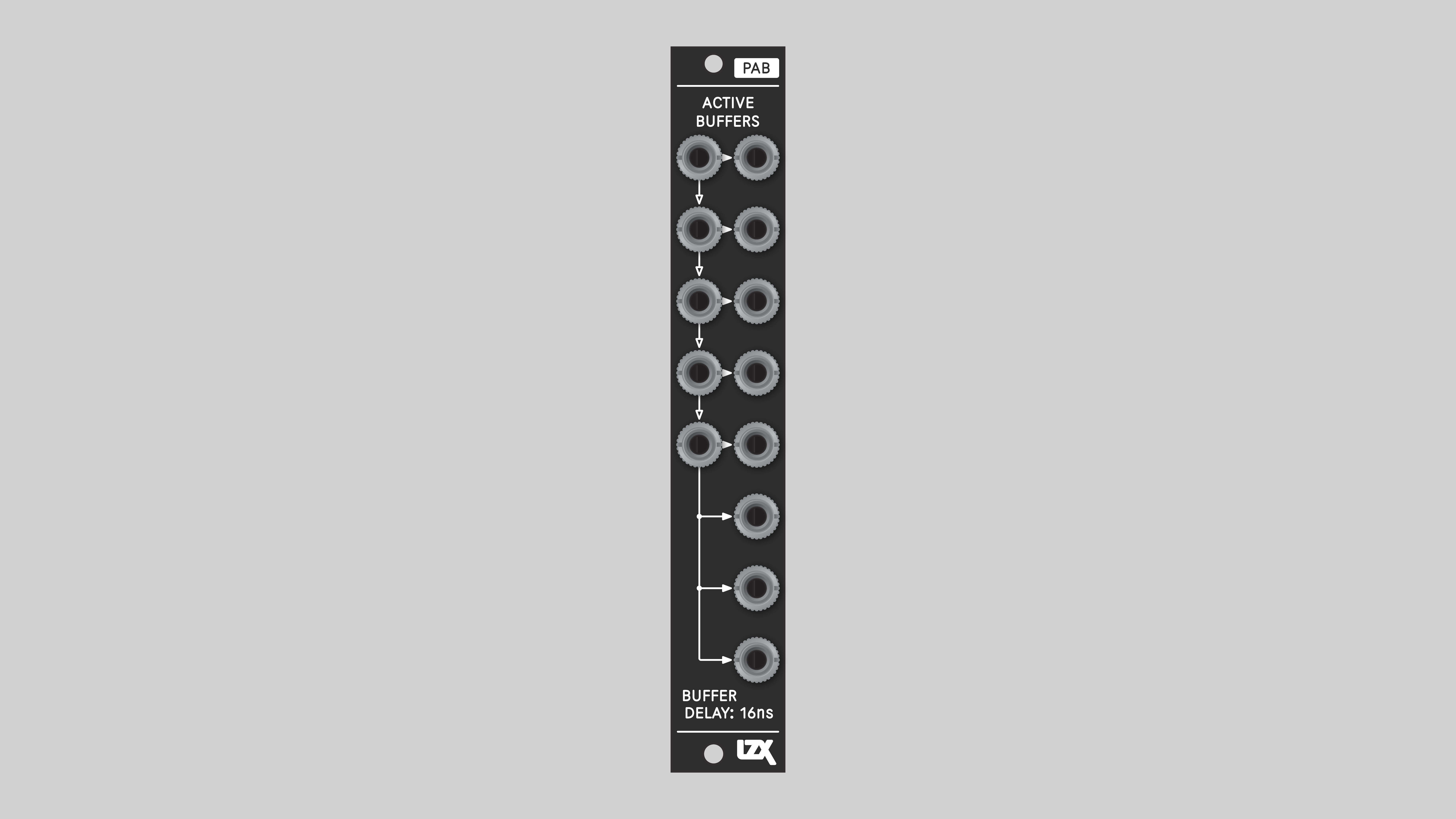
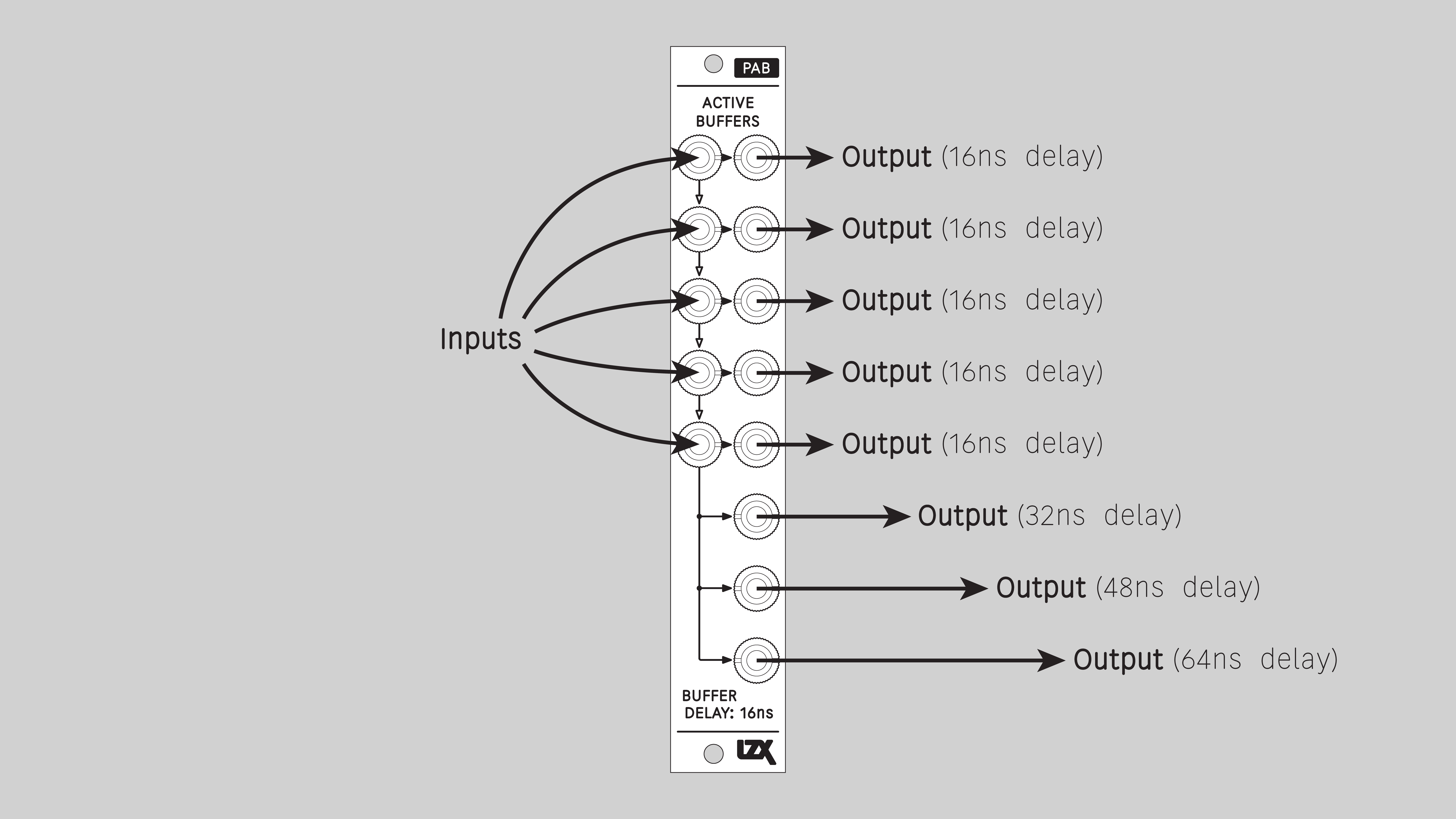
PAB is a utility for distributing and delaying signals. Duplicate a clean copy of a signal, or delay it in increments of 16 nanoseconds.
With delay times in the range of tens of nanoseconds, the result is an image shifted slightly to the right. Different modules delay signals by different amounts. In complex patches, this can be a problem. When signals are combined, they may be out of horizontal registration. PAB addresses this by inserting strategic delays to make everything line up.
Key Specifications
Mounting Width |
4 HP |
Power Consumption |
12V @ 50mA |
Power Connectors |
10 pin EuroRack ribbon, 2.1mm DC barrel |
Video Sync |
None |
Included |
DC barrel power cable, EuroRack power cable, red panel, green panel, blue panel |
Front Panel Options
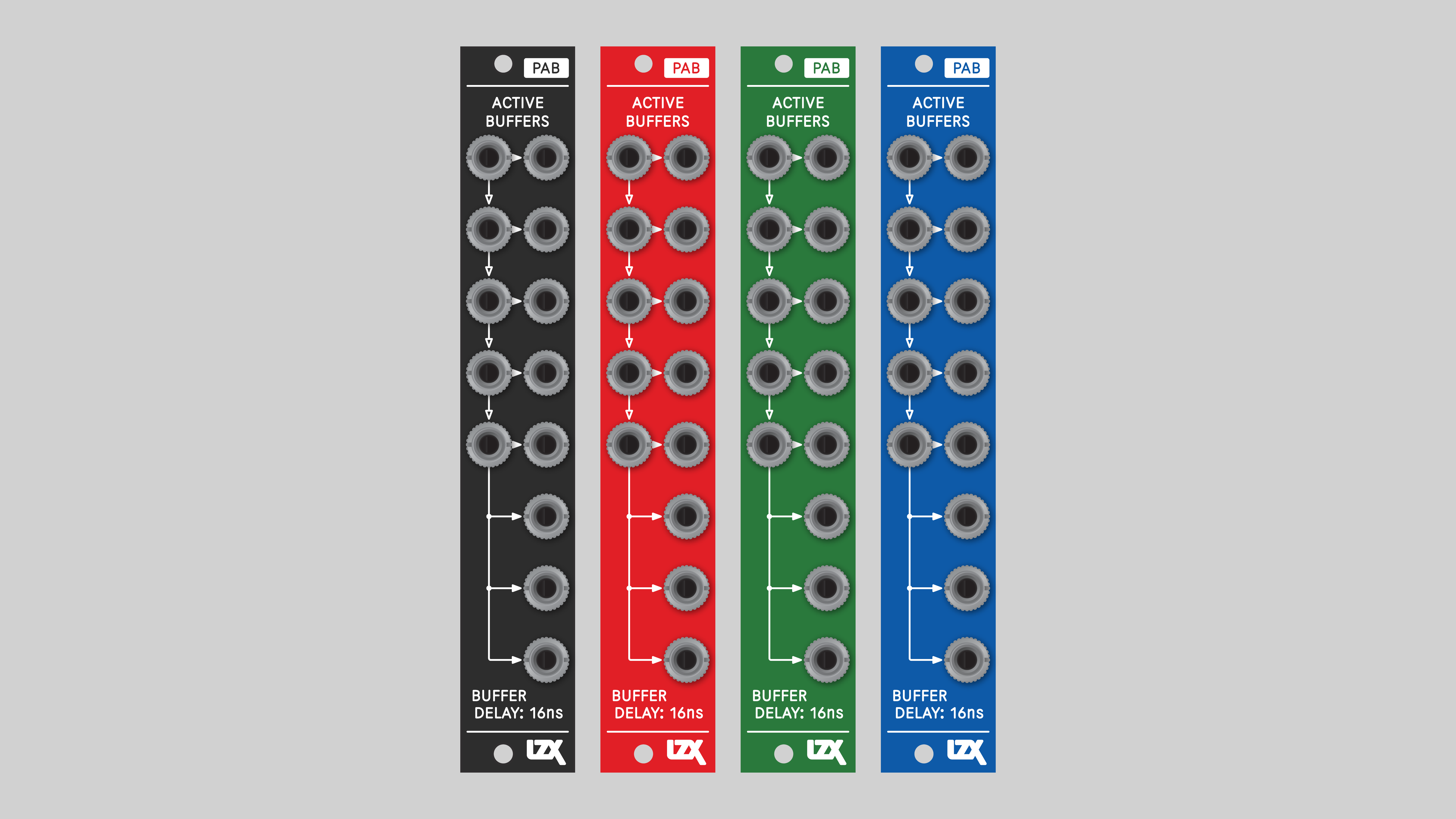
PAB ships with a black front panel installed. Red, green and blue panels are also included.
<!--
System Integration Advice
PAB is most helpful in larger systems with many modules, or if you’re concerned about horizontal shift. Even relatively simple patches may have registration issues with color components or compositing layers. This is most evident in high definition formats. For example, in standard definition, FKG3 performs an ideal self-key, where the foreground is the key source. But in high definition, the FKG3 self-key is out of registration by a couple of pixels. PAB is the fix for that: send the source RGB channels through PAB before FKG3, and the source luminance directly to FKG3’s external key input.
-→
Connectors
Understanding Cascading Input Jacks
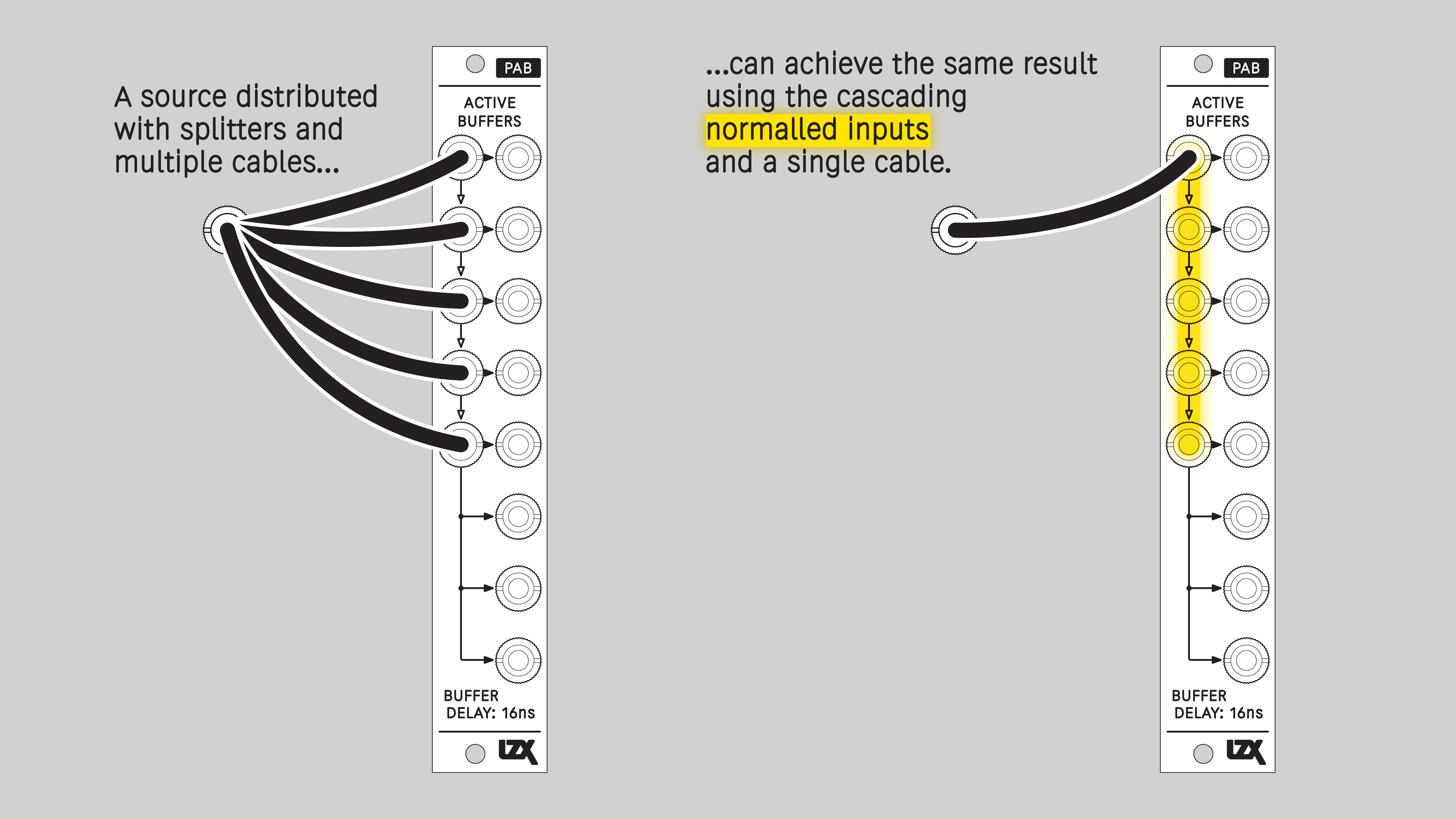
PAB uses switched, or normalled, connections between its input jacks. With no cable inserted, a signal flows down from one input jack to another. This connection is overridden when a cable is inserted. Normalled inputs are indicated on the front panel with arrows.
Installation
Requirements
-
EuroRack enclosure
-
12V DC or EuroRack power supply
-
2.1 mm DC barrel power cable or EuroRack power cable (both options included)
-
Eurorack power for PAB requires a 16-pin to 10-pin ribbon cable
-
Two M2.5 x 6mm mounting screws, or screws provided or specified by the enclosure manufacturer
-
#1 Phillips head screwdriver, or hand tool provided or specified by the enclosure manufacturer
Procedure
-
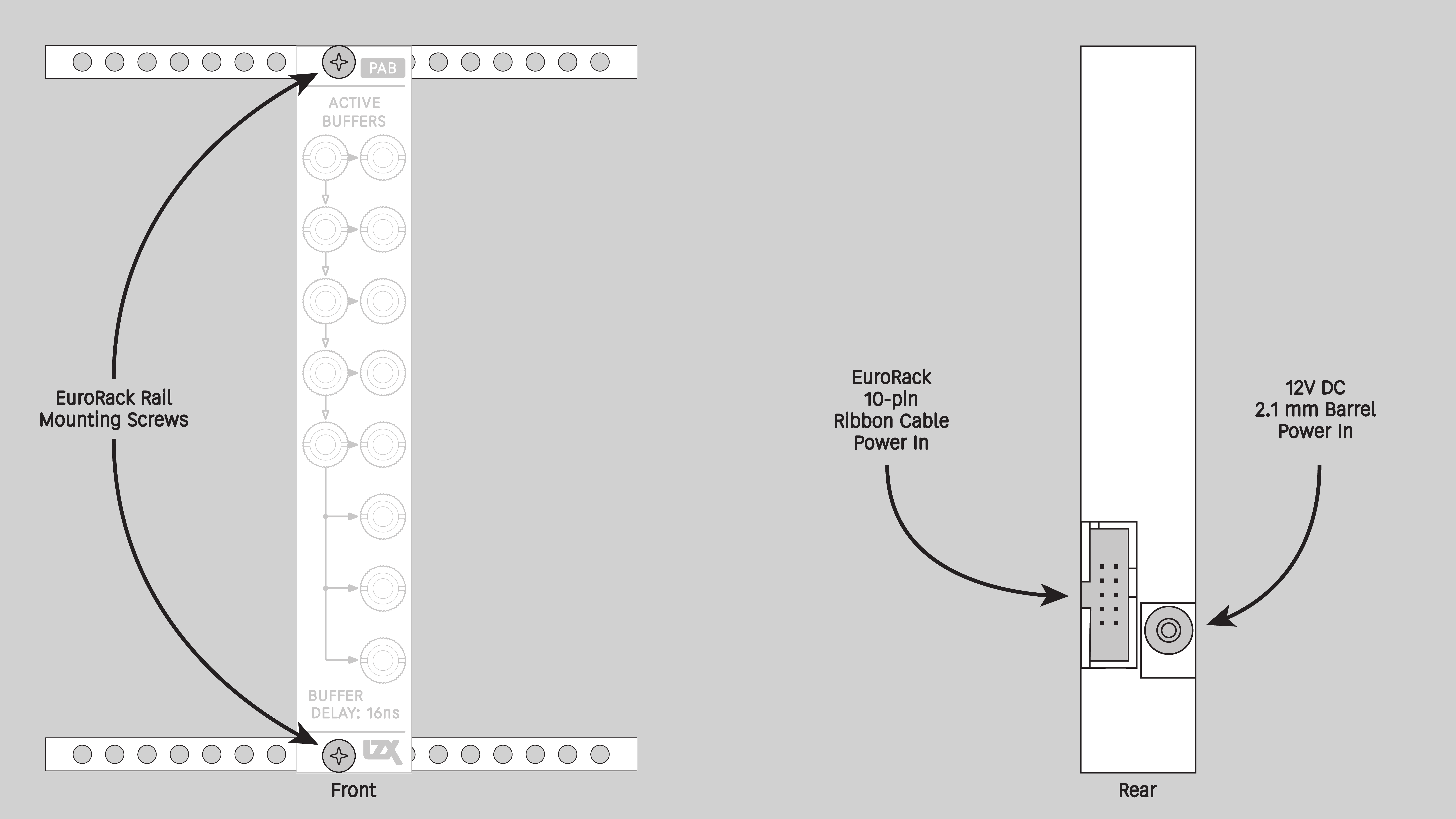
Power off and disconnect the EuroRack enclosure’s power supply and any attached DC adapters.
-
Connect either the EuroRack Power Cable or the DC Barrel Power Cable to the module. Do not connect both Eurorack and DC Barrel power.
-
Ensure that no mounting screws are in any holes in the area where you wish to mount the module.
-
Carefully test fit the module with its attached power cable in the open space in the EuroRack enclosure. If it is obstructed by the enclosure or any internal assemblies, abort this procedure.
-
Connect the disconnected end of the power cable to the power supply.
-
Mount the module to the EuroRack rails using all mounting holes.
-
Store the unused cable along with the product box in a safe location.
-
Power on the EuroRack enclosure and start patching.
Full Specifications
<!-- === Technical Data -→
Pronunciation |
pab |
Mounting Width |
4 HP |
Mounting Hole Count |
2 |
Power Consumption |
12V @ 50 mA |
Power Connectors |
10-pin EuroRack ribbon, 2.1mm DC barrel |
Input Impedance |
1M ohms |
Output Impedance |
75 ohms |
Input Protection Range |
+/-20V |
Input Clipping Range |
+/-2.5V |
Output Range |
+/-2.5V |
Propagation Delay |
16ns |
Module Width |
20.32 mm |
Module Height |
128.5 mm |
Product Box Width |
4 in / 101.6 mm |
Product Box Height |
2 in / 50.8 mm |
Product Box Depth |
6 in / 152.4 mm |
Included |
DC barrel power cable, EuroRack power cable, red panel, green panel, blue panel |
EuroRack Power Cable Type |
10-pin to 16-pin |
EuroRack Power Cable Length |
25 cm |
DC Barrel Power Cable Length |
25 cm |
RoHS Compliance |
Manufactured with lead-free processes |
Video Sync |
None |
<!--| Manufacturer Part Number | | -→ <!--| Mounting Depth | TODO mm | -→ <!--| Bandwidth @ -3dB | TODO | -→ <!--| Module Depth | TODO mm | -→ <!--| Product Weight | TODO | -→
Maintenance
Keep the module free of dust and debris by performing periodic cleaning. Spots may be cleaned from the frontpanel with a microfiber cloth and isopropyl alcohol or other electronics cleaner.
<!-- ## Troubleshooting -→
Hardware Revisions
The hardware revision code is printed on the circuit board visible from the rear of the module.
PAB-RevA
Initial prototype, January 2025
PAB-RevB
Initial production version, February 2025
pab_revb Schematic Diagram <br /> Download PDF
pab_revb Interactive Bill of Materials <br /> Download ZIP
DIY
Downloads for the complete schematic and an interactive HTML Bill of Materials are found in the Hardware Revisions section above.
Partial DIY Components
The partial DIY kit from LZX includes the printed circuit board and front panel. The following components must be purchased separately from electronics parts vendors.
| Manufacturer | Manufacturer Part Number | Description | Quantity | Reference Designators |
|---|---|---|---|---|
Wenzhou QingPu Electronics Co., Ltd |
WQP-WQP518MA |
3.5mm Jack Mono Switched |
13 |
J1, J2, J3, J4, J5, J6, J8, J9, J14, J15, J16, J17, J18 |
Pin Header Pitch 0.1in 2X5 Male Shrouded |
1 |
J12 |
||
Wurth Elektronik |
694106402002 |
DC Jack Vertical 2.1mm Barrel |
1 |
J13 |
Recom Technologies |
R-78K3.3-0.5 |
DC/DC Converter Submodule 3.3V |
1 |
U6 |
Assembly Instructions
This assembly job is recommended for intermediate level DIYers who are comfortable soldering thru hole joints in close proximity to surface mounted parts.
-
Mount and solder rear facing through hole parts first, in this order: pin header, DC/DC converter, DC barrel jack.
-
Mount and solder front facing jacks next.
-
Attach the front panel and secure it with mounting nuts for the jacks.
<!-- ## Functional Testing
The following tests are designed to verify the module is functioning as expected after assembly. If you are concerned your module is not operating properly, these tests may be used for self verification before a repair is initiated. It is also best practice to perform a functional test when selling or purchasing a module on the secondhand market.
Requirements
-
A voltmeter, multimeter or oscilloscope
-
12V power supply or EuroRack power supply
-
Patch cables
Setup
-
Connect the module to power and turn on your case
-
Prepare to probe the disconnected end of a patch cable — in these tests, the positive probe should make contact with the tip of the plug, and the negative probe or grounding clip should make contact with the sleeve of the plug
This concludes functional testing. If all steps starting with Verify… passed their conditions, the module is operating within expected parameters.
-→
<!-- == Performance Testing
The following tests are designed for verification of hardware revisions and general troubleshooting of performance issues. While intended for use by the LZX Industries design team, we publish the tests here to satisfy the curiosities of advanced users and service technicians.
Requirements
-
Oscilloscope.
-
Waveform generator.
-
2x BNC to 3.5mm patch cables.
-
Multimeter with probes.
-
Power supply capable of providing 12V DC @ 100mA.
Setup
-
Configure your power supply to provide 12 volts to a 2.1mm DC barrel connector.
-
Set power supply over current protection to 100mA.
-
Connect power to the device.
Test +3.3V rail accuracy
-
Use your multimeter to measure the voltage present at pin 3 of the U3 DC-DC converter module.
-
Verify that the measurement is within the range of 3.0V to 3.6V. -→