STACKER
Triple Window Key Generator
Overview
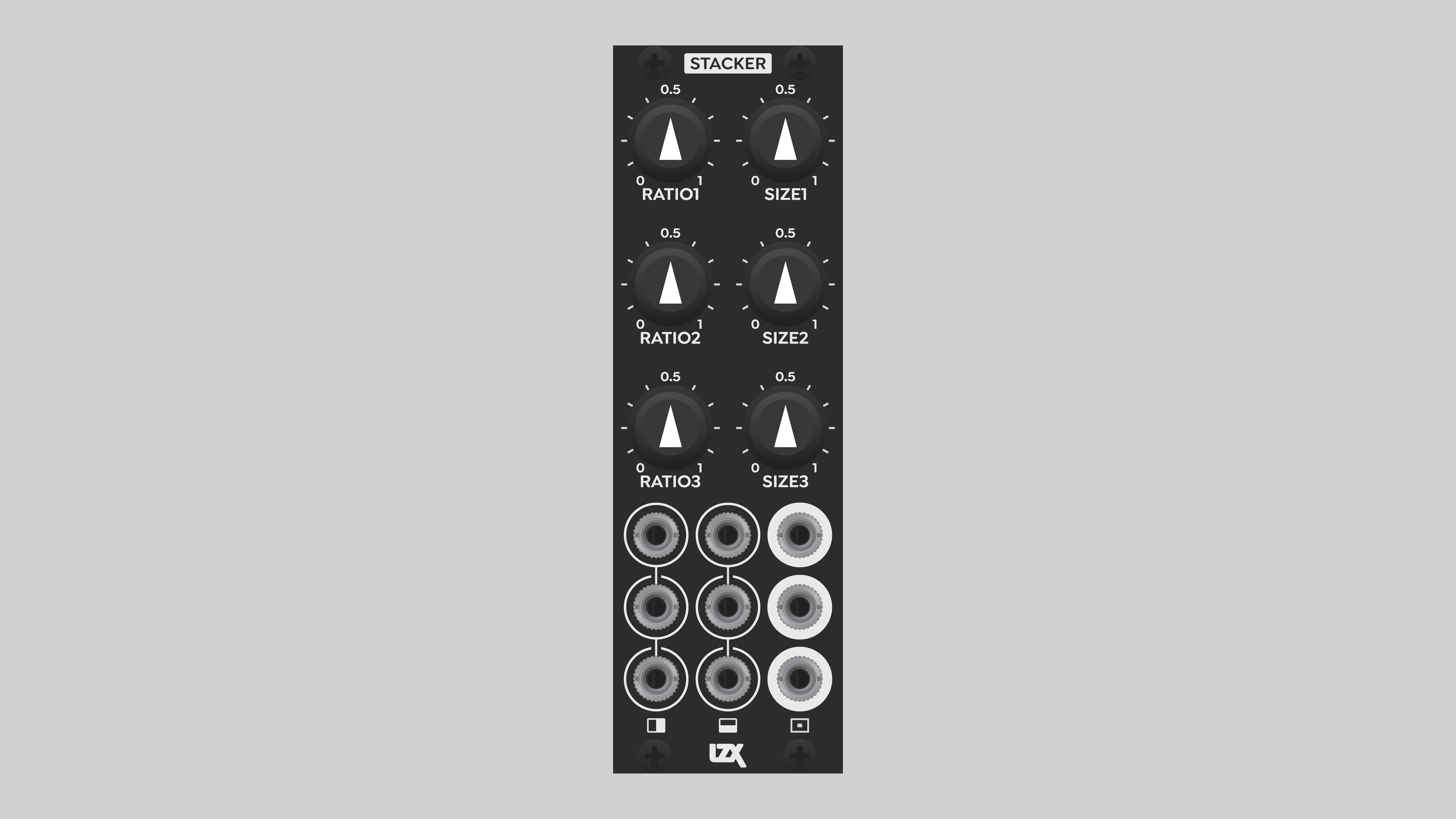
Stacker is a triple quadrilateral key generator and priority layer compositor. Its outputs are complex stacks of interlocking binary shapes that would require three cascading key busses on a conventional video mixer.
Here, the term "quadrilateral" doesn’t necessarily refer to four-sided figures. The shapes of the Stacker outputs are determined by the geometry of incoming signals. In this context, "quadrilateral" simply means that each channel has four cutoff thresholds.
Each Stacker channel has two inputs, nominally horizontal and vertical waveforms. Each input’s keyer has two thresholds, totaling four thresholds per channel. For a four-sided shape, these thresholds define the top, bottom, left, and right borders. Ratio and Size controls provide simultaneous, intuitive control of all four thresholds.
Each output is subtracted from the layers below it. This nesting doll effect results in non-overlapping key regions, or stacked priority layers. This has many creative applications, such as designing arbitrary shapes, e.g. letterforms and icons.
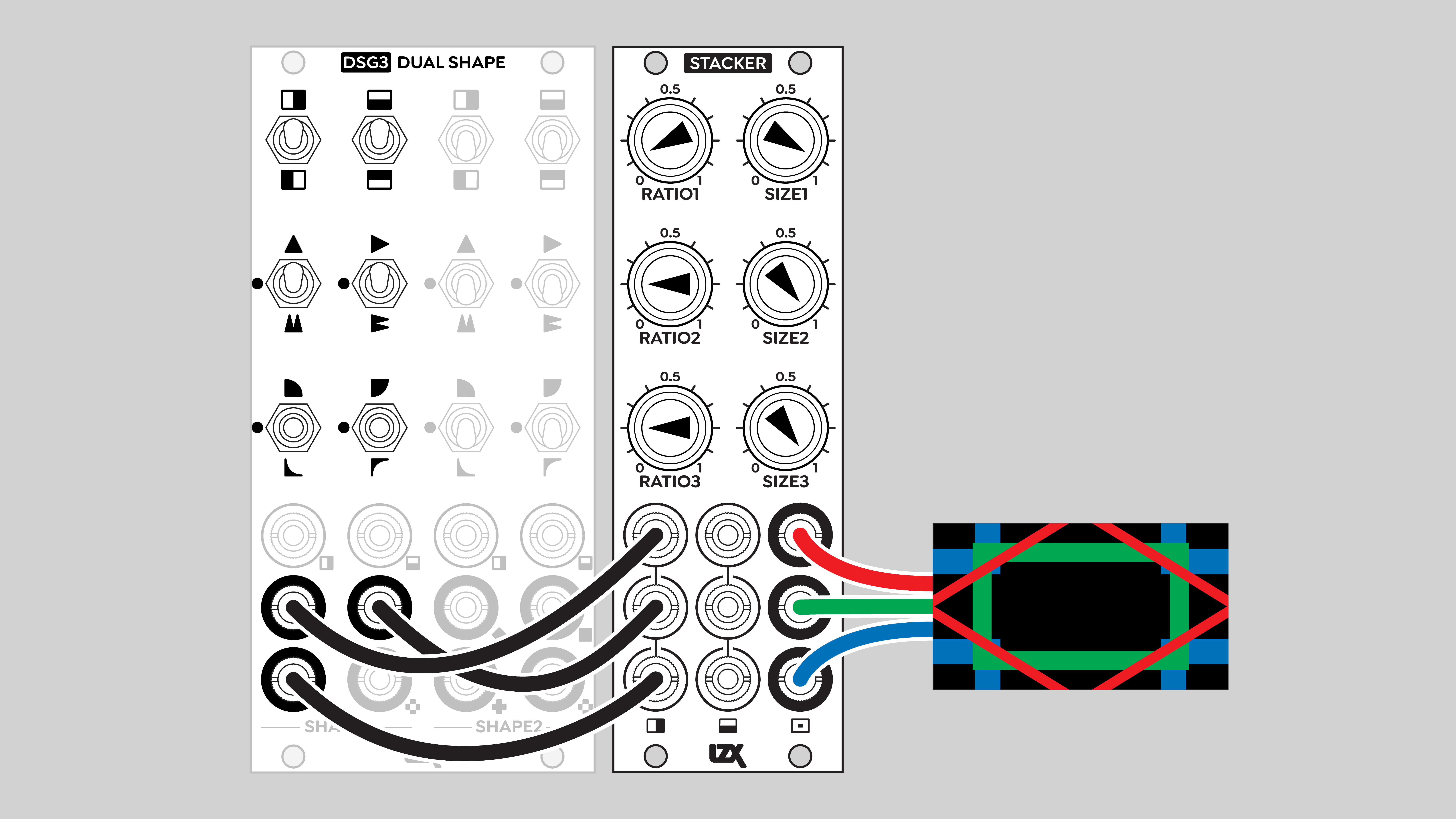
Pairs of complementary waveforms from DWO3, DSG3 or Angles result in three stacked, interlocking shapes. Or send complex images into Stacker to separate and composite different value ranges. Extract specific details from video images, gradients, precomposed patterns, etc. to construct more complex imagery.
Key Specifications
| Parameter | Value |
|---|---|
Mounting Width |
8 HP |
Power Consumption |
12V @ 95 mA |
Power Connectors |
16 pin EuroRack ribbon, 2.1mm DC barrel |
Video Sync |
None |
Included |
DC barrel power cable, EuroRack power cable |
System Integration Advice
Stacker’s outputs can be used directly, as a set of interlocking flat shapes. But Stacker’s full potential is realized in combination with other modules such as DSG3, SMX3, DWO3, and Proc. Stacker especially shines in complex pattern generation patches with multiple layers.
Controls & Connectors
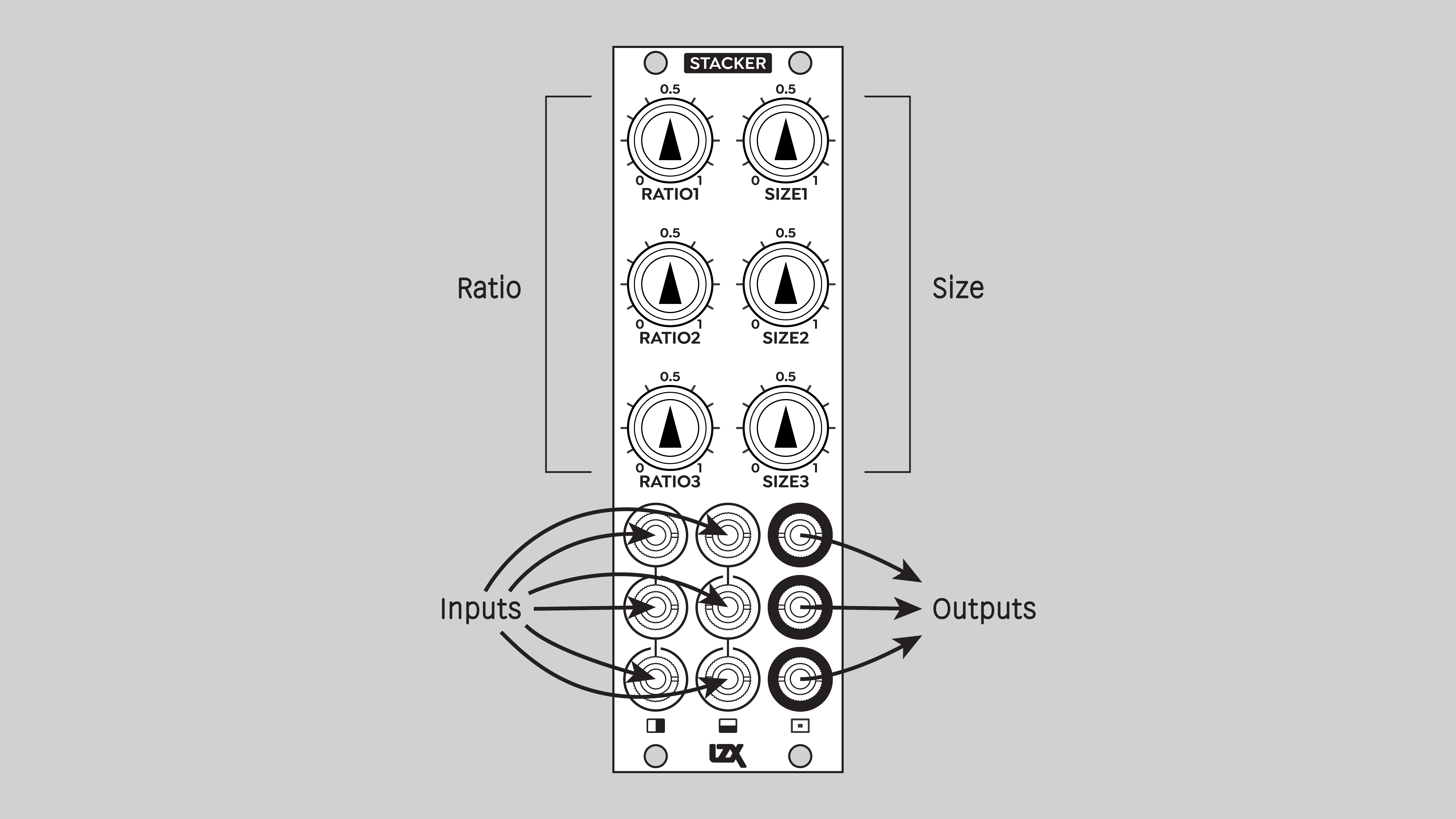
Stacker has independent three channels, 1, 2, and 3. Each channel has two inputs, H and V, indicated by horizontal and vertical icons. Just like DSG3, the inputs are labeled with the assumption of horizontal and vertical waveforms, but this is merely a suggestion. You can plug whatever you want into the inputs, including various gradients, video images, and low frequency control signals.
Each channel has two potentiometer knobs, Ratio and Size. These knobs provide quick and easy adjustment of the four thresholds of each channel’s window key generator. Ratio adjusts the shape of the window, Size adjusts the scale.
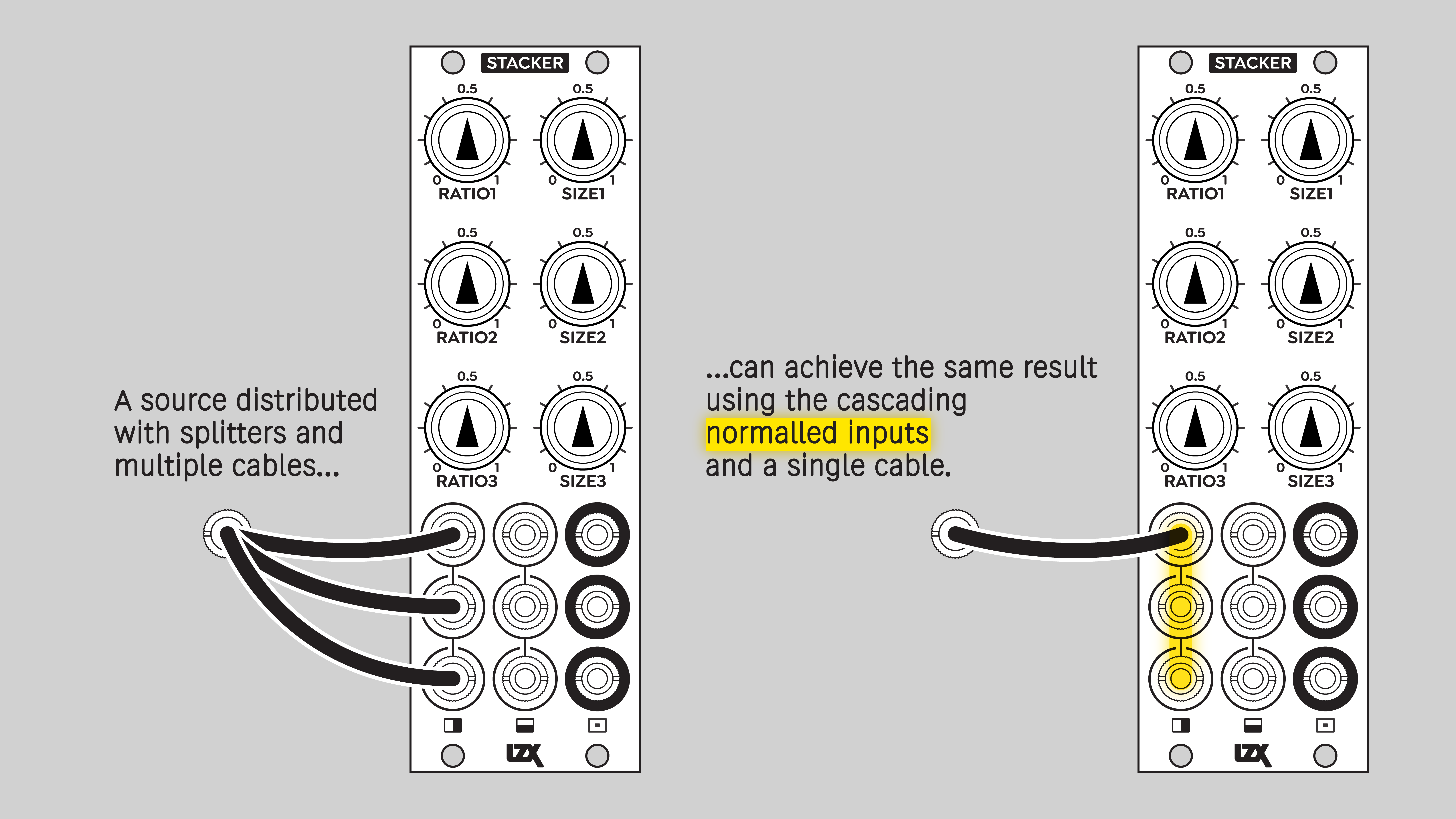
Each set of inputs is internally normalled in series from top to bottom. A signal sent to a top row input will flow to all three channels unless another signal is patched to interrupt the normalling.
Operation
Window Key
At its heart, Stacker is a complex multiple window key generator. A window key is a level up from an ordinary key. Whereas an ordinary key generator has a single threshold, a window key generator has two thresholds. Values below the low threshold and above the high threshold are clipped to zero, or black. Values between the two thresholds are rendered as white, or a value of +1 volt. That center range of values is the "window" that gives this type of key generator its name.
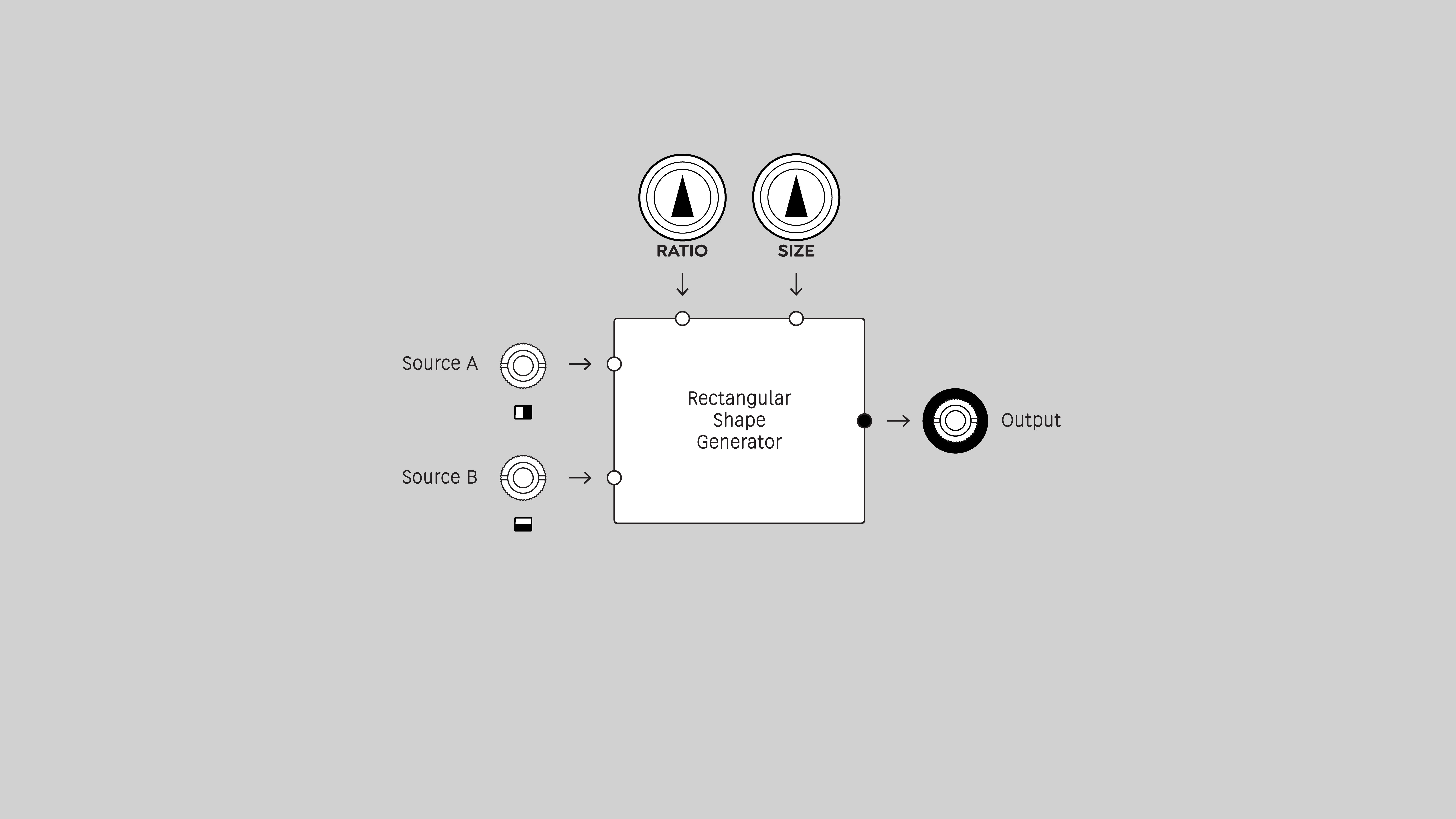
In the language of Stacker, the window key generator is known as a quadrilateral shape generator. That’s because Stacker is designed with rectangular 2D pattern generation in mind. But there is no limitation here; any video signals can be processed to give interesting binary shapes according to Stacker’s internal math.
Ratio and Size
Per channel, the H and V inputs are processed according to the states of the Ratio and Size potentiometers, resulting in an intersection of two window keys.
Both Ratio and Size knobs affect all four thresholds per channel. The adjustments are symmetrical, centered on a voltage of 0.5, or middle gray. For each input, the two threshold values are equally different from the center reference point. The high threshold is above 0.5 and the low threshold is below 0.5 by the same amount.
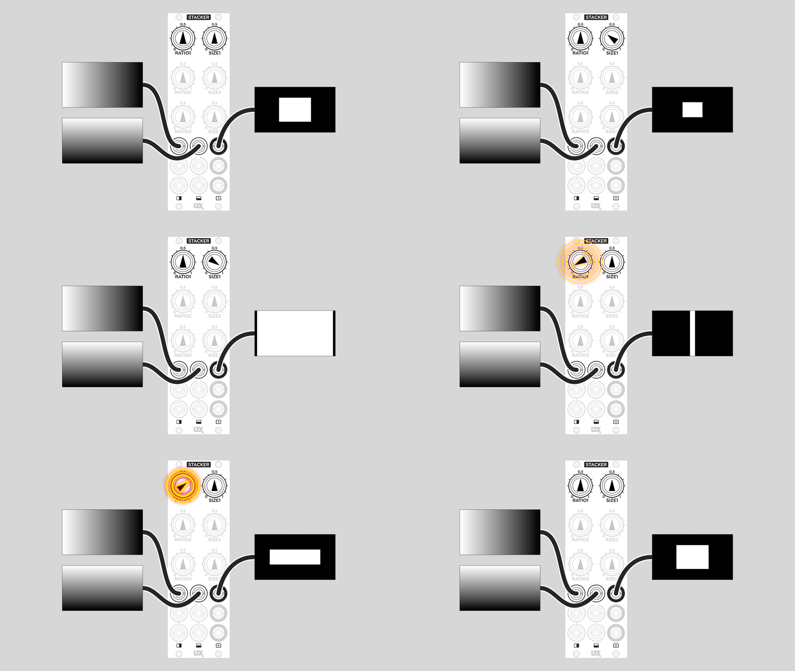
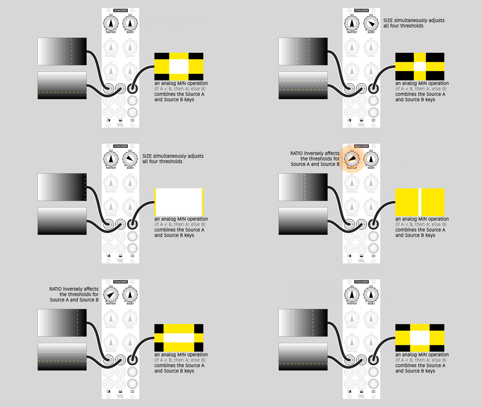
The Ratio knob adjusts the shape of the window. It sets thresholds for the two inputs in inverse proportion. As the H window size increases, the V window size decreases. This changes the window’s aspect ratio. At extreme settings, only one of the two inputs is applied.
The Size knob adjusts the thresholds for the two inputs equally. Both windows increase or decrease proportionally, according to the interaction with the Ratio parameter. This preserves the shape of the window.
Minimum / Logical AND
To create the full window, the results of the H and V window keys are composited with a mathematical Minimum operation. The lower of the two key values takes priority. Geometrically, this is the intersection, or overlapping area. And since the key signals are binary, this is also a Boolean logic AND operation. To output a value of one, both H and V keyers must have a value of one.
Note
Because the output of each channel is the minimum value of its H and V inputs, if nothing is patched into one of those inputs, the output will be black.
Layer Subtraction
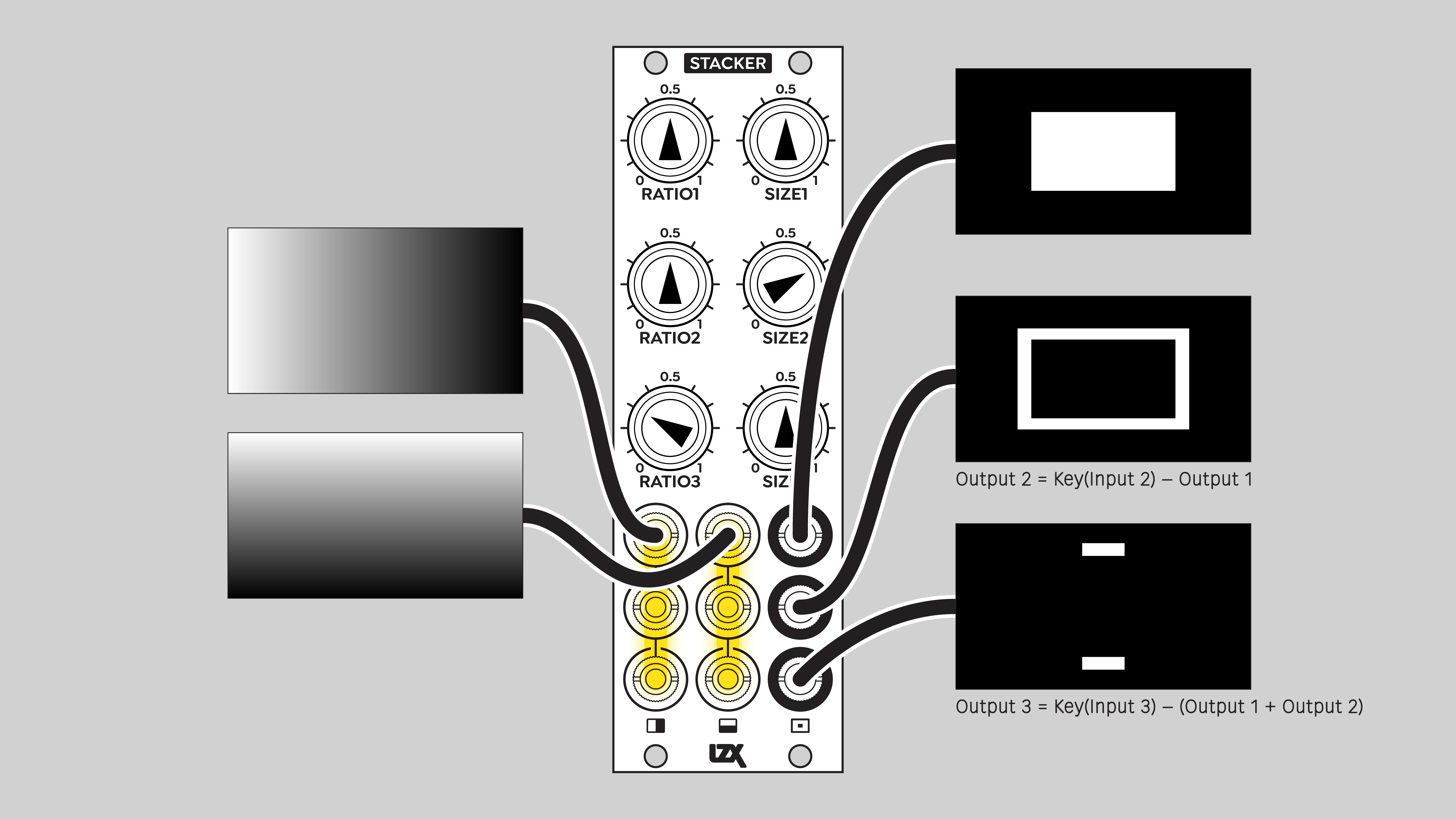
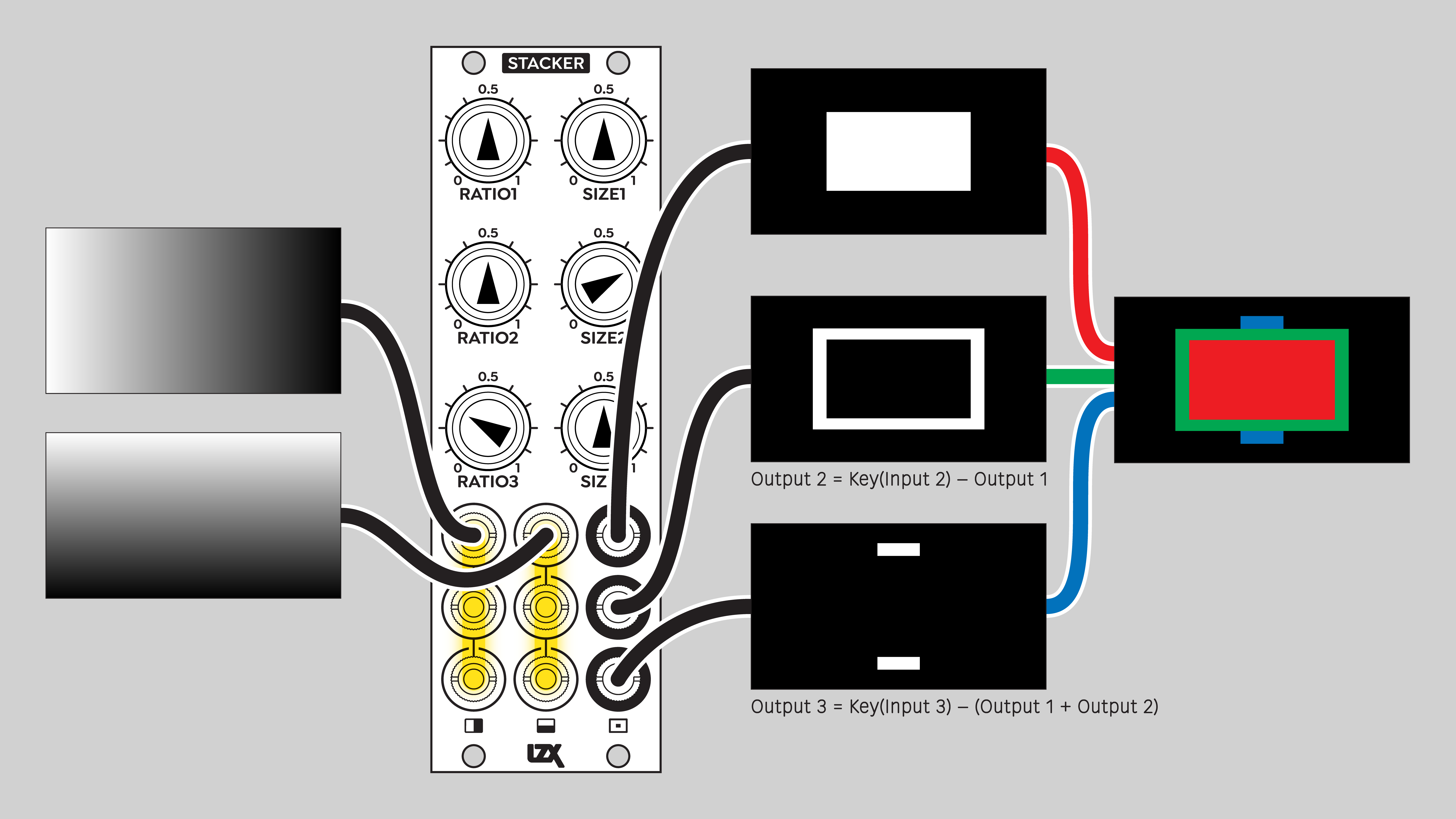
The channel outputs are also internally connected in series, from top to bottom. Each output subtracts the ones above it, resulting in complementary keys that "knock out" the other channels. The resulting shapes never overlap or blend in any way. Stacker is a multi-stage one-bit compositor, not a mixer.
Note
Like all video rate modules, Stacker is capable of processing low frequency signals. The simplest operation is a binary AND gate. Stacker’s subtractive layering can also be creatively applied to low frequency control signals, enabling interesting rhythmic effects such as skipping clock pulses.
Tip
If you’re not able to isolate the value range you want, then bias the signal up or down before sending it to Stacker. The ideal module for this is Proc.
Example Patches
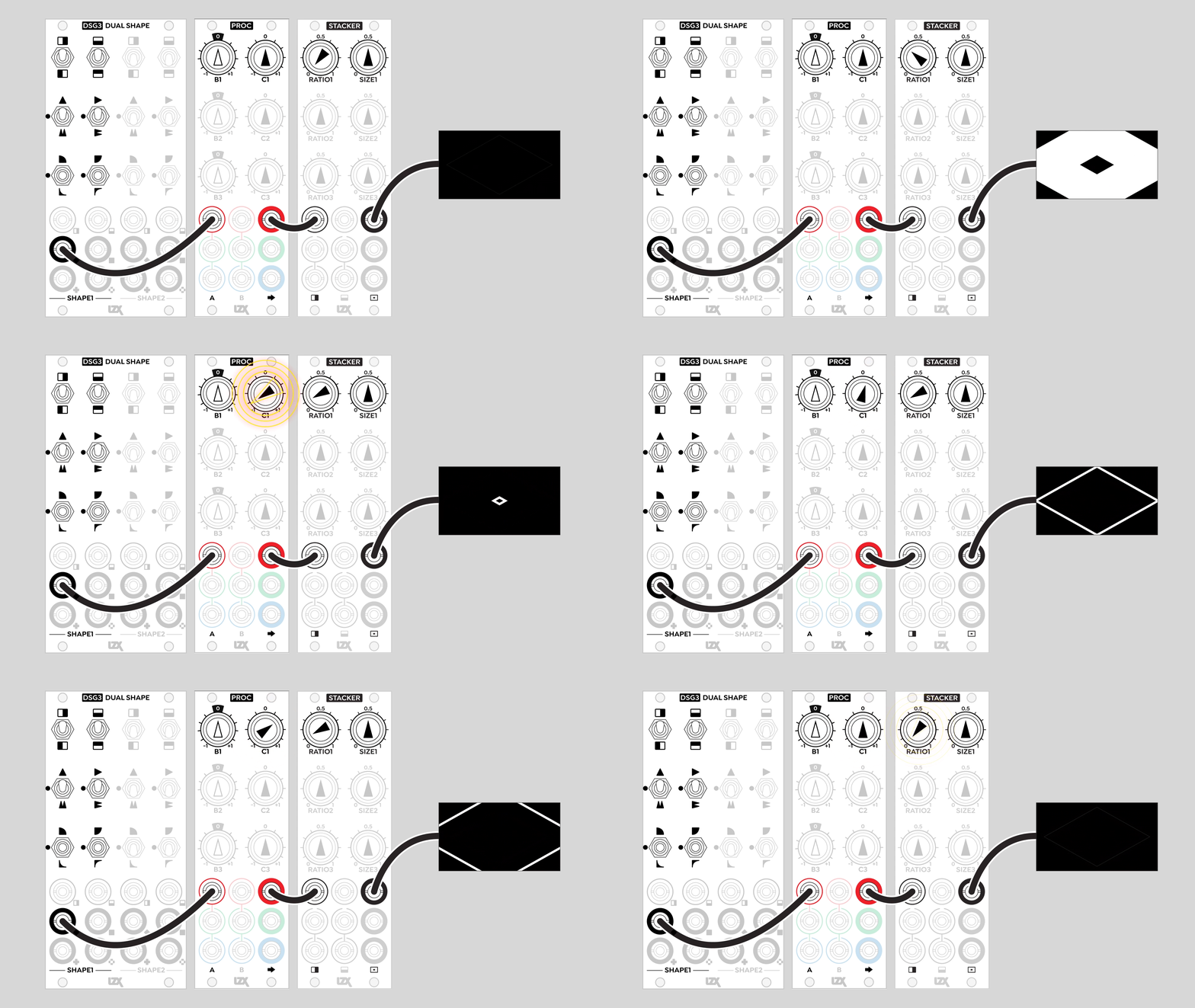
Priority Layering
Shape Outlines
Complementary Analog Logic
Installation
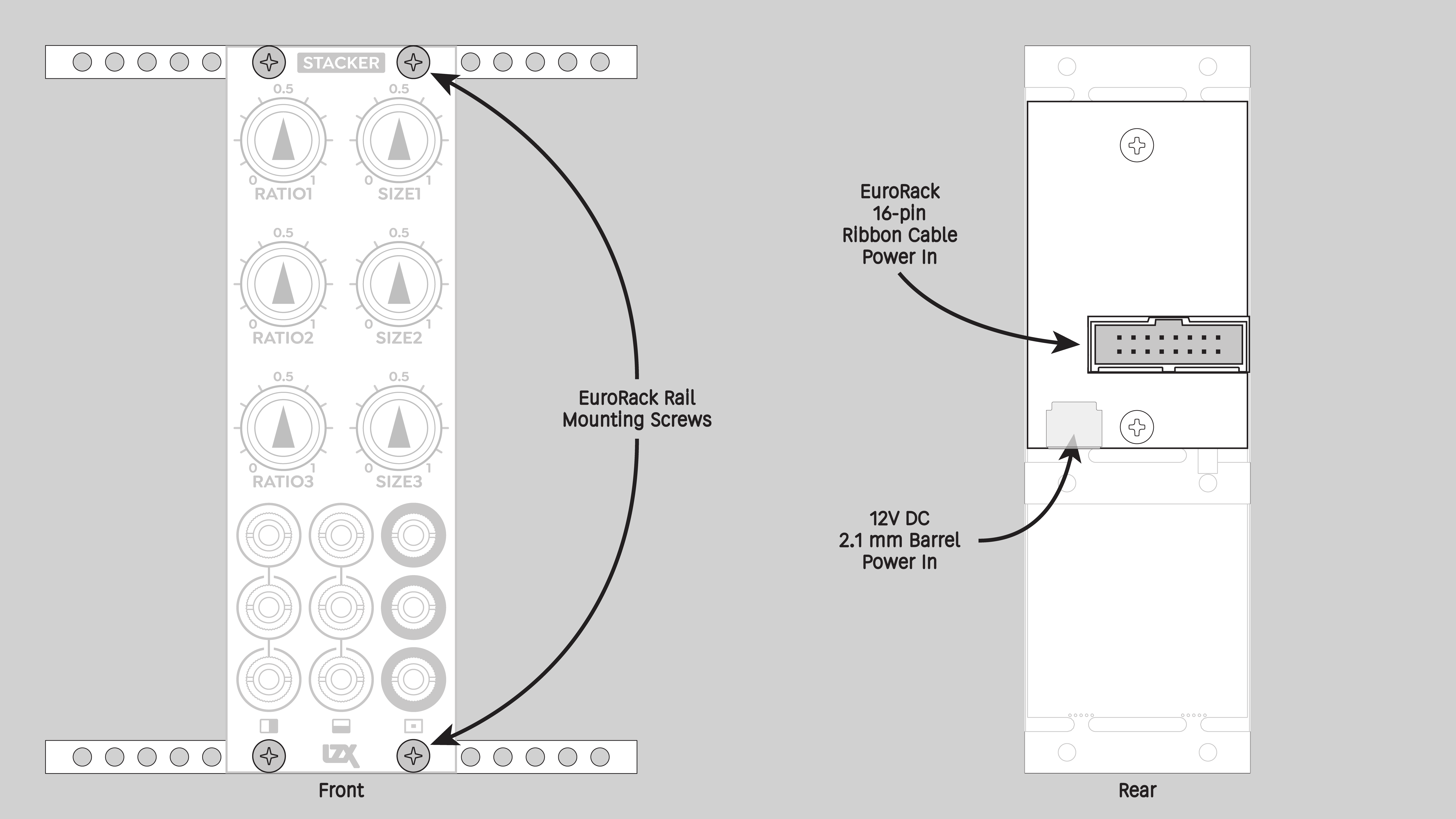
Requirements
-
EuroRack enclosure
-
12V DC or EuroRack power supply
-
2.1mm DC barrel power cable or a EuroRack power cable (both options included)
-
Four M2.5 x 6mm mounting screws, or screws provided or specified by the enclosure manufacturer
-
#1 Phillips head screwdriver, or hand tool provided or specified by the enclosure manufacturer
Procedure
-
Power off and disconnect the EuroRack enclosure’s power supply and any attached DC adapters.
-
Connect either the EuroRack Power Cable or the DC Barrel Power Cable to the module. Do not connect both Eurorack and DC Barrel power.
-
Ensure that no mounting screws are in any holes in the area where you wish to mount the module.
-
Carefully test fit the module with its attached power cable in the open space in the EuroRack enclosure. If it is obstructed by the enclosure or any internal assemblies, abort this procedure.
-
Connect the disconnected end of the power cable to the power supply.
-
Mount the module to the EuroRack rails using all mounting holes.
-
Store the unused cable along with the product box in a safe location.
-
Power on the EuroRack enclosure and start patching.
Full Specifications
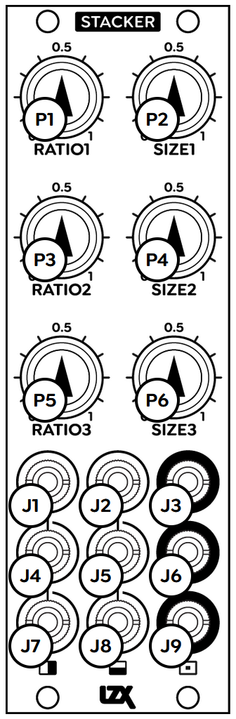
| Jack | Function |
|---|---|
J1 |
H1 in |
J2 |
V1 in |
J3 |
Channel 1 out |
J4 |
H2 in |
J5 |
V2 in |
J6 |
Channel 2 out |
J7 |
H3 in |
J8 |
B3 in |
J9 |
Channel 3 out |
| Potentiometer | Function |
|---|---|
P1 |
Ratio 1 |
P2 |
Size 1 |
P3 |
Ratio 2 |
P4 |
Size 2 |
P5 |
Ratio 3 |
P6 |
Size 3 |
Technical Data
| Parameter | Value |
|---|---|
Manufacturer Part Number |
950051 |
Mounting Width |
8 HP |
Mounting Depth |
32 mm |
Mounting Hole Count |
4 |
Power Consumption |
12V @ 95 mA |
Power Connectors |
16 pin EuroRack ribbon, 2.1mm DC barrel |
Input Impedance |
1M ohms |
Output Impedance |
75 ohms |
Input Protection Range |
+/-20V |
Input Clipping Range |
+/-2.5V |
Output Range |
+/-2.5V |
Included |
DC barrel power cable, EuroRack power cable |
EuroRack Power Cable Type |
16-pin |
EuroRack Power Cable Length |
25 cm |
DC Barrel Power Cable Length |
25 cm |
RoHS Compliance |
Manufactured with lead-free processes |
Video Sync |
None |
| Pronunciation | |
|---|---|
Propagation Delay |
TODO |
Bandwidth @ -3dB |
TODO |
Module Width |
TODO mm |
Module Height |
TODO mm |
Module Depth |
TODO mm |
Product Box Width |
TODO in / TODO mm |
Product Box Height |
TODO in / TODO mm |
Product Box Depth |
TODO in / TODO mm |
Product Weight |
TODO |
-→
Maintenance
Keep the module free of dust and debris by performing periodic cleaning. Spots may be cleaned from the front panel with a microfiber cloth and isopropyl alcohol or other electronics cleaner.
Hardware Revisions
The hardware revision code is printed on the circuit board visible from the rear of the module.