Visual Cortex Archive
Archived community reference. This page preserves the official LZX Community forum thread for Visual Cortex inside the new documentation site.
Additional related discussions are included below.

Core module with all required functions for EuroRack modular video synthesis.
- The Sync Generator section is a broadcast specification video sync generator which can operate in NTSC/480i or PAL/576i timing formats. It can provide the master timing reference for an entire video synthesizer system, and its timing may be synchronized to an external video source.
- Input Decoder is an analogue video input amplifier and colorspace converter. This section accepts YPbPr analogue component video, and processes it for patching internally inside a video synthesis system. The Y input can be used with Composite video signals if only grayscale operation is desired.
- Output Encoder section takes the output of the Colourizer & Compositor section, converting signals inside your video synthesizer into standard video signals which may be displayed and recorded.
- Animation & Key Generator is a multi-function control voltage generator, designed specifically for controlling transitions between two video images. It can function as a manual controller with slew, a flip-flop based envelope generator, or a low frequency oscillator. The key function enables a high-speed comparator, which generates a hard key image suitable for shape generation or luma keying.
- Colorizer & Compositor is a voltage controlled analogue video mixer. It features two RGB input channels, individual RGB controls and several advanced colour processing effects. We designed this section to be capable of addressing all the essential colour mixing required for a small to medium sized modular video synthesis system.
- Ramp Generator is a dual synchronized waveform generator. It generates grayscale gradients in horizontal and vertical outputs, with selectable output waveshapes. These signals provide the basis for many shape and pattern generation techniques.
- Visual Cortex contains many connectors accessible via the rear of the module. LZX Industries will not offer technical support or service for use of these headers, but savvy users may be able to tap into them and find them useful for custom applications.
Videos
Specifications
- Width, 26HP
- Mounting Depth, 45mm
- Power +12V @ 180mA
- Power -12V @ 220mA
Downloads
Other Resources
Thread Replies
Sharing the images linked below for fellow owners of v1, regarding rework and firmware updates!
(updated with more complete images)


Black level calibration instructions for this module should also be linked:
Related Archived Discussions
Visual Cortex pre-encoder expander
Soooooooooooooooo I’ve ordered a MemoryPalace and was thinking on how my workflow could be with it! And to be honest I would love to use the MP as final stage + encoder because of the HDMI outputs…
The problem if I do it this way, I won’t be able to use my Visual Cortex’s mixing+keying section (which I love and use a lot) , because cortex don’t have RGB LZX lvl outputs, so I can only use it as encoder final mixer… unless

I want to use the hidden treasures of the Cortex, pre-encoder expanders. So my plan is to build a small PCB of maybe 2hp or 4hp, that has the pre-encoder outputs of the mixer as a double buffered outputs (will be using those 6172 @pbalj that we purchased)
I wanted to share the idea to double check how feasible is, but also to know if any of you find it interesting, or if I’m missing something or a mistake).
With this expander, I can use VC super duper mixing capabilities and send it to the MP inputs!
Thread Replies
of course I would have to add 2 cables one 2x3 ribbon for the encoder output, and europower 2x5.
@pbalj maybe its a good idea for you 1u tiles
@luix did you end up building this? Has anyone else considered it? I might give it a shot this weekend (one set of outputs, without buffers, to start.)
For some reason, I thought the MP had a composite input, but I was sorely mistaken.
I’m not really a DIY guy, but I’d be willing to chip some $ in for the cause. This looks fairly simple though, so if it was a simple PCB, my shakey hands could probably solder it.
I have a composite to component adapter that has an RGB option, but I doubt it will work without some sort of attenuation to the 1v spec.
something like this? please correct any mistakes!
I’ve made 3 outputs now. Easy to double up if that is needed.
Maybe the buffers should be without resistors.? - pic2
(still a beginner)

or

Sorry for the super late response… I’ve been sick and bed the last week and couldn’t post anything.
The answering all of you, YES, I have a pcb design for this. Back in november I worked a bit on the breadboard and the crossed some conclussions with Lars on how to do this in the most interesting way.
The first approach was as @reverselandfill said just to use buffers, but Lars suggested to add attenuverters in the outputs to be able to invert the output signal of the cortex, also a LUMA OUT is super handy specially to patch in the alpha channel of the Memory Palace, here are some pics.


Here is the schematic, I’ll release the files on github once they are tested and working… It will be really bad if some VC die because of my fault 


Anyway, I’ll be building and testing these pcbs next week so expect some news soon!
On the second schematic you made, the R4, R10 and R14 are not needed. I made almost the same design and Lars said those resistors are not needed but the signals come from a known world (impedance, levels, etc…) the pins could go directly in the non-inverting inputs of the op-amps.
Yeah, I thought that already.
But good news with the progress. I’ll leave it to you then !
Where did the luma come from? is that a summed signal ?
Yes! Lars shared how to extract Lumma from RGB, using those magic weird value resistors.
aha magic. that was what I thought. I’ll check the schematic then 
Fantastic news, thank you! I was just thinking that a luma output would be a great use for the fourth op amp channel.
RGB to Luma is very handy (and a cheap addition!) Someone should do YUV to RGB and RGB to YUV boards at some point. If you had UV, you could patch up a chroma keyer with some Castle logic and some C8s!
For reference
From RGB to YUV
Y = 0.299R + 0.587G + 0.114B
U = 0.492 (B-Y)
V = 0.877 (R-Y)
It can also be represented as:
Y = 0.299R + 0.587G + 0.114B
U = -0.147R - 0.289G + 0.436B
V = 0.615R - 0.515G - 0.100B
From YUV to RGB
R = Y + 1.140V
G = Y - 0.395U - 0.581V
B = Y + 2.032U
So I finally pulled some time to build and test this pcbs, and the mixer section works pretty well… The problem I’m seeing is with the Lumma. I need to do further testing of the circuit.
For some reason when I put a signal into R it pops in all the other channels, the same happens for G and B, but there are not short or overlapped traces anywhere so Im guessing Im not testing it right.
I added some fast diodes to prevent voltage return to the mixer section on the Lumma resistors but its not working… maybe I need to connect all the three channels.


Anyway just a heads up on this. The schematic is already posted on this thread.
I need one of these for use with memory palace!
On the pcb, though, the 100nf decoupling caps should be as close to the power pins of the ICs as possible.
you are correct sir, thanks.
I think you may need to buffer the RGB inputs before putting them thru attenuverters, etc Can you probe what you’re seeing at the input nodes on the scope?
Apparently the problem was that I was testing with only one channel (R or G or B) at any given time, and the rest of the pins were “flying”. So the Luma resistors “mixer” made the signal comback from the other chanels the one connected/testing. This is not an ideal way of testing since all the time the VC will be connected and either send 0v-01v on each channel preventing this bleed.
I’ll add buffers to the inputs of the lumma and the before the attenuverters. If I only add buffers to the Attenuverters I will still get bleed from the Luma resistors-mixers. If I only add buffers to the 3 Lumma inputs I could get attenuverted signal from the feedback of path of each attenuverter.
So far the solution I like the most is to connect hte Lumma to the outputs of thf buffers RGB, that way there is no way to get it wrong. The only problem is that Lumma can get “dirty” if any cables with dirty signals (stacked) are plugged into the outputs of the expander.
Updates!
So I’ve worked a bit during the weekend on the pcb, now I moved all the 104 caps near the power pins of the 6172 as suggested by @pbalj, also added buffers to everything… I wanted to make this board very cheap thats was why I tried to save on ICs, but it doesn’t make sense to save up money just for 2 more 6172.


I’ll fab boards and panels and post back any news.

When the time comes and everything is finished, I’ll publish the eagle and gerber files probably in my github so anyone can fab it, in any case I’ll have spares that can sell… but was wondering if anyone is interested in kits maybe I can put together maybe 10 or so. If not I’ll only sell the pcb+panel set for like 10€ or 15€ depending on the cost of the aluminium panel :). Let me know your interest with for either pcbsets or kits?
I’d be in for the most complete version possible (no DIY skills here)!
love this project
I’d like a pcb/panel set please!!!
@wednesdayayay - watch a couple of basic videos on how to solder and then check out diy synth guy on youtube!
get a really basic soldering iron and a cheap kit to practice with (mults or something) - it’s really quite easy - I learnt last september and have built 20 modules - including 5 cadet and 6 castle modules and 3 smd (2 ripples and a buffered mult) virtually everything worked first or second time - one of the ripples is not quite right - but otherwise all ok
I’m interested in the kit if possible, but a pcb+panel would be appreciated as well. Thanks!
count me in for a Kit if possible as well!
I would take a pre-built or kit.
I’d be down for a prebuilt module!
I’d take a PCB + panel too, love the mock up :]
I could do a built module won’t be difficult, but keep in mind that you will need to mod your Visual Cortex, which is solder a 2x3 pin header.
Its not difficult but you will need to do it your self (or find someone close to you)


Yeah I’d be down for a prebuilt, Sure I could figure out fitting the header.
Hey, could a little header kit be sold w the modules? That would make things so easy!
the full kit im planning will have pcb panel, pots, knobs, jacks, components (ics, resistors caps etc) a 3x2 header for cortex and a ribbon cable for the rgb expander header.
@creatorlars Im gonna do a second flavor of the expansion with YUV outs. Was wondering if I can use the Lumma circuit that you kindly show me as the Y

or I must do another new lumma signal (I was going to go with voltage dividers of R G and B)
Y = 0.299R + 0.587G + 0.114B
My real question is if the Lumma of the YUV is different to the Luma schematic. Luma YUV vs Luma RGB (I would say no, but I’m in doubt.).
This lumma circuit is magix!
Great work on this @luix! I’m down for two kits. Curious as you’re planning a second breakout … could they easily be combined into one expander?
yeah should be easy to chain them.
@luix That circuit should work fine! For the U and V outputs you can follow a similar method. I generally use SPICE simulations to tweak circuits like this until output voltage readings are correct according to RGB input voltages. 5Spice has a free version we’ve used for years, although I’m using Tina more frequently now.
I’d be down for a kit to support the project. My cortex already has expansion headers soldered
I’ll probably want a PCB+panel at least. Wasn’t planning on getting a visual cortex, but I’ve run into a dead end trying to troubleshoot my cadet sync generator build–so I should probably just buy a vc.
Sign me up for one too!
I’ve been running the VC component output back into its Input Decoder, and then out from those 1v RGB outputs into the MemPal. Not so ideal, of course, as I lose that component input. :-/
I’d like to get a kit or prebuilt as well. This is a great project, thanks!
Def. in for a panel/pcb when you are ready to take orders
I am in for this! Would take a kit, or panel/PCB, or built version.
I’d be interested in panel+pcb or kit! YUV version would be great too - any chance to combine them, or will they be separate exapnders?
right! I would absolutely go for the dual if it was an option
I started to lay the PCB for the YUV version, but decide to first finish this run of pcbs test them, prepare kits, and a solder prebuilt modules and then will do the YUV.
Both will be compatible and can be used at the same time since they read from the RGB expansion bus of the Visual Cortex
Sounds absolutely reasonable. I am definitely still interested also in a single RGB version!
I’ve just got home and the postman had a surprise, and I remembered a quote from a famous American movie:
Life is like a box of pcbs and panels, you never know what your gonna get.
-Forest Gump

So final version pcbs (will double check them again everything is fine) and PANELS arrived.

This red panels are in honor to all LZX Cadets


@pbalj now caps are nicely placed, thanks for the suggestion I completely forgot about it.


Panels fit perfect on previous pcb (which is same footprint as the new one) there will be 2mm Red PCBPanel and 2mm Black aluminium panels. I don’t know if I should give the option to chose or just include both on every kit…
I still need to get to details to costs on kits and built modules, but will probably target at 50€-60€ for kits and 70€-90€ for built modules (plus shipping from Spain probably 6€-15€ depending if you are EMEA or Mericaaa). After all kits are sold I’ll sell spare pcbs :).
So my next steps will be to check everything is fine with the pcb, if so I’ll probably send a Google Form in this thread so all of you can write which ones and how many kits/modules you will want.
After the form is closed I’ll be able make the order of the parts to Mouser (so 3 days) and then I’ll ask you within those days to send me a PayPal.
Ill keep you all informed, I’m very excited on this project because its a community project for the LZX community. 
Updates on this, the board works as expexted, it as two minor bugs I’ll fix for the final version (pots are inverted, so positive signal should be from 12’ to 5’ (clockwise) and inverted signal from 12’ to 7’ (counterclockwise), second bug is that the color pins are swaped so Red is Blue and Blue is Red. in the video you can see how I patch a V ramp to the Byle and output that on the expander Red’s output.
One thing I wanted to ask on this thread for all your consideration and feedback is the following. When the attenuverter inverts the signal which is 0v to 1v DC from VC it outputs a 0v to -1 (inverted duh)… but the standard video signal is always 0v to 1v, so the inverted signal is not super usefull unless you use the AC switches or you invert it back or add a offset of 1v.
My question is, does it make sense and is useful for you to have an inverted (-1v) signal? Or should I replace the attenuverter with a attenuator (just attenuate from 0v to 1v and not invert). I’m scratching my head on which use case would be more useful for most ppl. I think there are use cases for both but what the vidiots think?
Maybe the best solution is to add 1v to the inveted signal, so its always 1V regardless if its inverted or not?
I’m asking all this for the first time when I actually plugged it and started to use it on different parts of my system.
It might be handy to have the inverted signal available for summing with a positive voltage. I don’t see much downside to using an attenuverter.
I’m def up for a kit or prebuilt, whichever. Ideally pre-built Really excited to combine the Cortex and MP like this. Thanks for your hard work!
I would be down with a prebuilt for sure!
Also in for prebuilt versions of both expanders when they’re available.
So I’ve been busy with another thing the last couple 2 weeks, but I think I will be able to finish the expander project in July. The current status is its a working version but with some noise, so I need to investigate whats the problem with the board.
This project wont get abandoned , anyway @pbalj told me he wanted to design/build/sell(?) another version of the expander he is probably working on so we may have 2 flavor of this expander soon!
I’m still very interested in a prebuilt unit!
at the same time
I like flavors
haha
I’m sure I’ll end up with a second visual cortex at some point that way I can do one of both
Ha! I am in the same boat. I am definitely getting a second VC in the future.
Im down for a prebuilt.
I am keen to order a pcb/ panel if possible , thanks
I´m also interested in an prebuilt one!!
greetings from sunny Bielefeld/Germany
Any news on this ? @pbalj ? I am interested in diy PCBs / or built modules for an output expander for visual cortex
Every time I patch my system, I miss this module. Wish I could help in some way, but I know very little about circuit design.
@creatorlars this could be a good idea for a new cadet module (diy pcb /panel), I feel like if more VC users knew what this does, it could be really popular
I’m happy to announce that the cortex expander is finally ready for production. I’ll post a vid later this week and all the details to order. Sorry for the big delays on this, but there were lots of things happening in my life lately but I’m back.
The plan is more less the following:
this week: I’ll send to fab the final pcb to China.
22-29/09 I’ll announce final cost and estimated shipping, a google form will be available to specify what you want. On 29 I’ll close the form and order components to the part supplier.
29/09 to 06/10 a friend and I’ll be soldering and building the prebuilt orders.
shipping is expected as soon each module is finished and tested, so first come first serve.
I’ll ship PCB+Panel only kits as soon the prebuilt modules shipping starts. I’m expecting this module to be very cheap hopefully. Anyway here is a link to a page we with some audio eurorack modules we have designed on the last years for local workshops in Madrid.

Hell yes. Thanks!!!
oh this is awesome
so if we do get a prebuilt unit this will still require us to solder onto the visual cortex itself right?
Is that 4hp or 6hp? I’m in the middle of rearranging my cases, so I’ll leave some room for it.
The RGB pads on the Visual Cortex don’t have a header in place for a connector, so a tiny bit of soldering will be necessary.
4hp, like a cadet/castle
Yeah I does, there is no other way as the VC does not come with pins on those pads as stated before. I’ll show later on before anyone places an order what you will need to do, just to make sure you know what you are getting into.
Its actually pretty easy, but you will need a good soldering iron, since the PCB of the VC has a superb thermal design and its difficult to heat everything.
I’ve done very very minimal soldering like point to point to make passive boxes (switches, photoresistors, pots etc…)
but after looking at the back of the visual cortex I think it is something I could handle
I am very much looking forward to this being available
if you can solder a wire to a pot then you can do this!!!
it’s as simple as sticking the header in the holes and then applying heat and solder - watch a youtube video first on the basics of pcb soldering and you’ll be good to go!!
I think the hardest part will be removing the panel and reattaching it!
It will be included, also all the cables and everything needed except the soldering iron and some solder and patience
that is so rad! this is going to make for some very fun video synthing
I’d like to get in on this for a board and panel.
I already soldered pins on to my corrtex and made an output expander to send RGB to the MemPal, but it’s not buffered at all, and your better solution is appealing.
Save two for me if I don’t respond immediately, it’s a busy time
It works exactly like that.
The luma is unaffected by the RGB knobs and goes out directly.
The RGB goes to a bit higher than 1v when the knobs are fully clockwise, and -1v when it goes counterclockwise.
On the middle (12’ clock) the gain is 0 and the channel will not pass thru. Hope that makes sense.
UPDATE! The pcbs are been fabbed now in china
Tomorrow I’ll record a vid on the module and publish the costs and form to reserve a module. I’m planning on doing a 30 built run, and 30 pcb set, with some spares
Here is a vid I recorded to try to clear what I think is important.
TBH the only thing I dont like about this module is that potentiometers are too tight (close) so I sacrified some ergonomics in favor of having luma outs plus as-much-as-possible skiff friendly module.
It looks awesome! Ready to order 
Nice video and great work @luix!
@luix How do I order one diy panel and pcb. Thanks 

Please DM me for payment
IDGI why it needs 5x lm6172 ? Don’t they 2 channel on each chip
You have to buffer each input (3), each output (4), so you’re looking at 7 opamps minimum, or 4 LM6172’s. I guess you also need some for the luma mixer, too?
@joem is correct, the signals need gain in this case so they need to be amplified as well. I breadboarded a single channel similar circuit few years back and it would have used 6 LM6172’s (my memory’s hazy - no input buffer, inverting amp and inverting output buffer I think).
More updates on this, PCB from factory came and I built it.
I’m noticing some bleed noise on channels when doing the “hard edge” test that Lars always recommend to detect bleed, otherwise the board is good to go. I wrote to Lars and Phil to see if anything can be done to remove/reduce this.
This means maybe two more weeks of delays so you all start ordering yours. I don’t want to ship you a board that has some noise (even if is small) and I’ll end up refunding paying stuff so just want to be super honest and clear with what you will be getting… I will record a clip explain this hard edge test, and showing the bleed so you all know a little bit more on how you should test your video equipment/commands.
What’s a little noise on a hard edge! Standing by, @luix…
I feel a little stupid here, so please excuse the noob question!
Can anyone explain, simply, why I might want to do this with my Visual Cortex? I’ve read through the thread here, but I can’t get a grasp on what this upgrade might be used for, in practical terms?
this gives your visual cortex LZX standard 1/8 outputs of whatever is coming out at the composite/svid/component outs
RGB and LUMA
this could be used for feedback, further processing connecting to another system lots of fun stuff!
So we’re not placing orders yet right? Don’t want to miss this when it’s time!
Im waiting for final PCBS with ground plane to reduce bleed noise, they have been manufactured and their are on their way to me so should be receiving them next week probably.
One use case would be if you have another module with its own set of video outputs and you want to feed it a signal that’s mixing both of the Visual Cortex’s compositing channels together. Some LZX modules have RGB 1v outs (Color Chords, Marble Index, Mapper, Memory Palace), just as the Visual Cortex has two sets of RGB ins in its compositing section.
However, the only way you could get full RGB (or the functional equivalent, at least) out of a Visual Cortex without any sort of expansion attached is via the component outputs. BUT, in order to put this back into another part of the LZX system, it would need to be decoded again via another Visual Cortex input decoder section or a TBC module, as it is now a valid video signal instead of the LZX 1v standard. This expansion panel serves as a much less cluttered way to continue processing a fully patched Visual Cortex, or to take advantage of final output via another module (such as the DVI/HDMI output of the Memory Palace).
Did that help? 
Thanks Tylerm, that’s very clear explanation.
I guess I’ll join the queue for this awesome upgrade!
Finally got my expander installed and it’s working great! This thing kicks ass with memory palace
Great to hear that enjoy it
yeah no turning back
it really made the chromagnon make more sense
that was I think one of the last straws for me before pre ordering (getting this up and running)
It’s like have an entirely new flavor of feedback for memory palace. Wonderful!
Thank you so much for this @luix it’s amazing!
I can’t believe that it’s taken me this long to get around to building it!
The only thing that I would advise is that if you use a shrouded, keyed header, then it will overhang the PCB a little bit. This makes it a little bit to fat to fit between Doepfer type rails. I desoldered it and put a pin header on, instead.
As you mentioned, the PCB ground plane makes desoldering difficult.
Great news!!! so let me know if I can do anything for you or share any patch ideas
every time i used this expander it makes me more excited for chromagnon
things are going to get wild
is it normal that all my knobs are at about ~75% turned to pass through the regular colors?
I guess my expectation was that it would be at 50% but I could just be misunderstanding something
this has always been the case since I got it from you but I never really mess with the knobs so I forgot until the other day when I was re setting up my system
Following this because I’m a bit unsure on that too!
Yessss I specifically designed the circuits so they have about 120% gain when full clockwise or counterclockwise (inverted), I found I wanted to have extra “saturation” on my output signals sometime and that extra 20% worked fine. The downside of this is you will have to dial in the unity gain which has not been a problem for me really but well doesnt have to work for everytone as it works for me
12:00 > zero gain
3:00 > 100%
4:30 > 120%
9:00 > -100% (inverted)
7:30 > -120% (inverted)
Nice Expander, @luix! If one would forego the RGB pots, how hard would it be to just put the RGBY jacks right on a Visual Cortex, so as to save HP and keep my panels consistent looking?
I dont think its possible the VisualCortex panel is full. Unless you do an extreme mod an desolder the RCAs for components out or the composite outs and then drill, or something like that but I really dont recommend you doing so…
Oh! That’s a good idea, @luix
If there’s a way to squeeze in a toggle switch, one could add RGB option to the component out RCA jacks.
Or, the same amount of panel real estate would fit a mini jack to accomodate a triple mini to RCA adapter http://tinkersphere.com/raspberry-pi-accessories/523-raspberry-pi-a-plus-b-plus-composite-to-rca-adapter.html
Where can I order one of these?!
try dm’ing luix - he may have some left - may only be a kit or a pcb/panel set though
I checked today and I have 2 prebuilt and lots of pcbs so whatever you prefer.
Hoping to buy one too, PM’d as well!
Is there a website I can purchase through?
I’m interested in one of each of the PCBs!!!
Are there any PCBs/kits still available? If so where can I order?
Hi everyone!
I’m very sorry that I have not answered before any messages, but I was unaware of all of them for some reason I don’t get notifications on my email when someone PMs (I have to double check the notifications configuration on my account).
I still have pcb+panel sets if anyone is interested! Price is the same (in euros) please just note that snail mail to the US takes a lot of time now, some orders have taken probably 3 weeks and others almost 7-8 weeks but in the end all of them arrived safely.
If you want to get a set, just drop me a message to hadesbox at gmail dot com.
Sick! Just emailed you
I know @cinema.av (Evan Henry) was trying to get ahold of you - did y’all get in contact?
Yeah I just answer him today, need to hear back from him
Per the book of faces (which I look at approx. once a month or so), apparently @pbalj has a VC expander module.


a little different with no knobs but negative outs of everything included instead
so neat to see more stuff coming out from PB well not THAT PB…
@wednesdayayay I see what you did there you ciat head
Have messaged Luix, are you still shipping?
would love one too if still possible 
Since some have asked about availability, Teleos Modular in Columbia, SC has one cortex expander left, last I checked. He has a reverb shop.
Not anymore… Sorry (not sorry)
Haha, nice, I got my order in before posting.
For those still interested, I noticed Teleos Modular listed more for sale today. I’m not affiliated with his shop, but I’ve picked up a few things from him and he’s a really cool guy. The build quality of the expander is excellent, technically and asthetically.
thx for the ups still have five built expanders available if anyone is interested & i can sell for $140 shipped in the US if bought direct instead of via Reverb. send me a message or email if you want one!

VC expansion header install failed - that or the module is bad. Took my time, but having a heck of a time getting the contacts hot enough to get the solder flowing. Using a Hakko digital soldering station at 700F with Kester 245 63/37 no-clean solder.
On a brighter note, I modded my ER-301 Rev 7 so that it could talk I2C to my F8R faderbank. I thought that would be harder - had to solder a resistor lead to bypass an SMT diode. But the VC header is proving to be more difficult.
Repeat after me - You love to solder, you are a worthy, patient person who loves to solder. I don’t think the affirmation is working. 

I don’t have any direct help with the actual issue, but when troubleshooting something like this, it’s a good idea to keep your signal chain as minimal as possible. Forget about the Color Chords for now. Instead test straight with “Prismatic Ray → Memory Palace” and “Prismatic Ray → Visual Cortext & Expander → Memory Palace” (and make the VC Expander → MP connection just be a single channel, not all three).
Doing that reduces the variables and reduces the likelihood of accidentally connecting something wrong or forgetting to connect something. (And makes it easier for other people to help you out for the same reasons.)
Did you build the Expander yourself or did you just solder the 6 pin header to your VC?
I don’t have a VC but I’ve seen the drawing for the expander module. Maybe your 6-pin header is flipped 180 degrees. Three of the pins are RGB luma and three are ground so it is possible that luma and ground are all switched.
Lets have a look at your 6-pin ribbon cable between the VC and Expander.
Yes, that is good advice. I was only using the Color Chords to demonstrate that the Memory Palace 1V RGB inputs were working, to rule the Memory Palace out as the issue.
The Visual Cortex does not have front panel 1V outs (like the Color Chords), but does have them on the circuit board. That’s what the 3rd party expander is for, though it requires the soldering of a header on the VC board for a ribbon cable to the expander.
But I can test one at a time, but even if one of them were working and the others weren’t, I would expect some change of output on the display.
I didn’t build the expander or the ribbon cable, but I did solder the header. My hunch is that is where the problem lies.
I can hook it up to a scope and see if there is output from each channel.
Thanks for your help!
I bought the module prebuilt from the creator in one of the first batches over a year ago, but only got around to soldering the header this weekend when redoing my cases. He also provided the cable (and header)
I was careful to lineup the little triangle on the header with the R channel, so the indentation in the shrouded header is facing outward in this case.
I’ll pull it out again tomorrow and take a look at it and get some photos.
Thanks for your help!
Hola @northerntao Josh, I’m very very sorry for the problems you are facing, its very weird but possible that the module I sent you is broken. I personally tested each “built” module for at least 30mins on my Cortex, precisely to avoid all these problems with all the people that got the expander. I wanted to avoid hassles to ship it back etc.
Anyway can you please take out the module and send some hires pictures to my mail hadesbox at gmail (or post them here for other future users, whatever you prefer) of solder joints on the expander header in the VCortex and also of the module (both sides) to see if there is any obvious soldering problem on the module?
If you want to ship the module back its also an option so I can check it out whatever you prefer.
If you want to test the expander “standalone” without the cortex, and you can do simple soldering I recommend you building this board with 3 minijacks and a 3x2 header for testing the module. Its a super simple board that I built for testing each Expander before actually plugin it to my system, with it you can directly input 3 signals and test the three channel attenuations to discard if there is a problem with the module.

I just remembered another user that had similar problems, and it was because I shipped him a “too short” cable and when he plugged the expander and put it back to its case, the header cable was unplugged by all the wiggling of the module during the module installation on his case.
The cable should be just enough to connect it, the very first cables I made were super short to avoid noise because the longer an unshielded cable, its more probable it becomes antenna for noise.
Hey @luix! Thanks for the response! I’ve had a busy week with work and life so I haven’t had a chance to look at this again. Hopefully tonight.
The case its in is kinda cramped with cables so it may be the cable is loose. I’ll try that first. If not I’ll try removing and redoing the solder joints with a bit more heat on my iron. It took a lot longer than I’m used to to get the solder to melt.
@luix - typing this on a phone and this forum editor hides the typing after a couple paragraphs.
So I’ll try that and maybe a different solder and flux. I’m using the no-clean Kester solder which has worked fine for me in the past, but I’m not a big DIYer.
If that doesn’t work I’ll let you know. I have some breadboard and various components laying around.
I know its been a long time since you shipped the module - I appreciate your help after all this time
@luix Hey Luix! By any chance, do you still got any VC Expander PCB + Panel available? I’m looking for one. Thanks!
I have the kit, but not the 6-pin header for the back of the Visual Cortex. I keep buying headers but the pin spacing doesn’t match the points on the back of the Visual Cortex. What spacing am I looking for? 3mm? 2.54mm? 2mm? Maybe some LZX folks can advise.
Here’s an extract from the BOM - quoting Mouser part numbers for 2.54mm spacing header
| Type | Value/Description | Qty | Part Number | Notes |
|---|---|---|---|---|
| Pin Header | 2x3 PIN HEADER | 2 | 710-61200621621 | Expander connector |
| Pin Header | IDC 2x3 connector | 2 | 649-71600-006LF | ribbon cable connector for expander |
10 pcs. 2.54mm 2x3 Pin 6 Pin Straight Male Shrouded PCB Box Header IDC Socket Amazon.com
Any standard 2.54mm double pin header should work, then you just strip it to 2x3.
Should I start out with Visual Cortex, Vidiot or the DIY Cadet modules?
Should I start my video synthesis journey with Vidiot or with Visual Cortex? What would you recommend for a beginner just getting started? We’d love to hear everyone’s opinions, this is a question we are often asked.
Thread Replies
There is a third option: Cadet series!
Yes! This post came from a migrated question. I’ve edited the OP.
Hello -
I’m totally new to video synthesis but have been lurking for some time and am interested in getting started. I am already invested in eurorack for audio so I’m steering toward commands. That being said, I’m into DIY and am interested in the Cadet series but am also ignorant as its capabilities and what I would want/need as a starting point there.
Any help is much appreciated! Apologies if there is a more appropriate post for my specific inquiry. Thanks!
When I was a beginner (with modular video that is) , I started out with the Cadet 21 set (21 pcb’s)
The Cadet modules only have a BOM and the schematic,
and you have to source your own parts.
I did this before, so that was no obstacle for me.
It was a lot of work (everything custom, so a lot of wiring) but it became a very nice system.
I grew quite confident of my DIY video module building skills.
I’m now adding new modules to my system that are build from schematic (LZX has quite a few cool documents on their site: a summing mixer,a VCA, Sandin designs and all Cadet and Castle modules are available as schematic too.)
This route has enabled me (as a not so wealthy video artist) to create a large video system with extensive possibilities.
Thanks LZX!
I’d recommend this route to all die-hard DIYers :)
brand new to video synthesis and I started with Vidiot. For me it was immediately fun, I was up and patching right away but still referred to the manual when needed.
I own a eurorack modular synthesizer and I’ve been using lumen, processing and praxis_live for video for quite a while for processing video, creating ad modulating shapes and webcam feedback, with mixing, layering etc.
I’m thinking about adding an old video camera, a 2nd macbook (both of which I already have) and possibly a video mixer and to start integrating hardware video synths…
so should I dump the mixer and get a system made up of visual cortex, prismatic ray, color chords, staircase and a couple of bridges and maybe add a memory palace and a diver (and obviously other modules) in the future
or should I get the mixer and a vidiot and just be done with it? and spend the money on audio modules!!!
@Agawell It’s hard to say, it really just depends on how much the LZX style modular workflow suits your creative personality and the kind of content you want to create. There are always surprises and new perceptions that happen after you start actually patching. What you can do with the modules you described vs. a video mixer + Vidiot is vastly different and the modules certainly take you into some territory that’s hard replicate otherwise. But Vidiot is essentially a module inside its own case, too, so you could expand from that instead of starting with Cortex (any of the modules that don’t require sync are great for this… Pendulum, Staircase, Doorway, etc.) I would just find a spot to dip your toe in, and then grow in the direction you find most interesting.
To answer the OP’s question, Visual Cortex, Vidiot, and the DIY Cadet modules all have their strengths and weaknesses as starting points, IMO. Here’s my attempt at listing the ones I can think of…
Visual Cortex strengths:
- a lot of utility packed in
- excellent base to expand from – if you’re planning on getting more LZX modules, you’ll soon realize that this is practically a necessity
- really well designed module
Visual Cortex weaknesses:
- price – the most expensive of these options, it might be too pricey as a first video module for some, especially if they don’t already have a eurorack case to put it in
- can’t do a whole lot on its own – not to say it can’t do anything, but it really shines as the input/output/glue for other modules
- needs eurorack case and power
Vidiot strengths:
- can do a ton of things out of the box! – you could potentially be happy with this alone
- can interact with LZX modules (and other people’s modules too) – expansion is totally possible
- don’t need a eurorack case or power supply
- easily portable
- the most immediately fun of all these choices
Vidiot weaknesses:
- kind of pricey – for what it does, it’s an amazing price! but like the VC, it might be too pricey for a beginner dipping their toes in
- I don’t think I can see any other weaknesses???
DIY Cadet modules strengths:
- easy DIY builds – through-hole and low part counts puts these way on the easier side of DIY builds (easier than most audio modules I’ve seen!)
- the least expensive option, for basic synthesis – with just Cadet 1, Cadet 2, and then something else (Cadet 4 or 9, probably) you can start synthesizing some video, though it probably won’t be terribly exciting
- many of the Cadet (and Castle!) modules are great additions to the retail LZX modules (and Vidiot)
- the Cadet modules are basic building blocks of video synthesis – you can learn about the basics before moving on to the other more complicated (but excellently designed) LZX products
- the schematics are freely available – great for learning purposes, but it also means it makes modifying them easier
DIY Cadet modules weaknesses:
- you have to build them – not a problem for everyone, but a roadblock for some
- you have to source the parts yourself – again, not a problem for everyone, but a roadblock for some
- not as immediately fun as the other options – they’re basic blocks, so you need a whole bunch of them to even approach what the other options are capable of
- needs eurorack case and power
One notable strength for ALL of these options:
- Lars is amazingly generous with answering questions and helping people out – there are a lot of helpful creators in the modular world, but Lars is seriously at or near the very top of the pile!
(I just realized this’ll need to get expanded to add Memory Palace, too, but I’m not going to add it yet since it’s not even released and I don’t have the best grasp of what it does yet.)
I started with some Cadet modules, since I didn’t really know much about video synthesis at all and wanted to dip my toes in slowly and on the cheap, and I’m pretty proficient with DIY commands. I still haven’t moved beyond LZX’s DIY offerings (so grain of salt with my pros/cons above!), but I now have more Cadets and some Castle modules, and I’ve learned so much about it all. I didn’t really understand what a lot of the Expedition series did, but now that I’ve played around with a lot of Cadet stuff and learned more about video synthesis, I get it, and I really appreciate their designs. (Seriously, Lars, awesome stuff!) Next time I’ve got money to make big modular purchases, I plan on getting some.
If I were getting into video synthesis with the level of understanding I have now, I’d probably get a Visual Cortex and some other modules (if I could afford that) or a Vidiot (if I couldn’t afford the VC,etc). But I regret nothing about my Cadet and Castle modules! Almost all of them will be great companions for when I do start getting Expedition series stuff, and I’ve had so much fun with them so far and probably wouldn’t have figured things out as much as I have without them.
Really thoughtful and useful post!
@reverselandfill @joem Thank you both.
Am I correct in understanding that the cadet series modules come with a blank pcb/schematic (and panel) that I need to layout and route myself? Or is the PCB routed and the schematic provided just as a engineering/reference/learning tool. I’m pretty sold already, I just want to be sure about what I’m getting into 
The Cadet modules come with blank PCBs and frontpanels. You need to buy all the parts yourself. The schematic is provided for learning/reference, but you can also just install the parts according to the BOM without ever looking at the schematic. If you haven’t done electronics DIY kits before, I’d recommend you get a kit that comes along with step-by-step instructions on how to solder, source parts, etc before diving into these, which are intended more as intermediate/advanced level projects for the electronics hobbyist.
It takes 11 Cadet modules to begin to approach what Visual Cortex can do (probably around the same for Vidiot), so Visual Cortex and Vidiot are definitely the better “bang for your buck and time” purchases, unless DIY is just something you’re excited and passionate about. With video synthesis there’s an up front kind of buy-in cost of all the host I/O circuitry, and you have to pay that no matter which approach you’re going. Think of it like buying the DAW/Mixer combo for an audio rig – those items are necessary in order to start recording and mixing tracks.
In my personal opinion, the best approaches for people on a limited budget who aren’t too scared of Synth DIY, would be Visual Cortex plus a few of the Cadets that expand it well (C9, C6, C7, C8 especially) or if you want more of an encapsulated instrument, Vidiot plus a couple LZX Expedition modules in a small Euro case (Passage, Staircase, Pendulum are all good for this.)
Vidiot goes a long way, but if using it without other modules, prepare to invest in a nice camera/feedback setup, as that’s where it really shines and you get the most out of it. If you’ve already got some video mixers and cameras, then it’s a great way to step in and incorporate this stuff in your rig without feeling like you have to keep buying modules if it’s not something you want to pursue further.
If you’re on a very extreme budget or just love DIY stuff, Cadet only can work… it’s just going to be a lot of modules before you feel like you’ve got a complex system. I just want to make clear that it’s tempting to consider Cadet to be the cheapest route – but if overall budget is the concern, and a complex system (rather than just a starting point) is the goal, most of these options tend to even themselves out at the end of the day.
@alargeformat “blank pcb’s” / The pcb’s are not blank as in perfboard They are routed and printed.
The schematic is for reference.
The Cadet route is very ‘open’, in a way that everything is patchable, and must be patched to get things going.
This means that you will need to understand every module very good and use several modules for basic synthesis.
The Cortex & Expedition modules have a lot of handy routings and features build in.
These functions can also be patched with the Cadet modules, but this will take more effort.
(input and output attenuverters, waveform options etc)
I have a panel that combines the sync generator, the video input and the output encoder.
Most of my other panels are dual or triple (like dual VCO’s, dual Processors, triple function generators)
You can combine several Cadet modules in one custom panel to save some patch cables ,
for example: a VCO and a Processor & Multiplier in one package. That’s one option I’m considering now
Maybe that route is for the more experienced builders. Start with a few Cadets and work from there!
Hi, as a complete beginner I really appreciate all the info thus far.
Ultimately my main interest is effects processing. Sending external video (and maybe audio) in, manipulating it, and then recording the output (not for live performance).
How much of a stand alone unit will Memory Palace be?
If it is, can anyone recommend a basic 2-4 module set-up for that? Would you need Visual Cortex at all?
Of course, I’d love to start big with the modules above, but I’m still unsure if the Vidiot can do a fair amount of effects processing as well? Most of the examples I see are more colored shape and pattern generation stuff. (I guess you could just add a video source and it might be more of what I’m looking for???)
Can anyone help me better wrap my head around the possibilities?
Thanks much.
@vacuum Memory Palace is not meant to be used as a standalone unit – generally when we do EuroRack modules, the design decisions relate to the context of a larger system (we have a pretty expansive vision of how it all fits together.) That said, you could do an effects processing system with just the TBC2 + Memory Palace that would be awesome and do a wide range of effects, especially if you have lots of external modulation options. This may be the best approach if processing and a small initial system is your goal. You will need TBC2 to get external video into the system’s patchable workflow, and then Memory Palace provides all the effects and dedicated video outs.
If you’re into the more analog processing techniques like colorization, solarization, RGB and wipe offsets, etc Visual Cortex by itself goes a long way as a processor as well. Vidiot can process external stuff but you can’t get full color video through it from in-to-out, and it’s best in a feedback loop environment with external cameras and video mixers.
Great question, and people have given very thoughtful objective insights. When I think about this question of how to enter the world of video synthesis… I find myself thinking about what I would have done different if I knew what I know now, or in light of the latest gear that is available. My take on it is predictably very personal, but… If I were starting fresh now. I’d start with a Vidiot, hands down! … except that the waiting list is a major stall out if you want to get going ASAP.
Background:
My start was with a 3TrinsRGB+1c… on a whim… half purchased with a tax return. I was very aware of LZX equipment at that point, but I didn’t know what I was doing and couldn’t justify the entry point cost. I explored the 3Trins for a short while before I hit a creative wall. I then started tinkering with DIY circuits that I could power from the 3Trins and interface on the header pins… in order to expand on the 3Trins and also utilize it as an RGB encoder for video circuit experiments. It was exactly the slippery slope I feared it might be (hoped for?).
Eventually I purchased a Visual Cortex, originally to have a more flexible platform for encoding and experimenting… one that was much more advanced and robust than the 3Trins. After that I saved up for a Staircase, Bridge, and Video Logic. Those are my only LZX modules so far, but I love them. I am waiting on a Vidiot, and I look forward to the day I can play with it!
All that said… if I were starting over… I would dive in at the Vidiot point for the following main reasons: [1] it is a “ready to play” system (similar to how 3Trins was for me), and that is a great way to have fun right off the bat; [2] it effectively represents (to me) a best blend of benefits between something like a 3Trins and a visual Cortex starting point… it has oscillators, colorizing, keying, and can act as an encoder for further DIY experimentation… and it is more robust than 3Trins regarding external inputs (3Trins should only really be interfaces with signals that are powered from its own headers, which is kind of limiting); [3] it has an envelope follow for smooth out-of-the-box audio-visualization; [4] clean power… although I owned some audio Eurorack equipment prior to video modules, I find that my power supplies are quite noisy (which is fun sometimes, but not always), and not greatly suited for video… but everything I’ve seen from Vidiot so far looks wonderfully clean.
Cheers!
Probably another thing to point out in this thread. We know this stuff is very expensive for most of you. Just know that you are getting what you pay for with LZX stuff. Everything is priced on direct multiples of component cost and assembly complexity (that is, we don’t upcharge anything just because it took longer to think of or design.) Just compare the price tag of Memory Palace + TBC2 to the Roland V4EX or other broadcast equipment with similar specs – and realize they are producing it at a much larger scale, with much more vast resources – if you want a basis for comparison. We don’t intend for anyone to be able to drop several grand on modules on the first day. We encourage you start small, add modules 1-2 at a time as you can, and learn the new possibilities of each addition exhaustively before continuing to grow. It’s meant to be a long and satisfying journey.
I also have some lzx-cadet based designs that built for my self… maybe you want to trade pcbs with me?
@creatorlars @reverselandfill @drumasaurusrex
Thank you for your insightful comments. I’m at the stage where I still feel like a beginner DIYer but have built a considerable amount of kits/opensource modules and so I’m up for the challenge. I also want to continue improving my soldering/troubleshooting skills, etc. I have fabbed my own boards recently which is what confused me about the ‘blank’ pcb term 
While budget is always a concern, it’s not my main one. I am more looking at Cadet as a way of learning/understanding the fundamentals and hopefully not hurdling over them and getting ahead of myself.
Thank you all for the help before I dive in!
@creatorlars
Thanks for the reply - been thinking about it some more - especially with regard to workflow and expandability
I think that the vidiot path is out - I’m coming out of the computer in colour so I’d like to retain that through the workflow and vidiot doesn’t do colour video in does it?
I have a 2000€ budget now and am likely to go to midiamsterdam to order next saturday
currently my thinking is this:
Visual Cortex, Prismatic Ray, Bridge, Color Chords and Staircase (I take it I will also need a synch cable between VC and PR, and a few of the rgb snakes look like a good idea)
Maybe swap Arch for Bridge, I already have 8 attenuators in the rack
I’ll also need a vga or HDMI -> component converter of some sort
This will fit in my eurorack cases for now
Then Arch, Pendulum, Passage - for which I will need another case!!
And sometime in the future Memory Palace, TBC2. The TBC2 adds an extra 2 video channels in doesn’t it? so for example if I get either the VC or the Memory Palace, then I would have 3 video channel inputs - ie 2 laptops and a camera (and if I had all 3 then there would be 4 input channels)
Quick question about Sensory Translator and Diver - they appear to have signifcant overlap - what are the pros/cons of each?
Exciting! That sounds like a fun rig!
Sensory Translator vs. Diver: They are both tools that are great for audiovisualization, but are entirely different functionally.
Diver is more like a sampler/buffer that can transpose audio waveforms across the dimensions (horizontal and vertical) of the video image. Think of it like a 1D to 2D converter, or a video oscillator that can capture the waveform of an audio input. So this would be used to actually take the shape of an audio waveform and make it visually viewable, freezable, and 2-dimensional. In context of the whole system, that’s quite powerful because all the analog shape modules (Staircase, Navigator, etc) work as video rate waveshaping processors for horizontal and vertical waveforms, meaning Diver can feed audio into a patch in such a way that all your resulting pattern generation is based on the original audio itself. Say you were using this with a track, it would work best if sent something simple – like a bassline or the kick track, or whatever you want to add specific visual emphasis to.
Sensory Translator is an analog FFT decoder and envelope follower, essentially. This splits audio into 5 different frequency bands and then applies low frequency amplitude following to each. So the results could be patched to different destinations that will then animate in time with the presence of each frequency component. So this is good for sending in a full mix or track, and splitting it up so that you can have different frequencies effect parts of your video patch differently.
The two would play well together because you could use the envelope band outputs from Sensory Translator to do things like modulate the phase inputs on Diver. Audiovisualization works best in my opinion, when you are doing at least 2 different things that interact, so these two modules are a powerful combination.
hahhaha
I think Lars just sold me (nearly) everything
I definitely want TBC2, Diver and Memory Palace
but those will have to be for next year!!!
as for this year (@creatorlars) if I order the modules I mentioned above from MidiAmsterdam tomorrow (Saturday) any vague idea when I can expect to see them? - & yes I’ve seen the production schedule thread!!!
modules were Visual Cortex, Prismatic Ray, Bridge, Color Chords, Staircase and Arch… seriously considering adding a Sensory Translator to the order too
@Agawell I’m not sure what MidiAmsterdam have in stock currently, but our production status updates are all here: LZX Production Status 2018, Updated August 8th
We expect to have restocked everything before the end of the year. Visual Cortex and Prismatic ray are some of the next ones up in September. The others should be available.
@creatorlars thanks
doesn’t look like they have any stock, everything is “will be ordered on request”
but that timescale looks good to me…
and they’re ordered!!!
the wait begins…
@creatorlars I was looking for the knowledge base article about what peripherals I need/might want now I have a visual cortex (on order) - iirc converters, cameras, black magic intensity shuttle etc
could you please re-share this or create a new one
found the links and added it here:
Just circling back:
I ended up going with a visual cortex and am currently pacing by the mailbox; Will soon be following @creatorlars suggestion and expand with some cadet commands. Very excited to embark on this journey and be a part of such a welcoming community.
Getting ready to take the plunge and I can’t wait!
I’m currently borrowing a friend’s Vidiot and having a blast. I already have a full Eurorack system, and am plenty comfortable doing DIY. Since I want to ventually expand to a system like this, I’m leaning towards a Visual Cortex over vidiot. I think I will start with a system like this (maybe with a doorway, shapechanger or navigator in the unfilled area)

Since I’m really loving the Vidiot though, I was curious about getting some more feedback on where to start, as there are some things it immediately gives you which you don’t get with a Visual Cortex…
I love the immediacy of the Vidiot’s two oscillators, but I think getting a prismatic ray, staircase (or 2?), and building a Cadet scaler to go with the Visual Cortex would probably be enough to have the oscillator/pattern generation aspects mostly covered. Would love to get the cadet VCO but it would be too big for my current skiff (only 50mm/61.3mm). Creating the default patterns from Vidiot seems relatively straightforward w/ the right utilities and two oscillators. Maybe lose some potential by only having one oscillator that is capable of being FM’ed at video-rate, but that doesn’t seem like a terrible thing!
One thing I love about Vidiot so far is patching the RGB outputs back to various inputs - but I believe this could be achieved with VC by patching the YPbPr outputs to the YPbPr inputs (though this prevents camera usage… unfortunately). Can someone verify that this would be what I expect?
Another thing I love about the Vidiot is CV over colorization (e.g. using LFOs from modular to control colorization). I believe with clever patching of the compositor section this would be easily achievable: For instance, in multiply mode, you could patch your pattern into colorize, turn MIX for channel A on, and then use channel B for your slow color modulations. (maybe dummy-cable composite to keep the composite VC at 0). Alternatively using 3x Cadet Multipliers could do the same thing.
I also really like the Gate/key inputs for solarize/negative/color+rgb negative on Vidiot, but I think you could also get lots of related results by creative patching of the compositor and/or Cadet/utility commands. It seems like you could really get some unique things by how you decide to patch signals to colourize and/or composite, how you set the mix+composite mode switches, etc. Getting color chords now (instead of e.g. shapeshifter or navigator) seems like it would make a lot more crazy stuff possible with the compositor on VC
Obviously with Vidiot you get 2 keys, but with the Cortex you can automate threshold changes which seems incredibly useful to me based off of how much fun I’m having playing with the Vidiot thresholds.
VC also doesn’t have all the useful attenuators/inverter switches, but that doesn’t seem like a huge deal.
Anyways I know this is a lot, but if anyone has any more thoughts on this, I would certainly appreciate hearing them!
You may want to look at Marble Index too. It can do a lot of the things it sounds like you’re interested in.
I just wanted to add my two cents. I’m coming from a circuit bent hardware mixing background and I had to consider this question seriously. I decided to go with the vidiot, and I know that the chromaganon is replacing the vidiot but I absolutely love the vidiot. Used in conjunction with circuit bent hardware it creates absolutely wild Wonderland’s that I didn’t even know could exist. I’ve had it for a couple months and it has inspired me to order my first module (da bridge) and I’m very excited to get deeper into the commands. I would have went with the Cadet series but im just tired of doing it myself.
you could always ask someone to build it for you:
https://community.lzxindustries.net/t/cadet-castle-module-builders-list-and-build-requests/
Recent LZX entrant asking/musing about a couple things
Hi everyone, I’m a very fortunate recent entrant into the LZX ecosystem, in that I acquired a Visual Cortex, and have been enjoying exploring it.  I found Shawna Lee’s VC/Vidiot video, and was taken with quite a few of the patterns, shades, and textures in it. https://www.youtube.com/watch?v=_sZ2DDvdkvk I’m sure the Chromagnon could accomplish this and more with the VC, though I’m interested in expanding my LZX set sooner. If I were to choose some Gen3 modules to do similar things, do you think the DWO3 and maybe the FKG3 would be the first choices? A few time markers that caught my fancy were at 2:00, 3:00, 5:30… I’d like to be able to CV some of those sections that she was adjusting via knobs, especially the 3:00 one. This seems to be adjustment of oscillator frequency–gentle FM of DWO3 might do this?
…
When I first saw what the DSG3 could do, I wanted to smoothly transition between the various settings that the switches select–a smooth morph instead of the hard cut the switch delivers. However, the more I read about analog video synthesis, it seems my desire would require a ridiculous amount of extra circuitry added to the module–is this correct? I thought maybe the FKG3 could be the morphing function, mixing between the two separate DSG3 generators, with their respective settings set to the patterns I want to morph between. If this is correct, it makes me think two FKG3s would be even better, like VCAs in audio modular. And furthermore, with the multiple outs on the DSG3 and ins on a FKG3, various very happy morphing accidents would result. Do I have any of this right?
…
A little of my background is I’ve been doing eurorack audio for around 6 years, and got into it with a specific idea of what I wanted to explore. I’d like to do the same with analog video synthesis, and start by exploring the shifting of patterns and colors. Who knows what the future will bring, but at this time this is what compels me and what I want to focus on.
…
A bit of what I’ve done so far with the VC: I’ve gotten a big kick out of sending all 4 of VC’s ramp outputs into a modulated 4 channel VCA, sometimes with an offset, into various ins in the colorizer & compositor. I’ve tried amplifying a sync out from the VC to get an analog oscillator to sync to it to varying degrees of success, one of which was getting my Synchrodyne+Expand to make (amusingly wiggly) verticle lines. I still don’t grok the animation and key gen section, but I’m giving myself time with it.
…
Thank you if you’ve read this far! If someone’s interested I can share the audio modules I used in another post since this is a book.
Thread Replies
Sorry, don’t have time to look at specific time stamps of the video at the moment, but if you’re looking for pattern synthesis and have a Visual Cortex (which has both basic ramps and mixing/keying — somewhat analogous to DSG and FKG, respectively, though less feature-rich than either), the next module I’d probably recommend is Stairs, since that plus ramps can do a lot of fun stuff. Especially if you already have LFOs.
Then probably a DWO, yeah, to get some video-rate oscillators into the mix. Or a DSG, if that more symmetrical look is your jam.
But to answer your question about DSG, rather than trying to mod it, you could just put some outputs into Channel A of the VC and others into Channel B and voltage control the mix/fade between them there. …And, yeah, you could also do this with an FKG.
Yes, you are spot on. This is exactly in line with how these modules are designed to be used together, and the right thought process to explore sculpting video shapes with them. The functions of the modules are specific as a prompt for understanding their functions – but the patch is entirely freeform. If you look at FKG3 and DSG3 as a pair, you have 8 outputs on DSG3 and 11 inputs on FKG3 – that’s an enormous number of patterns and configurations, that are entirely defined in the patch, with no wrong answers.
Yes, this is correct. It’s often nice to have things like interpolators/faders, multipliers, etc on separate modules – that way they can be patch programmed to make whatever transition you want, rather than fixed to a specific processor/function. It’s exactly the same as “never too many VCAs” and “modulate the modulator that modulates the modulator” principles in audio synthesis.
Welcome @scuto!
Riffing on the great suggestions already presented, another possible way that you could smoothly morph between DSG3 outputs would be by using a crossfader:
https://www.videoheadroom.systems/storefront/p/channel
PROC would be another useful tool for dialing things in and for processing your DSG3 outputs in a more specific way:
Have fun and let us know what you discover along the way.
Stairs looks interesting, then I watched the three patch video on your suggestion. Short-listed! The self-feedback was an unexpected perk, and has led me to consider other modules’ self-patching/feedback.
With your and others’ replies, it seems DSG is more the way forward for me for a foundational shape-maker, though I am intrigued by the potential patterns and shapes it and a DWO interacting could make.
Good suggestion to make more intentional use of the features on VC–I’ll get to know it better while ogling the next module or two.
The LZX twitch streams (though at times a bit, uh, meandering) can also be a useful way to learn what does what.
Thank you for this feedback and clarifications! It feels good to start to understand the rationale behind the structure of the Gen3 framework–seems like a good fit for me to both learn the concepts and functions while having fun exploring them. (The VCA analogy makes a lot of sense.) Plus, that 8>11 situation is appealing, plus the VC (and Stairs!) I could have a lot of fun! I feel I’m better understanding patch programming in video modular so far compared with audio, possibly out of pure ignorance of “proper” signal flow in video. In audio I already had certain notions that I’ve been chipping away at with the help of patching modular.
Thanks for this lead! I’ll check this out. I just found the Discord, which I’ve only “skimmed” so far.
Thank you for the welcome, and the interest!
I’ll have to look into Channel, it seems feature-dense.
Interesting about Proc–the benefit of it over an audio module with the same features is the 0-1v range, and it can handle video frequencies? From the module page with the front panel legend I wasn’t clear on its offset function–if one of the two inputs marked with the same color are unpatched, that one adds an offset to the signal in the other one?
Ramps are the landscape, Oscillators are the weather…
Ramps are the harp, Oscillators are the harpist’s fingers…
Oscillators are the escalator, Ramps are the passengers…
Lots of ways to think about how to define the relationship in a given patch.
Proc is a very handy block for situations when you need to create manual voltages, attenuate a signal, invert a signal, offset a signal, or sum two signals (like a source with a modulator). Having three in one module makes it easy to patch for RGB workflows, or you can use the 3 functions independently. Generally a useful utility function block.
It can also be used as an expander for other commands. For example, 3x Proc + 1x FKG3 could create an extended color processing subsystem system where you have Gain + Offset knobs for all 9 color inputs on the FKG3.
This just made Proc the top module on my wish list!
I think I’ve already stumbled upon a visual related to this! It seems Gen3 modules would give me more control and predictability than I have now for this kind of visual.
I appreciate the Proc description! However I’m still not clear on how it creates an offset–whether the first or second column is dedicated to offsets (and the other atten/invert), or if it comes about via patching in a certain way. 3 Procs plus a FKG3 would be a remarkably detailed system for RBG-fests!
Edit: Just watched the Proc video, and it’s the column of C knobs that provide the offset, if anyone in addition to me was unclear!
The output function is A + B + C.
A is a direct input.
B is an input with it’s level/inversion controlled by the corresponding B knob.
C is a bias voltage generated by the corresponding C knob.
In general if you see knobs with outlined triangles these are controlling the level of a specific input jack that’s on the same panel.
Knobs with solid triangles are a bias control or related to some other function.
Nice–I appreciate that, and the conventions of triangle types is a good call!
I wasn’t sure where else to put this, so I’ll post it here: Is there a Gen3 module that has (or down the road will have) the same functions as the upper left Sync Generator section of Visual Cortex? I’ve been getting more out of it than I initially suspected I would, specifically feeding the H and V sync to things to see what might happen, including audio oscillators that can handle it (shout out to uniCYCLE and Synchrodyne + Expand).
Unfortunately not yet. Been waiting for this functionality myself.
Gotcha. Good to know others have this in mind as well!
In thinking about it, what I’m asking may be easier with SD resolution(s) in that an analog audio oscillator may not respond as well–or at all–to an HD sync signal compared with the SD ones from Visual Cortex. Guesstimating tho’.
People with RCA sync Prismatic Rays have had success syncing them to HD rates. They say the contrast is a little softer, however still very useable.
HD sync vs SD sync is really not that much faster. Frequency and bandwidth are two different things. If you can get an audio oscillator to lock to SD H/V sync, it seems unlikely it won’t be able to lock to other sync pulses in timings that are just a little bit faster.
EDIT:
Yep, I’ve been able to do this with both RCA and CV/Gate sync bus versions of Prismatic Ray. My experience has been that PR’s outputs have a perceptibly softer character in 1080i and especially 720p (an inherent low pass filter is being revealed in those timings) in comparison to SD timings but no obvious issues with sync itself.
Ah, interesting, thanks! Makes sense. If/when I go to an HD encoder it’ll be interesting to see how they fare.
I believe H/V sync is likely to be implemented in a TBC2 firmware update. I’ve certainly been harping on it long enough. 
In general, any module that does not require SD sync will work fine in HD timings, with some horizontal blur. That blur is scene-dependent. In other words, with some images you will notice significant blur, with others you may not notice it at all. It all depends on how much detail is present in the horizontal dimension. Fine details are lost, hard edges are softened, but smooth gradients are unaffected. It’s basically a very light slew applied to changes in the brightness of each channel. Try to push a one pixel wide vertical stripe test pattern through, and you’ll get something close to solid gray. But with a normal camera image, it may look perfect.
Technically the chips are not fast enough to do full HD resolutions even though HD timings are not a problem at all.
For reference, pixel clocks:
1080i60 ~62 MHz
720p60 ~55 MHz
480i60 ~9 MHz
If I’m not mistaken, the chips in pretty much all modules top out at 10 MHz.
I wasn’t aware about TBC2 getting that in the future–I thought my wallet was safe from it since I’m not focused on processing external images/video!
Regardless, this is good info to know. I’ve been working with gradients up until very recently, so smooth and slew is in my wheelhouse.
There’s been no promise of H/V sync front panel output for TBC2… I’m just speculating. But presumably it would not be a difficult feature to add.
BTW, in all of my patches I use a sample and hold circuit to prevent horizontal tearing. I use Pulp Logic tiles because they are simple and inexpensive. Send any video synced oscillator or vertical ramp through a comparator to generate a pulse. That’s the S/H trigger source. Modulation source goes into S/H signal input. Result: modulation value is held for the entire duration of the field/frame.
I think this is proof that the CV/Gate sync bus output works
Yup, can confirm you just need to flip the dipswitches on the back of TBC2 to enable H/V sync to be sent to CV/Gate bus.
I confirmed this earlier this year, in another thread. 
Also, I noted an interesting sync artifact when syncing vertically in HD. My Prismatic Rays are slow enough to get oscillating, after an HD sync, that there can be a noticable space on the left side of the image before the first bar appears.
For me, this just makes the PRs more fun. When a patch makes me notice this effect, I can look for creative ways to use it. That can only be a good thing.
Great info share that should be stickied!
I’ve still not put a visual to the term “tearing” in my brain, but your explanation makes sense. It’s good to know that other modules made for audio can be useful in a video synth context! I’d not thought of using a S/H in video, though again I’d have to try it out to know what it does visually.
I had a Kinks in my video case briefly, but didn’t fully explore it before it was moved back to audio case duties. I liked its first and second function blocks, though I don’t recall what (if any) limitations it had for video.
Patch a clock or trigger source into your encoder. You will mainly see the whole screen flash on/off but when the pulse does not line up exactly with the vertical sync generated by your sync generator, you will very briefly see the flash ‘start’ in the middle of the frame. This is what we mean by “tearing”.
Video may seem continuous but it’s actually discrete moments in time when you consider we’re seeing n frames per second.
Yeah, “tearing” is any instantaneous change in the picture that does not happen during the vertical interval between frames. It manifests as a sharp horizontal line. Commonly seen in fast-moving computer games, where the render update is not synchronized to the display refresh rate. Graphics cards have a setting called “Vsync” in which the rendered data is held in a memory buffer until the next vertical interval. It’s an option because some people want faster updates to rendered frames, others want smooth video with no tearing.
By the way, if you want horizontal bars in an image, resulting from e.g. cranking a modulating audio oscillator up into supersonic video range, then you can’t use the sample/hold technique. It’s always going to limit the modulation frequency to the current frame rate, so you will never get intraframe transitions, i.e. horizontal bars.
Also by the way, we’re starting to see this sort of thing implemented within commands. VH.S Aural Scan has the vsync S/H circuit built into it.
Thank you both for thse explanations. I’m at work so can’t try the clock into encoder thing, and am having difficulty understanding:
Does this mean that I would use, say, a ramp instad of an oscllator (either audio or video) in order to try the S/H technique? Or is it meant for processing external video?
I find the term “intraframe transitions” a useful way of conceptualizing horizontal bars–thank you!
Aural Scan is a tempting one, for sure. Eventually I’d like to coordinate my audio and video, but feel I have much to learn.
Question for either of you–or anyone, really!: how is the frame sync out on the front of Visual Cortex related to this discussion? I’ve not yet tried plugging it into an audio oscillator to sync it since I was having too much fun with the other outs.
The concept here is to limit the modulation frequency to the frame rate. A free-running oscillator, or any modulation source, can change value within a single frame. If it’s a sudden change, you get a sharp horizontal line. If it’s a gradual change, like a sine wave, you get a gradient.
In the former case, you can put the modulation source through a sample/hold circuit. Whatever value the modulation source has at the beginning of the frame is held until the next frame. No jagged horizontal bar.
In the latter case, e.g. with a high frequency audio oscillator, the horizontal pattern may be desirable. Soft scrolling horizontal bars look cool. If you want that, then you can’t use the S/H method, because that quantizes the modulation so that it can only change between frames, not in the middle of a frame.
Visual Cortex Vsync output should be perfect as the trigger for the S/H. In the absence of a true Vsync, one can generate a pseudo-Vsync from a ramp or video-synced oscillator through a comparator.
None of this is directly processing video images, it’s solely about wrangling the low frequency and audio frequency sources that feed into video processor commands.
Ah, scrolling vs synced audio oscs! That was the distinction I didn’t pick up on, makes much more sense now. Recently I’ve only used audio oscs synced, if you can believe it. Sync up a PDO, get those self-phase-modulations going, (attenuate) and have some squiggly fun (for just one example). And I’ve definitely been on a gradient kick, more sine than tri (though don’t tell my VU009!). Thank you for taking the time with these explanations! I’ve got a few case adjustments to make, which I actually enjoy once I get the time.
Yeah, if you have an audio oscillator that syncs its duty cycle to an external clock, you probably don’t need the S/H. Just feed it Vsync or pseudo-Vsync with sufficient amplitude for the trigger. But for more complex modulations, S/H is a helpful technique.
I’ll definitely be playing with the S/H teachnique now that I’ve understood it a little better.
It has been interesting to see which audio oscillators take the VC’s V-sync well–some of which I didn’t expect, and others I thought would take it well don’t. Some day I will do a proper test of the ones I have, likely using the Vermona Amplinuator to boost the sync if/as needed since the modules of theirs that I have play relatively well with video.
Often you don’t even need to increase the gain of the V sync–you just need to offset/bias it so the rising edge is crossing the voltage threshold the oscillator’s sync input is expecting.
Ah, interesting! I’ll have the offset option on hand when I give this a shot. I like me an offset module–might test them as well for handling of video signals, got a handful that can offset an incoming signal.
Bias/offset becomes much more important in video than audio because we’re primarily dealing with a DC coupled signal instead of AC coupled signals.
If you send offsets into an audio output module, you’re not going to really hear anything exciting. At best, AC coupling will negate any DC offsets you introduce and at worst, you’re going to force the speaker cone to just sit stuck in one position and it will probably not sound great.
Plug offsets into a video encoder module, and you’re directly altering the black level of each color component.
Thanks for that about offsets in video! Makes sense. I already have a Passage, and may have to get a second or a Proc due to its input cascading/“multing”. Crucial utility modules, those.
When it comes to audio modular, though, I’d argue offsets are important as well–primarily for working with control voltages. If an audio oscillator doesn’t have a fine enough tune control, attenuating an offset into an FM or pitch input gives super fine control. The larger the knob’s diameter, the finer the tuning (AFG, Richter Oscillator as two good examples), but those “trim pot” style knobs for fine tune are too prevelant on many euro oscs–not good for accurate fine tuning unless their range is greatly restricted. I’ll be adding an offset module for fine tuning DWO3 when I get a chance to tend to my case. Offsets are also useful if you want to introduce asymmetrical clipping/distortion to an audio signal. Then there’s combining offsets and a sequential switch to make a simple sequencer.
Not all audio output modules are AC-coupled, since some believe they can hear the capacitor’s effect on the sound. Other output modules AC-couple/ground lift through a transformer instead (I like these, personally). But it’s not even necessary to have an output module in audio since many mixers, audio interfaces, and digital handheld recorders can easily attenuate the (Eurorack) modular level to line level without clipping. Some may clip no matter what, but most seem to handle it fine.
Completely valid point about the use of offsets in audio modular. I was more referencing what happens when plugging a DC offset directly into your output stage with nothing in between. Biasing your control voltages is essential for fine tuning whether it’s in audio or video land.
Yup, totally hear you on the AC-coupled point, too. Was just hitting the broad generalization that folks can often have an audio output module and it’s not unusual for them to be AC coupled. Luckily modular lets you pick what works for your approach–I just put all of my outputs into a chunky outboard mixer for years and never had any problems. 
Ah, gotcha! Thanks for clarifying. Yeah, not much interesting in audio putting DC right to the output.
That’s cool–what mixer have you been using? I was using Mackies before going straight into a Zoom H5 and mixing more in the case.
Mackie Onyx 1640i, then Firewire  multitracked to a DAW for recording.
That mixer is no joke! Nice piece of gear. Haha, I get you re firewire–if it ain’t broke… If I may be so snobby, one of the things I like about us electronic creative types is our relative resistance to planned obsolescence. I love it when I see someone keeping a WinXP/OS9/C64/Atari/etc. computer alive because it runs that software we just need to have because it does that one thing so well–or was the last thing to do it at all.
@scuto “Is there a Gen3 module that has (or down the road will have) the same functions as the upper left Sync Generator section of Visual Cortex? I’ve been getting more out of it than I initially suspected I would, specifically feeding the H and V sync to things to see what might happen…”
You could look into the sync trigger stuff using the newly for sale SCROLLS module, which features a PULSE output for these kinds of experiments. (phase adjustable and capable of scrolling motion).
Wanted to add that the VU009 is great for generating pseud0-VSYNC through a comparator because VU009 has an Offset control. Basically it’s a bias, and if I remember correctly, it clips anything above 1 and below 0. @syntonie
I wouldn’t have realized this otherwise–thanks for pointing it out!
I already have one so this is an interesting suggestion. I used Modulargrid to look up video comparators and saw that Seuils has them (I’ve already been ogling Seuils for its phase shifting and blue-ness).
Also on that MG list was Cadet VIII which leads me to ask if any hard key generator can do this. So far my only hard key gen module is Ribbons, but I’m unsure if being a window key gen is too off the mark to do pseudo V-sync.
(NB I’ve not grokked VC’s keying section yet… don’t even know if it’s working correctly!)
You don’t need a video rate comparator for pseudo-VSYNC. It’s only a maximum of 60 Hz. Any audio rate comparator will work. All you need is a voltage downconverter, since audio rate modules will output variously 5V, 10V, or even 12V
Ah, thanks! I think you or someone already informed me of the 60Hz rate. Got me some logic, attenuators, and will give this a whirl soon.
I made a video demonstrating sample and hold patches to correct frame tearing and shape distortion.


Been away for a bit, but this is a treat to return to, as well as your DSG3 video–my weekend will fill my brain now, thank you!
Ok, that was great! Thanks for making this. Learned a bit more about this topic, and it makes more sense. Mutable’s Kinks has been in and out of my video case for a while, so this will bring it back again. And Mystic’s Ana will likely be my comparator. In addition, your shirt rules, and you’re a fellow Firefox user.
And it looks like I can set Mutable’s Ears to spit out a 8v gate at a jumper-selectable level, and 1v is among the choices (2v and 4v being the others). Am I thinking correctly this could be the comparator?
I don’t know about Ears. You certainly don’t want the microphone to be active, you only want the gate to be triggered by the sync signal you supply. The threshold probably needs to be slightly below 1V, unless you preamplify the sync signal to greater than 1V.
Ok, that makes sense. I have some preamp means, so I hope to try it soon!
Vidiot and Visual Cortex not syncing properly
Hello everyone! Need some help troubleshooting my system. Just got my Vessel and put everything in and powered it up. I followed the sample from LZX on a YouTube about running my Vidiot into my Visual Cortex. When I do it looks like it is having issues syncing with each other. The NTSC light is on the VC and the Vidiot is set to NTSC, but the lock light flashes. This creates a flash on the screen that matches the pulse of the lock light. Not sure if it is a power source issue or something else. I put a 8 sec video link for reference of the light flashing. Thanks for any help! New to all this. https://vimeo.com/347199329
Thread Replies
take a look here specifically at the sync section
there is a vidiot picture that I’ve put up that describes my setup
most of the time the issue with the vidiot has to do with a wrong input / output setup
so the most helpful thing you can do if you aren’t sure would be take a picture of the back of your vidiot with everything plugged in also take a picture of the back of the visual cortex
Thank you for the link! I will try that out. I was running the video out of the Vidiot into the video in of the VC. I thought that was how the LZX YouTube video directed set up.
You will also want to connect the sync output from the Cortex to the sync input jack on the back of the Vidiot.
Thanks for the tip! I should be getting my sync cables in soon!
You will only need a 2.5mm (1/8") cable for the connection.
I found some extra cables and got the Vidiot synced.
Now I noticed a visual issue. Its not the Vidiot, because I see it with it connected and not, it does it with the Visual Cortex. It is a line on the left side of the screen and the bottom of the screen that is alway there. Does anyone know what could cause it? I wanted to try to have a consistent symmetry with the imagery and this trows it off for me. It smudges the pattern a bit. You can see it in this screen shot. 
That is odd. Is it there no matter if you are just using the Cortex on its own, patched internally?
Do you see the same issue on multiple displays/recording devices?
I broke it all down and patched it back up with just the VC and don’t see the lines. I will run it back again through the Vidiot and see. Might have bee my Blackmagic too. That thing is a bit quirky.
Just received my Memory Palace, very excited, but one quick syncing question. Do I run sync out from the Visual Cortex to the in/loop thru of the MP then sync out from MP to sync A or B of Vessel? Also do I set it to external on the MP? What do I set loop thru/ext sync/terminate to? I want to be able to also sync my Vidiot to the Vessel A or B sync out for Vidiot use.
Yes, these are the correct connections to use Visual Cortex as your sync source. You want the MP sync source set to EXTERNAL since it’s coming from VC, and you want the loop switch set to THRU since MP is not terminating the sync signal, you are passing that through to the Vessel bulkhead connector. Note that you want to use the two Loop Sync RCA connectors on the Memory Palace, not the Sync Out, since MP is not generating sync in your configuration. This is the same as my setup, except I’m also going THRU a Prismatic Ray after MP before leaving the Vessel. I also just received my MP today and set it up like this (VC → MP → Prismatic Ray → Vessel sync connector → Vidiot). Also make sure you center the MP sliders, with them all pulled to the bottom it’s likely that the image will be out of frame.
Awesome! Thank you for the help!
How do we only need an 1/8" cable for sync between VC and Vidiot? The Sync on the back of Vidiot is an RCA connection. What am I not understanding? Thanks
Apologies, I mis-posted. You’ll want to use the RCA video input. Vidiot cannot receive sync via the 1/8" luma input on the back.
Hello, I have a few questions I’ve been trying to understand about the syncing the Vidiot’s RCA input and I feel this might be the right thread to ask,
Is the sync signal that goes into the Vidiot’s RCA video usable? In other words, does it feed into the the Vidiot’s Luma processor, or would I need to feed a different signal into the Luma processor from the dedicated 3.5mm input?
Also, I noticed in another thread, the second composite output of the Visual Cortex was used to sync to the Vidiot. Could I do the same with a Memory Palace? Additionally, do the rear panel sync signals contain video, or is it only timing code? Finally, would it make sense to sync up a system where the Visual Cortex is synced to the Memory Palace via the rear panel RCA sync jack, and synced to the Vidiot by way of the Visual Cortex’s second composite out?
I’ve synced both MP and Vidiot to the Cortex composite output without issues, but I am not sure if this is a “supported” configuration. The downside to syncing Vidiot this way is that the input is a video input… so the output of Cortex is now going to be feeding into your luma processor. Which I think kind answers your first question? Any video going into either luma input (RCA or 3.5mm) gets mixed together into the luma processor. If it’s only a sync signal then you can patch into the 3.5mm jack to have video+sync together
Oh but it should be mentioned that everything has to share common sync, so if Cortex is synced separately from a video source, then you won’t be able to use a second video source going into Vidiot unless the two video sources are externally synced together.
You can work around this if you have a video mixer, perhaps. Some have the ability to display opposite buses via the “program” and “preview” outs, so what I do is connect Cortex and Vidiot to these different outs, which will be synced, allowing me to use two different video inputs between Cortex and Vidiot while staying synced together.
Awesome! Thank you very much for answering my question so quickly. I really appreciate it.
Connecting Visual Cortex to Memory Palace
There is a DIY thread about a board to expose the RGB levels before encoding on the Visual Cortex output (see below), but what about other methods for the impatient (me) and DIY averse.
Would a Triple Video Interface (synced to the VC via 14 pin) work to convert component to 1V RGB?
Any other ideas?
Visual Cortex pre-encoder expander:
Thread Replies
Yes, TVI would do it if you have one, or a second Cortex.
But I’m curious why you want to do this. I would say that the best way to use Memory Palace with Cortex is inside the Cortex compositor. You could use it to key your original source (dry) over your modified image (wet, from Memory Palace out.) You can also use it to layer analog gradients and solarization back in with your Memory Palace output (looks wonderful!) Or to introduce a secondary feedback loop around Memory Palace using the analog compositor.
Those are all wonderful ideas, and perhaps better than what I had in mind, though I had envisioned the Memory Palace at the end of the chain. The keyer/animator/compositor on the Cortex is so amazing that I would like to have a second one to run everything through at the end!
One of the secondary benefits of the Memory Palace is the digital output, so I can hook it up to an HDMI display. I could always do that externally, with a component to HDMI converter off the Cortex.
FYI, Analogue Heaven has the TVI in stock. I ordered one earlier, but I don’t know how many Sean has. I think it’s the last Visionary module in stock. I think there was a triple filter until recently, but I missed the boat on that. Curtains for me!
TVI is a cool module. We need to get the TBC2 out, and it really solves lots of issues for the system, but TVI will always be best if you have genlockable external sources, like some older cameras. I used it for a triple monochrome CCTV cam rig for a long while, Pelco MC3710s
Sean says the TVI listing was a mistake so that options out. Looks like the Cortex DIY board is the best option for MP last in chain, short of buying another Cortex or TBC(2). I’ll likely be getting a TBC2, but envision it at the front of the chain
Yeah, TBC2 won’t work for an output module anyway (it’s just an input.)
My recommendation is to play around with it with Cortex as your main output first. You may find it makes most sense that way, and that you use the Memory Palace for preview outputs.
A Keying Dictionary
Describing the diverse range of activities in a video synthesizer that involve the word key can be a challenge. Here’s a list of definitions that we’ve used – this is certainly not the only way to categorize or apply these terms, but I hope it makes the intentions behind our own usage of them in relation to LZX modules clear.
- A key is any video signal used to control a transition between two or more other video signals. As such, any signal patched to a key input becomes a key.
– A hard key is a boolean logic signal which switches between two signals.
– A soft key is an analog voltage representing the mix ratio between two video signals. - A key generator is a module designed to condition an input for the purpose of keying operations.
– A hard key generator is typically implemented as a differential analog comparator.
– A soft key generator is typically implemented as a high gain differential amplifier with black and white level clipping.
– A chroma key generator processes the chroma components (PbPr) of a component video signal, allowing key extraction based on Hue and Saturation of the video source.
– A luma key generator processes the luma component (Y) of a component video signal, allowing key extraction based on the overall brightness of the video source.
– A component key generator acts on one color channel at a time, but still includes the entire colorspace in its output function. For example – a red component key is active when areas of red appear in the image in the absence of any green or blue.
– A multi level key generator produces multiple key signals from a single source, and are often used as the frontend for colorizers and sequencers.
– A window key generator has dual threshold controls, either Upper/Lower or Span/Center - A fader or switcher is a module which performs a transition between two video sources. Typically it has a direct key input, without much local control over the key itself.
- A keyer is a module which has both a key generator and a fader or switcher. Typically the output of the key generation function is tied directly to the driving circuitry for the fading or switching function.
- A linear colorizer or multi level keyer combines multiple faders with a multi level key generator function to produce a transition across more than two inputs. If we feed static color offsets to the inputs, and drive the key input with a video source, this is a linear colorizer. If other video sources are used instead, it becomes a sequencer or compositor.
To drill down on some of the relational terms:
- A keyer is both a key generator and a fader.
- Keying is always fading, but fading is not always keying.
- Any signal can be a key, even those not processed by a key generator.
- A key is created whenever any connection is made to a key input.
- Keying is what is happening to a fader’s input signals when the fader is controlled by a key. At the fader’s output, are the keyed results.
And, to apply these to various LZX modules:
– Triple Video Fader & Key Generator (Visionary Series) is a triple hard key generator + triple fader. Due to its semi-modular signal flow, it can be also used as a single hard keyer for RGB signals.
– Cadet VIII Hard Key (Cadet Series) is a single hard key generator.
– Doorway (Expedition Series) is a single soft keyer.
– FKG Keyer (Gen3 Series) is a single RGB/Luma soft keyer.
– Topogram (Expedition Series) is a five band multi-level key generator.
– Visual Cortex (Expedition Series) contains an integrated single hard keyer / output encoder.
– Polar Fringe (Expedition Series) is a soft chroma key generator
– Memory Palace (Orion Series) contains a discrete digital implementation of a soft window keyer
– Keychain is a triple hard key generator
Please let me know if I can help clarify or further define the language we’ve used in this context.
If this seems overwhelming I wouldn’t worry about memorizing all these terms – these are complicated ways to describe something that’s already probably intuitive to you if you patch the system. This post is here to serve as a disambiguation guide, so that it’s clear what’s meant across a history of different modules, different series, and different approaches to keying.
Thread Replies
I’m now going to have this in my head all morning…
I’ve got the key, I’ve got the secret
I’ve got the key to another way…
regarding the window key what kind of math is used for the span/center controls?
what kind of math is used for the span/center controls?
You need a Span/Center processor that generates the Upper/Lower thresholds.
Upper Threshold = Center + (Span / 2)
Lower Threshold = Center - (Span / 2)
Is there any reference circuit for this implementation? Would be interested in breadboarding something!
Thank you for posting this Lars!!! Luckily we have lots of keying module options but sometimes not all transparent regarding the specifics of each? Wondering if a spreadsheet with all the differences or overlap would help? Nonetheless this post helps clarify differences. I think I have all the ‘keys’ for now so I’m good.
Can we add to the list above?: “Keychain” (Gen3 Series) is a triple hard key generator.
I haven’t published a reference circuit, but a block diagram is fairly straightforward.
Here’s how I do it after trying many ways:

I tried lots of specialty high gain parts or integrated high gain VCA parts that were expensive and troublesome over the years. What works best in the end is just doing multiple stages after the VCA block, with 4x - 5x per gain stage, and use a separate op amp per stage. Two 5x stages in series it gives you a total gain of 25x, which gets a decently hard edge without going too crazy (this is about where Topogram sits for example.) Cadet II RGB Encoder is a good reference for a precision Black/White clipping circuit.
Thanks so much for sharing this, very helpful!
Vidiot and Visual Cortex not syncing properly... Continued
Hi! Would be so incredibly thankful if someone could help me out on this.
I know there is another topic on his, but it’s not answering it to me.
I have a Vidiot video signal going into the Visual Cortex. And the Synk flash red, and image are no synk.
All other sources I have tried are fine, and stable into the Visual Cortex.
And I can record video from the Vidiot to my Blackmagic Intensity Shuttle, and then from the Shuttle into the Visual Cortex.
Cheers mates


Thread Replies
It might be better to slave the Vidiot to the Cortex sync (using the front or back panel Cortex sync connections and sending to the Vidiot’s input section). Also nice in this patch would be to run the Vidiot RGB outs on the back panel to the RGB inputs on the Cortex. That way you get the full color Vidiot signal.
Ok. Thank you ever so much for your promt reply. I will try that. 
Diid try this. The pattern is looks stable, but not the video…

You have your oscillators synced to the Cortex in this patch, which is how you’ve stabilized the pattern. Could you instead send sync into the 1/8" video input on the back of the Vidiot? Also, you might want to remove the RCA connection between the two and patch RGB to RGB for full color.
Thank you again for helping. Did you mean like this? Some result though. strange, because I can record the composite signal to BM Shuttle and then feed into the Cortex perfectly.

I think the idea is like this:

1V RGB outs from the Vidiot -> Visual Cortex colorizer/compositor channel A. One of the VC composite outputs goes to the Vidiot camera input, providing composite sync for the Vidiot to genlock to. The other composite output from VC (gray RCA cable) goes to my display. This should look exactly the same (assuming default VC settings) as connecting that gray RCA cable directly to the composite color output from the Vidiot.
This sync configuration works for me. Typically I am chaining sync further down, like VC rear sync out -> Vessel RCA connector -> Vidiot -> Cadet I -> Cadet/Castle ramps and VCOs to sync my DIY system to the Vidiot and the Vessel. I have not been successful using the Vidiot as a master sync source, regardless of the position of its loopthru switch – neither my VC or Cadet I will genlock to any of Vidiot’s 3 RCA outputs. Based on this post from Lars I think this is supposed to work, but possibly your Vidiot has the same issue as mine. Since I got a Visual Cortex I just use that as the sync generator and all is groovy.
Dear You, that worked!!! Cheers mate!
Not sure its the same thing, but I’m up and running - thanks again.
It seems my Vidiot has an issue…

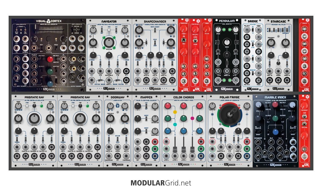
No issue that I can see. This is the correct patch.
Thanks for elaborating. A photo always works best!
I think possibly the perceived issue is this:
My impression from other posts and the Vidiot manual and so forth has been that this should sync correctly, you will just get monochrome Vidiot output because the VC composite decoder only extracts luma. It seems neither of us have been successful with such a connection, which presents some confusion in getting a working sync configuration.
When using Vidiot and Visual Cortex together, Visual Cortex should be the master sync generator.
Vidiot sync alternatives?
Hi everyone!
Well, i´m using vidiot and visual cortex. i use VC as a master and Vidiot as a slave. I can synchronize them without problem but i would like to know if there is a possibility to use the 1/8¨ video jack input (luma input jack) in the rear panel of vidiot to receive sync signal from VC.
Actually vidiot receive sync signal from VC through the video RCA input, and i would prefer to use this input for other things like feed a videocamera to do feedback.
is possible to use the luma input jack to sync ??
thank you!
Thread Replies
Vidiot can receive sync signal from Cortex by using any of Cortex’s 3 video outputs (2x CVBS Composite or Y/Luma).
Interference / distortion with either Visual Cortex or Memory Palace
I seem to be getting scrolling horizontal lines with my LZX setup, which just consists of the Visual Cortex and Memory Palace. I can’t tell where the interference is coming from— is it the component inputs on the Memory Palace, something happening with the sync between the two, etc?
I was hoping maybe someone here has seen this before and knows what the issue is.
Thread Replies
Likely culprit is power. What is your power supply?
TipTop Happy Ending rack.
1 x µzeus 4hp psu with 2 x flying bus boards
1 x 15v DC 1000ma Triad external power adapter (for 110v only)I’ve used uZeus before and it gives really unsatisfactory results for video synthesis, unfortunately. Their Studio Bus solution works pretty well.
Could you share a photo of your patch?
Hey y’all, just want you to know that I solved this problem!
The uZeus supports two ribbons, I had a second ribbon plugged into the uZeus with nothing else attached to said ribbon. I removed it, no more distortion.
Did I mention I’m new to the whole video synthesis thing? I’m new to the whole video synthesis thing.
Can I use the Andor 1 media player with Vidiot and other video synth modules?
Yes. Andor 1 can send Composite Video (NTSC & PAL) via a 3.5mm TRRS to A/V Cable (included with the deluxe version.) It may be used to input video to Visual Cortex, Vidiot, and Cadet III Video Input. Color input can be achieved with the upcoming Orion TBC2 module or with Visual Cortex and an external Composite-to-Component YPbPr video converter.
Connecting Liquid TV to Visual Cortex
Hello – I just took my first LZX plunge and ordered a VC and Liquid TV. Can someone confirm whether I need to connect them together via the RCA connections in the rear of the modules for sync purposes?
Jim
Thread Replies
you don’t have to but you can
if you don’t then you can plug one of the visual cortex RCA outputs into the liquid tv RCA input and then still patch signals into the 1,2,3, inputs
or if you have the RCA cables connected behind the front panels then you could just freely patch to the 1,2,3 inputs
for me it mostly depends on if I think I’ll be plugging other external non LZX system sources into the RCA jack on the front
The standard composite input will work without a sync cable. However, In order for the preview driver to function you would need a sync cable to go from both modules (Visual Cortex Sync Out to Liquid TV Sync In).
Hello,
So sorry, but I’m still not understanding this…I do appreciate your response, though! If I connect the RCA cable in the rear, what cable(s) do I use to connect the VC to the Liquid TV?
Thank you!
Jim
The Sync cables I use for my system are available to buy from the LZX website. These cables were designed specifically for Sync. I think you might be able to use standard yellow composite cables, but I’m not 100% sure.
I use standard composite cables with right-angle adaptors.
nothing special about the cables from LZX (although they are awesome!) you can use regular yellow composite cables.
keep the cables as short as possible for best practice 
Yeah, I had a slight feeling that you could use yellow composite cables for sync, but I referred the LZX cables to avoid giving any misleading info that I was unsure about
Have you checked the user reference card? It explains the connections and settings. Let me know if you’re unclear on anything.
I bought a Liquid TV from Perfect Circuit recently, and I’m having trouble getting the Preview function to work. The VID function works perfectly, and I’m able to monitor video on the composite input , but none of the Preview slots work when the switch on the top left is set to PVW and I’ve chosen one of the three slots
I’m syncing it to the Visual Cortex - see the screenshots. I’ve double checked, and swapped cables, but the Preview still eludes me. I tried the Reset in the Menu when in VID mode, but same thing.
I’ve tried patching all sorts of things into the Preview inputs - shapes and ramps from the VC, straight and through Color Chords, output from a Prismatic Ray, luma out from a Vidiot, but no dice.
When on one of the Preview slots, the screen will flash blue briefly with some text that I don’t have time to read - a microsecond and it’s gone.
Hopefully I’m missing something simple. Thoughts?


Looks like you have everything set correctly to me.
If you switch the sync src to “video in”, send the video in (via front) a video signal from cortex, do the preview inputs work now? In either case, best to arrange an RMA with us.
When I have the sync switch set to video in, and the composite from the Cortex going to the front of the Liquid TV, everything works, including the preview.
Is having the Liquid TV syncing in the back to the Cortex a problem when also having the Cortex coming into the front via composite for color monitoring?
Discuss on the Expedition series overview · Search forum for Visual Cortex · Search forum